Mucool Hydrogen Absorber R&D - BETACOOL home page
Mucool Hydrogen Absorber R&D - BETACOOL home page
Mucool Hydrogen Absorber R&D - BETACOOL home page

You also want an ePaper? Increase the reach of your titles
YUMPU automatically turns print PDFs into web optimized ePapers that Google loves.
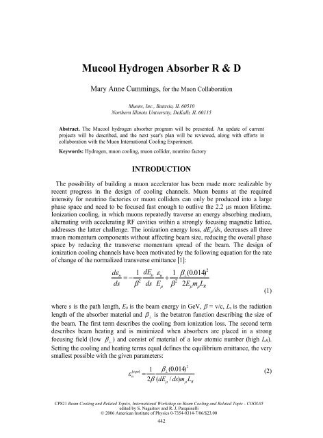
<strong>Mucool</strong> <strong>Hydrogen</strong> <strong>Absorber</strong> R & D<br />
Mary Anne Cummings, for the Muon Collaboration<br />
Muons, Inc., Batavia, IL 60510<br />
Northern Illinois University, DeKalb, IL 60115<br />
Abstract. The <strong>Mucool</strong> hydrogen absorber program will be presented. An update of current<br />
projects will be described, and the next year's plan will be reviewed, along with efforts in<br />
collaboration with the Muon International Cooling Experiment.<br />
Keywords: <strong>Hydrogen</strong>, muon cooling, muon collider, neutrino factory<br />
2<br />
dεn<br />
1 dEµ<br />
εn<br />
1 β⊥(<br />
0.<br />
014)<br />
= − +<br />
2<br />
2<br />
ds β ds E β 2E<br />
m L<br />
ε<br />
INTRODUCTION<br />
The possibility of building a muon accelerator has been made more realizable by<br />
recent progress in the design of cooling channels. Muon beams at the required<br />
intensity for neutrino factories or muon colliders can only be produced into a large<br />
phase space and need to be focused fast enough to outlive the 2.2 µs muon lifetime.<br />
Ionization cooling, in which muons repeatedly traverse an energy absorbing medium,<br />
alternating with accelerating RF cavities within a strongly focusing magnetic lattice,<br />
addresses the latter challenge. The ionization energy loss, dEµ/ds, decreases all three<br />
muon momentum components without affecting beam size, reducing the overall phase<br />
space by reducing the transverse momentum spread of the beam. The design of<br />
ionization cooling channels have been motivated by the following equation for the rate<br />
of change of the normalized transverse emittance [1]:<br />
=<br />
1<br />
µ<br />
( equ)<br />
⊥<br />
n<br />
2β<br />
( µ<br />
µ<br />
2<br />
β ( 0.<br />
014)<br />
dE / ds)<br />
mµ<br />
L<br />
R<br />
µ R<br />
where s is the path length, Eµ is the beam energy in GeV, β = v/c, LR is the radiation<br />
length of the absorber material and β ⊥ is the betatron function describing the size of<br />
the beam. The first term describes the cooling from ionization loss. The second term<br />
describes beam heating and is minimized when absorbers are placed in a strong<br />
focusing field (low β ⊥ ) and consist of material of a low atomic number (high LR).<br />
Setting the cooling and heating terms equal defines the equilibrium emittance, the very<br />
smallest possible with the given parameters:<br />
442<br />
(1)<br />
(2)
A figure of merit can be defined as [LRdEµ/ds)] 2 , the square coming from the two<br />
transverse directions. Figure 1 shows this number for several materials, with<br />
hydrogen, in its liquid or gaseous state, being optimal for the lowest achievable<br />
emittance.<br />
TABLE 1. Cooling figures of merit for various light materials relative to liquid hydrogen.<br />
Material (MeV g -1 cm 2 ) LR (g cm -2 ) Merit<br />
GH2 4.103 61.28 1.03<br />
LH2 4.034 61.28 1<br />
He 1.937 94.32 0.55<br />
LiH 1.94 86.9 0.47<br />
Li 1.639 82.76 0.30<br />
GH4 2.417 46.22 0.20<br />
Be 1.594 65.19 0.18<br />
THE MUCOOL COLLABORATION<br />
The MuCool Collaboration consists of 18 institutions from the U.S.,Europe and<br />
Japan. The mission is 1) to design and prototype cooling channel components; 2)<br />
perform a high-power beam test of a cooling cell; and 3) work with the Muon<br />
International Cooling Experiment (MICE), particularly with the design and building of<br />
cooling channel elements.<br />
FIGURE 1. Cooling channel from Neutrino Factory . FIGURE 2. Plan view of a complete cooling cell test at<br />
the Study II. MTA.<br />
The MuCool R&D efforts have been based on the SFOFO cooling lattice described<br />
in the Neutrino Factory Study II [2]. This lattice includes 201 MHz RF cavities<br />
{Figure 1). The MICE cooling channel is based on this design, and one goal of the<br />
MuCool program is to construct and test elements from this channel together in a high<br />
intensity proton beam in the newly completed MuCool Test Area (MTA).<br />
Additionally, an FNAL study group was formed to design the beamline that will be<br />
located in the old Linac access tunnel and brought into the MTA for a proposed highpower<br />
test of a complete cooling cell (Figure 2). The beamline has been designed,<br />
costed and approved, and a safety analysis and shielding assessment has been<br />
completed for the MTA. Beam is scheduled for sometime in 2006.<br />
443
THE MUCOOL TEST AREA AT FNAL<br />
In late 2003, construction of the MTA was completed at the site of the old access<br />
tunnel to the FNAL Linac, and is now the focus of MuCool activity at FNAL. The<br />
MTA is designed to accommodate the full Linac intensity of 1.6X10 13 protons/pulse at<br />
15Hz or 2.4X10 14 protons/s, or 600W energy deposition into a 35 cm long liquid<br />
hydrogen absorber at 400 MeV. The test area will provide power from the Linac to<br />
operate 201 MHz and 805 MHz RF test cavities. A first LH2 test has been completed<br />
with the KEK convection absorber, and RF testing (both 805 and 201 MHz) is<br />
planned. A cryogenic facility is scheduled for completion near the end of 2005 that<br />
will provide refrigeration power of up to 350W for the hydrogen absorber, as well as<br />
cooling for the superconducting solenoid.<br />
LH2 ABSORBERS<br />
The issues that drive the absorber design and tests are: 1) the large amount of heat<br />
that needs to be extracted from high intensity beams; 2) the desire to minimize<br />
multiple scattering; and 3) the densely-packed and high radiation environment in<br />
which absorbers will be operating in a real cooling channel. Additionally, the<br />
combustive nature of hydrogen requires special safety considerations that drive much<br />
of the engineering and design.<br />
Minimizing the multiple scattering has lead to novel window designs that depart<br />
from the standard shell profiles [3]. For efficient heat removal, two different absorber<br />
designs have been proposed: 1) an internal heat exchange design, where the LH2<br />
mixing is achieved by natural convection cells, driven by the beam-deposited heat and<br />
the cold walls of the heat exchanger (with cold He gas) and 2) an external heat<br />
exchange design where the heat exchanger is in an external loop of hydrogen and the<br />
LH2 mixing is achieved with an external pump with nozzles oriented at various angles<br />
to establish turbulent flow. These are shown in Figure 4.<br />
Thin Window Designs and Test<br />
Designs for thin windows have matured, where windows of equivalent strength to<br />
standard designs have been realized with less than 30% their minimum thickness.<br />
Figure 3 shows the evolution of the window profiles. The current design has a profile<br />
with an inflected curvature where the thinnest section (around the center) is<br />
membrane-stress dominant: under the ultimate pressure (rupture) the greatest stress is<br />
experienced at the center.<br />
444
FIGURE 3. Evolution of thin window profiles. From left to right: standard torispherical shell with tapered ends to<br />
a normal surface, tapered torispherical to flange, inflected to flange, and thinned inflected.<br />
Earlier burst tests on thin membrane-stress dominated windowed did not produce<br />
shards, and demonstrated a window strength that was consistent with predictions from<br />
finite element analysis (FEA) predictions. To test the window performance,<br />
photogrammetry was used as a non-contact, large sampling method of measuring<br />
window profile deformation under pressure. This technique uses points of light<br />
projected onto the window surface, whose space locations were determined by a<br />
camera programmed to make parallax calculations [4]. The system has been upgraded<br />
to include a new projector lens and new camera software. Additionally, new methods<br />
of optical coating, including vapor deposition, are under consideration, as the thinness<br />
of the windows makes the variations in the thickness of the TiO optical coating<br />
manually applied a potential source of error. A set of safety requirements for the<br />
window design have been established for the MICE and MuCool experiments, and the<br />
MuCool window approach has passed the initial MICE safety review. A certification<br />
procedure for windows used in the cooling cells is being developed.<br />
<strong>Absorber</strong> Manifold Design<br />
The program for the absorber manifolds is proceeding in parallel paths. The<br />
external heat exchange, or forced-flow prototype has been built, and is currently set up<br />
in Lab P8 at FNAL for room temperature flow tests using an infrared camera. A<br />
design for an absorber manifold, cryostat and external hydrogen loop with pump and<br />
heat exchange is near completion and will be the first absorber tested in a beam at the<br />
MTA (Figure 4, right). The cryostat is designed to slide into the solenoid from Lab G,<br />
with the absorber in the magnets center. This is the absorber planned for the first<br />
complete cooling cell test.<br />
A prototype convection absorber design has been manufactured and tested by the<br />
KEK/Osaka group (Figure 4, left) [5]. This prototype was delivered to the MTA late in<br />
2003. The absorber is cooled by cold helium gas (~15K) from dewars, circulated<br />
behind the wall of the absorber interior. Heating coils are installed at the absorber<br />
bottom and center using warm helium gas. In August 2004, after a lengthy safety<br />
review, the absorber was completely filled with liquid hydrogen, at a temperature of<br />
18K maintained stably over a period of several hours. Several operational issues were<br />
successfully resolved and the safety and controls system refined with this first run.<br />
Initial heat loading tests indicated that heat absorption of 20W or more can be<br />
accomplished at a stable temperature. Plans for the next test in will include upgrades<br />
to the absorber instrumentation: new, better resolution temperature probes, a level<br />
445
sensor, and temperature probes placed inside the input and output cold helium for<br />
better determination of cooling efficiency.<br />
FIGURE 4. Two LH 2 absorber prototypes, convection type, internal heat exchange (left) and forced-flow, external<br />
heat exchange (right). The far right picture shows the forced-flow absorber inside of a solenoid for the MTA tests.<br />
Results from both the KEK tests and the room temperature flow tests will be<br />
compared with flow simulations of both prototype designs to predict performance in a<br />
real beam.<br />
HIGH-PRESSURE RF CAVITIES<br />
A novel approach to ionization cooling is being developed that uses high-pressure<br />
hydrogen gas at liquid nitrogen temperatures, with a density 0.5 that of liquid<br />
hydrogen. This idea of filling RF cavities with gas is new for particle accelerators, and<br />
is only possible for muons since they neither scatter as do strongly interacting<br />
protons, nor shower as do less-massive electrons. Instead of discrete absorbers, the<br />
gaseous hydrogen would fill the accelerating RF cavities. Dark currents are suppressed<br />
due to Paschen’s Law, a property first observed in 19th century when sparking in<br />
vacuum tubes was suppressed when the tubes where filled with a pressurized inert gas.<br />
Consequently, a much higher gradient is possible in a hydrogen-filled RF cavity than<br />
is needed to overcome the ionization energy loss, provided one can supply the<br />
required RF power. <strong>Hydrogen</strong> is also twice as effective as helium in ionization cooling<br />
effectiveness, viscosity, and heat capacity.<br />
Measurements by Muons, Inc. and IIT at FNAL have demonstrated that hydrogen<br />
gas suppresses RF breakdown very well, about a factor six better than helium at the<br />
same temperature and pressure [6]. A small RF cavity test cell was built and run at<br />
446
FNAL’s Lab G using power from the Lab G klystron. The cell was run up to 80<br />
MV/m after conditioning and before breakdown with a H2 gas pressure of 31 atm at<br />
80K. The next tests will be conducted at the MTA at FNAL. Current R & D plans<br />
include tests of pressurized RF cavities in magnetic fields and high radiation<br />
environments, and the use of new cavity construction materials, including beryllium<br />
RF windows for improved cavity performance. A beam test is scheduled for 2006 in<br />
the MTA.<br />
SUMMARY<br />
The MuCool collaboration has successfully resolved many outstanding technical and<br />
safety issues surrounding the use of hydrogen. The MTA is complete, on budget and<br />
on schedule. A major milestone was accomplished with the first absorber test with<br />
liquid hydrogen. The work involved in achieving safe, stable operation of the KEK<br />
convection type absorber builds a foundation for all subsequent reviews of absorber<br />
operation, including a high-powered run with a complete cooling cell. This test has<br />
also pushed the development of absorber instrumentation, and the work on safe<br />
operation at FNAL has expedited the successful completion of the first MICE safety<br />
review. The thin window design and testing have matured, and the window design has<br />
been adapted for the 201 MHz RF cell. An operational beamline is on schedule to run<br />
as early as 2006 in the MTA for tests on LH2 and GH2 absorber prototypes.<br />
REFERENCES<br />
1. D. Neuffer, µ + -µ - Collider, CERN 99-12 (1999).<br />
2. M. Zisman and J. Gallardo, eds., "Feasibility Study-II of a Muon-based Neutrino Source" BNL-52623, June<br />
(2001). http://www.cap.bnl.gov/mumu/studyii/FS2-report.htm<br />
3. M. A. C. Cummings et al, “The MuCool/MICE LH2 <strong>Absorber</strong> Program", Nufact03 Conference Proceedings,<br />
(2003).<br />
4. E. M. Mikhail, J. S. Bethel, and J. C. McGlone, Introduction to Modern Photogrammetry, New York, John Wiley<br />
& Sons, Inc. (2001).<br />
5. M. A. C. Cummings and S. Ishimoto, “Progress on the Liquid <strong>Hydrogen</strong> <strong>Absorber</strong> for the MICE Cooling<br />
Channel”, PAC 2005, paper WPAE022, (2005).<br />
6. R. Johnson et al, “High Pressure, High gradient RF Cavities for Muon Beam Cooling”, LINAC2004,<br />
Lubeck, Germany (2004).<br />
447