Intel® Desktop Board D875PBZ Quick Reference
Intel® Desktop Board D875PBZ Quick Reference
Intel® Desktop Board D875PBZ Quick Reference

You also want an ePaper? Increase the reach of your titles
YUMPU automatically turns print PDFs into web optimized ePapers that Google loves.
Intel ® <strong>Desktop</strong> <strong>Board</strong> <strong>D875PBZ</strong><br />
<strong>Quick</strong> <strong>Reference</strong><br />
This guide is written for technically qualified personnel with experience<br />
installing and configuring desktop boards.<br />
Before You Begin ................................................................................ 3<br />
<strong>Desktop</strong> <strong>Board</strong> Components ........................................................ 4<br />
Supported Components<br />
Processors ............................................................................................ 6<br />
Memory Module Requirements........................................................... 6<br />
Installation Steps<br />
1. Installing the I/O Shield ............................................................. 8<br />
2. Installing the <strong>Desktop</strong> <strong>Board</strong>...................................................... 8<br />
3. Installing the Processor .............................................................. 9<br />
4. Installing Memory Modules....................................................... 9<br />
5. Installing an AGP Card ............................................................ 10<br />
6. Attaching IDE Drives............................................................... 12<br />
7. Attaching Serial ATA (SATA) Drives .................................... 13<br />
8. Configuring the System for Intel ® RAID Technology<br />
for Serial ATA.......................................................................... 14<br />
9. Connecting Internal Headers.................................................... 17<br />
10. Connecting Hardware Control ................................................. 18<br />
11. Connecting Power Cables ........................................................ 18<br />
Using the BIOS Setup Program ................................................ 19<br />
Setting the BIOS Configuration Jumper Block................ 19<br />
Troubleshooting................................................................................. 20<br />
Customer Support Links............................................................... 21<br />
Items on the Intel ® Express Installer CD-ROM<br />
• Product warranty<br />
• Intel Express Installer<br />
• Intel ® <strong>Desktop</strong> <strong>Board</strong> <strong>D875PBZ</strong> Product Guide<br />
• Software utilities and drivers<br />
• Software license agreement<br />
• Readme file<br />
Part Number: C24495-003<br />
C24495-003
INFORMATION IN THIS DOCUMENT IS PROVIDED IN CONNECTION WITH<br />
INTEL ® PRODUCTS. NO LICENSE, EXPRESS OR IMPLIED, BY ESTOPPEL OR<br />
OTHERWISE, TO ANY INTELLECTUAL PROPERTY RIGHTS IS GRANTED BY<br />
THIS DOCUMENT. EXCEPT AS PROVIDED IN INTEL’S TERMS AND<br />
CONDITIONS OF SALE FOR SUCH PRODUCTS, INTEL ASSUMES NO<br />
LIABILITY WHATSOEVER, AND INTEL DISCLAIMS ANY EXPRESS OR<br />
IMPLIED WARRANTY, RELATING TO SALE AND/OR USE OF INTEL<br />
PRODUCTS INCLUDING LIABILITY OR WARRANTIES RELATING TO FITNESS<br />
FOR A PARTICULAR PURPOSE, MERCHANTABILITY, OR INFRINGEMENT OF<br />
ANY PATENT, COPYRIGHT OR OTHER INTELLECTUAL PROPERTY RIGHT.<br />
INTEL PRODUCTS ARE NOT INTENDED FOR USE IN MEDICAL, LIFE<br />
SAVING, OR LIFE SUSTAINING APPLICATIONS. INTEL MAY MAKE<br />
CHANGES TO SPECIFICATIONS AND PRODUCT DESCRIPTIONS AT ANY<br />
TIME, WITHOUT NOTICE.<br />
Intel ® <strong>Desktop</strong> <strong>Board</strong> <strong>D875PBZ</strong> may contain design defects or errors known as<br />
errata which may cause the product to deviate from published specifications.<br />
Current characterized errata are available on request.<br />
Contact your local Intel sales office or your distributor to obtain the latest<br />
specifications and before placing your product order.<br />
Copies of documents which have an ordering number and are referenced in this<br />
document, or other Intel literature, may be obtained from Intel Corporation by<br />
going to the World Wide Web site at: http://www.intel.com or by calling<br />
1-800-548-4725.<br />
Intel and Pentium are registered trademarks of Intel Corporation or its subsidiaries<br />
in the United States and other countries.<br />
* Other names and brands may be claimed as the property of others.<br />
Copyright © 2003, Intel Corporation<br />
2 Intel <strong>Desktop</strong> <strong>Board</strong> <strong>D875PBZ</strong> <strong>Quick</strong> <strong>Reference</strong>
Before You Begin<br />
Warning and Cautions<br />
WARNING<br />
Disconnect the desktop board's power supply from its AC power<br />
source before you connect or disconnect cables, or install or remove<br />
any board components. Failure to do this can result in personal<br />
injury or equipment damage. Some circuitry on the desktop board<br />
can continue to operate even though the front panel power switch is<br />
off.<br />
CAUTION<br />
Electrostatic discharge (ESD) can damage desktop board components.<br />
Install the board at an ESD-controlled workstation. If such a workstation is<br />
not available, wear an antistatic wrist strap or touch the surface of the<br />
antistatic package before handling the board.<br />
CAUTION<br />
Many of the midboard and front panel connectors provide operating<br />
voltage (+5 V DC and +12 V DC, for example) to devices inside the<br />
computer chassis, such as fans and internal peripherals. These<br />
connectors are not overcurrent protected. Do not use these connectors for<br />
powering devices external to the computer chassis. A fault in the load<br />
presented by the external devices could cause damage to the computer,<br />
the interconnecting cables, and the external devices themselves.<br />
Safety and Regulatory Notice<br />
See the Intel ® <strong>Desktop</strong> <strong>Board</strong> <strong>D875PBZ</strong> Product Guide for all applicable<br />
regulatory compliance statements, product certification markings, and safety and<br />
electromagnetic compatibility (EMC) standards and regulations the desktop<br />
board is compliant with.<br />
Replacement battery warning label provided: Place the label inside the chassis<br />
in an easy-to-see location near the battery but not on the board itself.<br />
Intended uses: This product was evaluated as information technology<br />
equipment (ITE) for home or office use when installed into an appropriate<br />
computer chassis. Other end uses or locations may require further evaluation.<br />
Intel <strong>Desktop</strong> <strong>Board</strong> <strong>D875PBZ</strong> <strong>Quick</strong> <strong>Reference</strong> 3
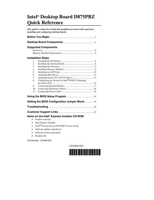
<strong>Desktop</strong> <strong>Board</strong> Components<br />
W<br />
V<br />
U<br />
T<br />
S<br />
3<br />
1<br />
Power LED<br />
R<br />
P<br />
Q<br />
On/Off<br />
N<br />
O<br />
Power LED<br />
USB 2.0<br />
Devices<br />
A<br />
B<br />
M<br />
USB 2.0<br />
Devices<br />
RJ45<br />
OM15666<br />
4 Intel <strong>Desktop</strong> <strong>Board</strong> <strong>D875PBZ</strong> <strong>Quick</strong> <strong>Reference</strong><br />
L<br />
No Connection<br />
Reset<br />
HD LED<br />
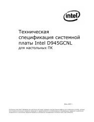
Figure 1. <strong>Desktop</strong> <strong>Board</strong> Components<br />
K<br />
J<br />
C<br />
D<br />
E<br />
F<br />
G<br />
H<br />
I<br />
continued
<strong>Desktop</strong> <strong>Board</strong> Components (continued)<br />
Label Description<br />
A AGP connector<br />
B Rear chassis fan header (fan speed control)<br />
C 12 V processor core voltage connector<br />
D VREG fan header<br />
E Processor socket<br />
F Processor fan header<br />
G Intel ® 82875P (MCH)<br />
H Channel A DIMM sockets<br />
I Channel B DIMM sockets<br />
J Main power connector<br />
K Diskette drive connector<br />
L Primary IDE connector<br />
M Secondary IDE connector<br />
N SCSI hard drive activity LED header<br />
O Front chassis fan header (fan speed control)<br />
P Serial ATA connectors<br />
Q BIOS configuration jumper<br />
R Speaker<br />
S USB 2.0 header<br />
T Chassis intrusion header<br />
U Battery<br />
V Intel ® 82801ER (ICH5)<br />
W PCI bus add-in card connectors<br />
Intel <strong>Desktop</strong> <strong>Board</strong> <strong>D875PBZ</strong> <strong>Quick</strong> <strong>Reference</strong> 5
Supported Components<br />
Processors<br />
The board supports a single processor with the following features:<br />
Type<br />
Intel ® Pentium ® 4<br />
processor supporting<br />
Hyper-Threading<br />
Technology<br />
Designation<br />
3.0, 2.80C, 2.60C, and<br />
2.40C GHz<br />
Intel Pentium 4 processor 2.8, 2.66, 2.53, 2.4B,<br />
and 2.26 GHz<br />
1 Front side bus<br />
FSB 1<br />
Frequency<br />
L2 Cache<br />
800 MHz 512 KB<br />
3.06 GHz 533 MHz 512 KB<br />
533 MHz 512 KB<br />
For the latest information on processors supported by <strong>Desktop</strong> <strong>Board</strong> <strong>D875PBZ</strong>,<br />
refer to the Intel World Wide Web site at:<br />
http://support.intel.com/support/motherboards/desktop<br />
Memory Module Requirements<br />
The desktop board supports system memory as defined below:<br />
Memory<br />
Front Side Bus Memory Speed<br />
Speed Processor<br />
Frequency Outcome<br />
DDR400 Intel Pentium 4 processor 800 MHz 400 MHz<br />
DDR333 Intel Pentium 4 processor 800 MHz 320 MHz<br />
Intel Pentium 4 processor 533 MHz 333 MHz<br />
• Up to four 184-pin Double Data Rate (DDR) SDRAM Dual Inline Memory<br />
Module (DIMM) connectors with gold-plated contacts.<br />
• Support for:<br />
⎯ Unbuffered, non-registered single or double-sided DIMMs<br />
⎯ Serial Presence Detect (SPD) memory only<br />
⎯ Support for Suspend to RAM (STR), S3 ACPI state<br />
⎯ ECC or non-ECC RAM memory<br />
⎯ 2.5 V memory<br />
NOTE<br />
ECC memory support must be enabled in BIOS.<br />
6 Intel <strong>Desktop</strong> <strong>Board</strong> <strong>D875PBZ</strong> <strong>Quick</strong> <strong>Reference</strong>
NOTES<br />
System resources (such as PCI and AGP) require physical memory<br />
address locations that reduce available memory addresses above 3 GB.<br />
This may result in less than 4 GB of memory being available to the<br />
operating system and applications.<br />
All memory components and DIMMs used with the desktop board must<br />
comply with the PC SDRAM specifications. These include the PC SDRAM<br />
Specification (memory component specific), the PC Unbuffered DIMM<br />
Specification. To view or download these specifications, refer to this Intel<br />
World Wide Web site at:<br />
http://developer.intel.com/technology/memory/pcsdram/spec/<br />
For information about vendors that support these memory requirements,<br />
refer to the <strong>Desktop</strong> <strong>Board</strong> <strong>D875PBZ</strong> link on this Intel World Wide Web<br />
site at:<br />
http://support.intel.com/support/motherboards/desktop/<br />
Intel <strong>Desktop</strong> <strong>Board</strong> <strong>D875PBZ</strong> <strong>Quick</strong> <strong>Reference</strong> 7
Installation Steps<br />
1. Installing the I/O Shield<br />
The board comes with an I/O shield that is used to block radio frequency<br />
transmissions, necessary to pass emissions (EMI) certification testing, protect<br />
internal components from dust and foreign objects, and promote correct airflow<br />
within the chassis.<br />
Install the I/O shield before installing the board in the chassis. Place the shield<br />
inside the chassis as shown in Figure 2. Press the shield into place so that it fits<br />
tightly and securely. If the shield doesn’t fit, obtain a properly sized shield from<br />
the chassis supplier.<br />
Figure 2. I/O Shield<br />
OM15474<br />
2. Installing the <strong>Desktop</strong> <strong>Board</strong><br />
Refer to your chassis manual for specific instructions on installing and removing<br />
the desktop board.<br />
Secure <strong>Desktop</strong> <strong>Board</strong> <strong>D875PBZ</strong> to the chassis using the 10 screws. Refer to<br />
Figure 1 on page 4 for the location of the screw mounting holes.<br />
8 Intel <strong>Desktop</strong> <strong>Board</strong> <strong>D875PBZ</strong> <strong>Quick</strong> <strong>Reference</strong>
3. Installing the Processor<br />
To install the processor, follow these steps (see Figure 3):<br />
1. Observe the precautions in “Before You Begin” on page 3.<br />
2. Lift the processor socket lever.<br />
3. Install the processor so that the corner with the triangle marking (A) is<br />
aligned with the corner where the lever is attached to the socket.<br />
4. Lower the lever back to its original position.<br />
mPGA478B<br />
mPGA478B<br />
Figure 3. Installing a Processor<br />
mPGA478B<br />
OM12078<br />
5. The desktop board has an integrated processor fan heat sink retention<br />
mechanism (RM). For instructions on how to install the processor fan heat<br />
sink, refer to the boxed processor manual or the Intel World Wide Web<br />
site at:<br />
http://support.intel.com/support/processors/pentium4/intnotes478.htm<br />
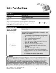
4. Installing Memory Modules<br />
CAUTION<br />
Install memory in the DIMM sockets prior to installing the AGP video card<br />
to avoid interference with the memory retention mechanism.<br />
<strong>Desktop</strong> <strong>Board</strong> <strong>D875PBZ</strong>’s four DIMM sockets are arranged as DIMM 0 and<br />
DIMM 1 in both Channel A and Channel B, as shown in Figure 4.<br />
Dual Channel Configuration<br />
Install a matched pair of DIMMs (equal in speed: DDR266, DDR333, or<br />
DDR400; density: 64 MB, 128 MB, 256 MB, 512 MB, or 1 GB; and<br />
technology: 128 Mb, 256 Mb, or 512 Mb) in DIMM 0 in both Channels A and<br />
B. If additional memory is to be used, then install another matched pair of<br />
DIMMs in DIMM 1 in both Channels A and B.<br />
NOTE<br />
All other memory configurations will result in single channel memory<br />
operation.<br />
Intel <strong>Desktop</strong> <strong>Board</strong> <strong>D875PBZ</strong> <strong>Quick</strong> <strong>Reference</strong> 9<br />
A
To install DIMMs, follow these steps (see Figure 4):<br />
1. Observe the precautions in “Before You Begin” on page 3.<br />
2. Remove the AGP video card if it interferes with the DIMM clips from<br />
being easily opened and closed.<br />
3. Align the small notch at the bottom edge of the DIMM with the key in the<br />
socket.<br />
4. Insert the bottom edge of the DIMM into the socket.<br />
5. Push down on the top edge of the DIMM until the retaining clips snap into<br />
place. Make sure the clips are firmly in place.<br />
5. Installing an AGP Card<br />
Figure 4. Installing DIMMs<br />
Channel A<br />
DIMM 0<br />
DIMM 1<br />
Channel B<br />
DIMM 0<br />
DIMM 1<br />
OM15667<br />
CAUTION<br />
Care must be taken when installing an AGP card into an AGP connector.<br />
When installing any AGP card in the desktop board, ensure that it is fully<br />
seated in the AGP connector before you power on the system. If the card<br />
is not fully seated in the AGP connector, an electrical short may result<br />
across the AGP connector pins. Depending on the over-current protection<br />
of the power supply, certain board components and/or traces may be<br />
damaged.<br />
NOTE<br />
<strong>Desktop</strong> <strong>Board</strong> <strong>D875PBZ</strong> is only compatible with 1.5 V or 0.8 V AGP<br />
cards. Do not attempt to install a legacy 3.3 V AGP card. The AGP<br />
connector is not mechanically compatible with legacy 3.3 V AGP cards.<br />
10 Intel <strong>Desktop</strong> <strong>Board</strong> <strong>D875PBZ</strong> <strong>Quick</strong> <strong>Reference</strong>
<strong>Desktop</strong> <strong>Board</strong> <strong>D875PBZ</strong> has an integrated AGP card retention mechanism<br />
(RM). Follow these instructions to install an AGP card (see Figure 5):<br />
1. Observe the precautions in “Before You Begin” on page 3.<br />
2. Place the AGP card in the AGP connector.<br />
3. Press down on the card until it is completely seated in the connector and the<br />
card retention notch snaps into place below the RM.<br />
4. Secure the card’s metal bracket to the chassis back panel with a screw.<br />
Install PCI cards into the PCI bus add-in card connectors on the desktop board.<br />
Figure 5. Installing an AGP Card<br />
OM14695<br />
To remove the AGP card, reverse steps taken when installing an AGP card.<br />
Before removing the card, make sure to push back on the RM lever (A) until the<br />
retention pin completely clears the notch in the card.<br />
Intel <strong>Desktop</strong> <strong>Board</strong> <strong>D875PBZ</strong> <strong>Quick</strong> <strong>Reference</strong> 11<br />
A
6. Attaching IDE Drives<br />
The Intel ® boxed desktop board package includes an ATA-66/100 cable.<br />
The cable supports the ATA-66/100 (40-contact, 80-conductor) transfer protocol<br />
and is backward compatible with drives using slower IDE transfer protocols.<br />
The cable can connect two drives to the desktop board.<br />
The cable will work correctly only when oriented as in Figure 6. For correct<br />
cable function:<br />
1. Observe the precautions in “Before You Begin” on page 3.<br />
2. Attach the cable end with the single connector (A) to the board.<br />
3. Attach the cable end with the two closely spaced connectors (B) to the<br />
drives.<br />
A<br />
Figure 6. Connecting the IDE Cable<br />
OM15669<br />
12 Intel <strong>Desktop</strong> <strong>Board</strong> <strong>D875PBZ</strong> <strong>Quick</strong> <strong>Reference</strong><br />
B
7. Attaching Serial ATA (SATA) Drives<br />
The boxed desktop board package includes two Serial ATA (SATA) cables.<br />
The cable (4-conductor) supports the Serial ATA protocol and connects a single<br />
drive to the desktop board. Either end of the cable can be connected to the<br />
SATA drive or the connector on the board.<br />
For correct cable function (see Figure 7):<br />
1. Observe the precautions in “Before You Begin” on page 3.<br />
2. Attach either cable end to the connector (A) on the board.<br />
3. Attach the other cable end (B) to the drive.<br />
A<br />
NOTE<br />
Figure 7. Connecting the SATA Cable<br />
OM15670<br />
The Serial ATA boot option is disabled by default in the BIOS Setup<br />
program. To boot from an SATA drive, the Serial ATA boot option must<br />
be enabled in the BIOS.<br />
NOTE<br />
Some Serial ATA drives may require a power adapter cable. Contact the<br />
manufacturer of the SATA drive to determine the best method for powering<br />
the SATA drive.<br />
Intel <strong>Desktop</strong> <strong>Board</strong> <strong>D875PBZ</strong> <strong>Quick</strong> <strong>Reference</strong> 13<br />
B
8. Configuring the System for Intel ® RAID<br />
Technology for Serial ATA<br />
NOTE<br />
Intel ® RAID Technology for Serial ATA is supported with Microsoft<br />
Windows* XP only.<br />
Configuring the BIOS for Intel RAID Technology for Serial ATA<br />
The RAID option must be enabled in BIOS before the system can load the<br />
option ROM code for Intel RAID.<br />
1. Enter the BIOS Setup program by pressing the key after the Power-<br />
On-Self-Test (POST) memory test begins.<br />
2. Select the Advanced menu and then the Drive Configuration menu.<br />
3. Switch the ATA/IDE Configuration option from Legacy to Enhanced.<br />
Next, switch the RAID option to Enabled.<br />
4. Press to save the BIOS settings and exit the BIOS Setup program.<br />
Creating, Deleting, and Resetting RAID Sets<br />
The Serial ATA RAID set must be administered in the RAID Configuration<br />
utility. During POST, the following message will appear for a few seconds:<br />
Press to enter Raid Configuration utility<br />
After the above message appears, press the and keys simultaneously.<br />
Create RAID 0 Volume<br />
1. Select option 1 Create RAID Volume and press the key.<br />
2. Select the stripe value for the RAID 0 array by scrolling through the<br />
available values by using the or keys and pressing the <br />
key.<br />
3. The available values range from 8 KB to 128 KB in 8 KB increments. The<br />
stripe value should be chosen based on the planned drive usage. Some<br />
suggested selections are listed below. The default selection is 64 KB.<br />
• 16 KB – low disk usage<br />
• 64 KB – typical disk usage<br />
• 128 KB – performance disk usage<br />
4. Press the key again to the Create Volume prompt to create the<br />
array. Confirm this selection by pressing the key after the prompt.<br />
5. Scroll to option 4 Exit and press the key to exit the RAID<br />
Configuration utility. Confirm the exit by pressing key.<br />
14 Intel <strong>Desktop</strong> <strong>Board</strong> <strong>D875PBZ</strong> <strong>Quick</strong> <strong>Reference</strong>
Delete RAID Volume<br />
CAUTION<br />
All data on the RAID drives will be lost.<br />
1. Select option 2 Delete RAID Volume and press the key to<br />
delete the RAID set.<br />
2. Press the key to delete the RAID volume. Confirm the<br />
volume deletion by pressing the key.<br />
Reset RAID Data<br />
CAUTION<br />
All data on the RAID drives and any RAID structures will be lost.<br />
1. Select option 3 Reset RAID Data and press the key to delete<br />
the RAID set and remove any RAID structures from the drives.<br />
2. Confirm the selection by pressing the key.<br />
Loading the Intel ® Application Accelerator 3.0 RAID Edition Driver<br />
For Microsoft Windows XP, follow these steps to install the RAID driver:<br />
1. As Windows Setup begins, press to specify the RAID driver.<br />
2. When queried by the installation screen, press to specify an additional<br />
device.<br />
3. Insert the floppy disk labeled Intel ® Application Accelerator 3.0 RAID<br />
Edition Driver and press .<br />
4. Press to select the Intel RAID controller.<br />
5. Press to continue with Windows Setup.<br />
Configuring an Intel RAID Ready System<br />
The Intel Application Accelerator 3.0 RAID Edition software offers the<br />
flexibility to upgrade from a single Serial ATA drive to a two drive RAID 0<br />
configuration when an additional Serial ATA drive is added to the system.<br />
However, several important steps must be followed at the time the system is first<br />
configured in order to take advantage of RAID when upgrading to a second<br />
Serial ATA drive.<br />
1. The BIOS must be configured for RAID before installing Windows XP on<br />
the single Serial ATA drive. Refer to section ‘Configuring the BIOS for<br />
Intel RAID Technology for Serial ATA’ on page 14 to properly configure<br />
the BIOS.<br />
2. Install the Intel RAID driver during Window Setup. Refer to section<br />
“Loading the Intel Application Accelerator 3.0 RAID Edition Driver” to<br />
install the driver during Windows Setup.<br />
Intel <strong>Desktop</strong> <strong>Board</strong> <strong>D875PBZ</strong> <strong>Quick</strong> <strong>Reference</strong> 15
3. Install the operating system and then the Intel Application Accelerator 3.0<br />
RAID Edition software. The Intel Application Accelerator 3.0 RAID<br />
Edition software is included on the Intel ® Express Installer CD that ships<br />
with the desktop board.<br />
Upgrading to Serial ATA RAID 0 Configuration from a Single Drive<br />
Configuration<br />
1. Install the second Serial ATA drive in the system. Refer to section<br />
“Attaching Serial ATA (SATA) Drives” on page 13.<br />
2. Start the system and boot into Windows XP.<br />
3. Launch the Intel Application Accelerator from the Start Menu<br />
(Start All Programs Intel Application Accelerator RAID Edition <br />
Intel Application Accelerator).<br />
4. From the Integrated RAID tab, right-click on “RAID Volume” and select<br />
“Create from Existing Disk.”<br />
NOTE<br />
The RAID volume name must be in English alphanumeric ASCII<br />
characters and no more than 16 characters.<br />
5. Select the source disk to create the RAID Volume and then press the<br />
“Next” button.<br />
6. Enter the name of the RAID volume (default is RAID_Volume1).<br />
7. Select the stripe value for the RAID 0 array. The available values range<br />
from 8 KB to 128 KB in 8 KB increments. The stripe value should be<br />
chosen based on the planned drive usage. Some suggested selections are<br />
listed below. The default selection is 64 KB.<br />
• 16 KB – low disk usage<br />
• 64 KB – typical disk usage<br />
• 128 KB – performance disk usage<br />
8. Press the “Next” button to continue.<br />
9. Confirm creation of the RAID volume by pressing the “Yes” button.<br />
10. Reconfirm creation of the RAID volume by pressing the “Yes” button.<br />
11. Press the “Migrate” button to begin the data migration.<br />
NOTE<br />
Data migration will take a considerable amount of time. Do not power<br />
down or reset the system during migration.<br />
12. Reboot the system after migration completes by selecting “Yes” when<br />
prompted to do so.<br />
16 Intel <strong>Desktop</strong> <strong>Board</strong> <strong>D875PBZ</strong> <strong>Quick</strong> <strong>Reference</strong>
NOTE<br />
If an IDE hard drive is also attached to the system, the RAID volume will<br />
need to be moved up in priority in order to boot from it. After the system<br />
reboots, press the key to enter BIOS Setup. Then, navigate to the<br />
BOOT menu and select the Hard Disk Drives option. Move the RAID<br />
volume to the 1 st Drive position. Press to save the BIOS settings<br />
and exit the BIOS Setup program.<br />
9. Connecting Internal Headers<br />
Figure 8 shows the location of internal headers.<br />
USB B<br />
A<br />
Not Connected<br />
10 Key (no pin)<br />
Ground 8 7 Ground<br />
D+ 6 5 D+<br />
D- 4 3 D-<br />
Power (+5 V) 2 1<br />
Power (+5 V)<br />
J8J1<br />
USB A<br />
3<br />
B 1<br />
J9J1<br />
Item Description<br />
A USB 2.0<br />
B Power LED<br />
C Front panel<br />
9 N/C<br />
On/Off<br />
8<br />
6<br />
7<br />
5<br />
6<br />
Reset<br />
Power LED<br />
4<br />
2<br />
3<br />
1<br />
HD LED<br />
Figure 8. Location of Internal Headers<br />
OM15697<br />
Intel <strong>Desktop</strong> <strong>Board</strong> <strong>D875PBZ</strong> <strong>Quick</strong> <strong>Reference</strong> 17<br />
J8J2<br />
C
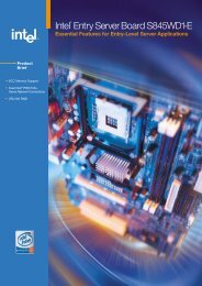
10. Connecting Hardware Control<br />
Figure 9 shows the location of the chassis intrusion and fan headers. Observe<br />
the precautions in “Before You Begin” on page 3. Connect the chassis<br />
intrusion, processor’s fan heat sink, and chassis fan cables to the board headers.<br />
Chassis intrusion<br />
Chassis<br />
rear fan<br />
J5B1<br />
Chassis<br />
front fan<br />
J8H1 J7J1<br />
12 V<br />
Processor core<br />
voltage connector<br />
VREG fan<br />
J1B1<br />
Processor<br />
fan<br />
J1F1<br />
Main power connector<br />
Figure 9. Location of Fans and Power Connectors<br />
11. Connecting Power Cables<br />
CAUTION<br />
OM15692<br />
Failure to use an ATX12V power supply, or not connecting the 12 V<br />
processor core voltage power supply connector to <strong>Desktop</strong> <strong>Board</strong><br />
<strong>D875PBZ</strong> may result in damage to the desktop board and/or power<br />
supply.<br />
For more information on the ATX12V power supply, refer to the Intel<br />
<strong>Desktop</strong> <strong>Board</strong> <strong>D875PBZ</strong> Product Guide on the Intel Express Installer CD-<br />
ROM.<br />
18 Intel <strong>Desktop</strong> <strong>Board</strong> <strong>D875PBZ</strong> <strong>Quick</strong> <strong>Reference</strong><br />
2<br />
1
See Figure 9 for the location of the power connectors.<br />
1. Observe the precautions in “Before You Begin” on page 3.<br />
2. Connect the 12 V processor core voltage power supply cable to the<br />
2x2 connector.<br />
3. Connect the main power cable to the 2x10 connector.<br />
Using the BIOS Setup Program<br />
The BIOS Setup program can be used to view and change the BIOS settings for<br />
the computer. The BIOS Setup program is accessed by pressing the key<br />
after the Power-On Self-Test (POST) memory test begins and before the<br />
operating system boot begins.<br />
Setting the BIOS Configuration Jumper Block<br />
CAUTION<br />
Always turn off the power and unplug the power cord from the computer<br />
before changing the jumper block settings. Moving the jumper with the<br />
power on may result in unreliable computer operation.<br />
The BIOS configuration jumper block (see Figure 10) determines the operating<br />
mode of the BIOS Setup Program and enables BIOS recovery in the event of a<br />
failed BIOS update.<br />
1 3<br />
J7J2<br />
OM15672<br />
Figure 10. Location of the BIOS Configuration Jumper Block<br />
Intel <strong>Desktop</strong> <strong>Board</strong> <strong>D875PBZ</strong> <strong>Quick</strong> <strong>Reference</strong> 19
The following table describes the jumper block settings for the BIOS Setup<br />
configuration jumper.<br />
BIOS Setup Configuration Jumper Block Settings<br />
Jumper Setting Mode Description<br />
1<br />
1<br />
1<br />
3<br />
3<br />
3<br />
Normal (default)<br />
(1-2)<br />
Configure<br />
(2-3)<br />
Recovery<br />
(None)<br />
The BIOS uses the current configuration and<br />
passwords for booting.<br />
After the Power-On Self-Test (POST) runs, the<br />
BIOS displays the Maintenance Menu. Use this<br />
menu to clear passwords.<br />
The BIOS recovers data from a recovery<br />
diskette in the event of a failed BIOS update.*<br />
* To update or recover the BIOS, see the instructions in the Intel <strong>Desktop</strong> <strong>Board</strong> <strong>D875PBZ</strong><br />
Product Guide on the Intel Express Installer CD-ROM.<br />
For a complete list of BIOS Setup settings, see:<br />
• The Intel <strong>Desktop</strong> <strong>Board</strong> <strong>D875PBZ</strong> Product Guide on the Intel Express<br />
Installer CD-ROM<br />
• The Intel World Wide Web Site at<br />
http://support.intel.com/support/motherboards/desktop/<br />
Troubleshooting<br />
<strong>Desktop</strong> <strong>Board</strong> <strong>D875PBZ</strong> system fails to boot.<br />
• Ensure that the power supply cable with the 4-pin connector is plugged into<br />
the 12 V processor core voltage connector located near the processor socket<br />
on the desktop board.<br />
• Remove and re-insert the Intel Pentium 4 processor, memory, and any addin<br />
cards to make sure they are fully seated. Remove any non-essential<br />
hardware components and boot the system.<br />
• Disconnect all power and remove the CMOS battery. Wait 10 minutes,<br />
then re-install the battery, reconnect power, and boot the system.<br />
A repeating beep error code is heard and the desktop board does not boot<br />
or show any video.<br />
This beep code may indicate a problem during detection of the DDR SDRAM<br />
memory device. Check to ensure that system memory is properly installed and<br />
that the DIMMs meet the Memory Module Requirements listed in the Supported<br />
Components section of this document.<br />
20 Intel <strong>Desktop</strong> <strong>Board</strong> <strong>D875PBZ</strong> <strong>Quick</strong> <strong>Reference</strong>
Resolving slow boot times with IDE hard drives.<br />
Extended boot time can be the result of IDE drive jumper configuration. For<br />
additional information, visit<br />
http://support.intel.com/support/motherboards/desktop/slowboot.htm<br />
Only 1.5 V or 0.8 V AGP 1X/4X/8X graphics cards are supported.<br />
The AGP connector on this desktop board is keyed for 1.5 V or 0.8 V AGP cards<br />
only. The AGP connector is not mechanically compatible with 3.3 V AGP<br />
cards. To some, the 1.5 V or 0.8 V AGP connector may appear backwards<br />
because the connector key is exactly the opposite of the 3.3 V AGP connector.<br />
Customer Support Links<br />
View or download product support information from Intel’s World Wide<br />
Web site:<br />
http://support.intel.com/support/motherboards/desktop/<br />
Follow the link to your Intel <strong>Desktop</strong> <strong>Board</strong> for the following information:<br />
• Known Issues and Solutions<br />
• Software and Drivers (latest BIOS and driver updates)<br />
• Compatibility (supported Intel ® processors and memory information)<br />
• Product Documentation<br />
⎯ Technical Product Specification<br />
⎯ Specification Update<br />
⎯ <strong>Quick</strong> <strong>Reference</strong> Guide<br />
The Intel World Wide Web site also includes telephone numbers for Intel<br />
customer support:<br />
• Intel Customer Support World Wide Phone Numbers:<br />
http://support.intel.com/support/9089.htm<br />
• Intel <strong>Desktop</strong> <strong>Board</strong> Email Support Form:<br />
http://supportmail.intel.com/scripts-emf/welcome.asp?id=36<br />
If you can’t find the information you need on the Web, contact your point of<br />
purchase.<br />
Intel <strong>Desktop</strong> <strong>Board</strong> <strong>D875PBZ</strong> <strong>Quick</strong> <strong>Reference</strong> 21
22 Intel <strong>Desktop</strong> <strong>Board</strong> <strong>D875PBZ</strong> <strong>Quick</strong> <strong>Reference</strong>