NGSLR - NASA
NGSLR - NASA
NGSLR - NASA

Create successful ePaper yourself
Turn your PDF publications into a flip-book with our unique Google optimized e-Paper software.
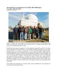
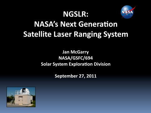
<strong>NGSLR</strong>:<br />
<strong>NASA</strong>’s Next Genera1on<br />
Satellite Laser Ranging System<br />
Jan McGarry<br />
<strong>NASA</strong>/GSFC/694<br />
Solar System Explora1on Division<br />
September 27, 2011
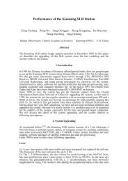
Overview<br />
<strong>NGSLR</strong> is a high repe//on rate single photon<br />
detec/on laser ranging system capable of tracking<br />
cube corner reflector (CCR) equipped satellites in<br />
Earth orbit. The concept of <strong>NGSLR</strong> was developed<br />
by J. Degnan (GSFC, re/red) in the 1990s. Technical<br />
development con/nues at Goddard. The system<br />
has demonstrated tracking of Earth orbit satellites<br />
with al/tudes from ~ 1000 km to 20000 km.<br />
Comple/on of the <strong>NGSLR</strong> prototype will occur<br />
during the Space Geodesy Proposal.<br />
OMC ranging plot of satellite returns<br />
Four<br />
quadrant<br />
satellite<br />
returns<br />
System Features:<br />
1 to 2 arcsecond poin/ng/tracking<br />
accuracy<br />
Track CCR equipped satellites to 20,000<br />
km al/tude, 24/7 opera/on<br />
Reduced ocular, chemical, electrical<br />
hazards<br />
Semi automated tracking features<br />
Small, compact, low maintenance,<br />
increased reliability<br />
Lower opera/ng/replica/on costs<br />
2
Team<br />
John Annen (automa/on lab lead, hardware development) -‐ GSFC/693<br />
Jack Cheek (soXware lead, sysadmin, real-‐/me soXware) -‐ SigmaSpace<br />
Bart Clarke (soXware: OD, SLR data analysis, signal processing) -‐ Honeywell<br />
John Degnan (lasers, SLR theory, original SLR2000 concept) -‐ SigmaSpace<br />
Bud Donovan (hardware lead, deputy <strong>NGSLR</strong> lead, laser safety) – Honeywell<br />
Felipe Hall (documenta/on lead) – Honeywell<br />
Evan Hoffman (hardware development & sustaining engineering) -‐ Honeywell<br />
Julie Horvath (config control & colloca/on lead, i/f with ILRS) -‐ Honeywell<br />
Tony Mann (soXware: unix sysadmin, device drivers) -‐ Honeywell<br />
Jan McGarry (<strong>NGSLR</strong> lead, algorithm & soXware development) -‐ GSFC/694<br />
Don PaVerson (hardware develop., sustaining & system engineering) -‐ Honeywell<br />
Randy Ricklefs (soXware & OS, device drivers, algorithm) – Cybioms<br />
Mark Torrence (SLR analysis) -‐ SGT<br />
Tom Varghese (system engineering) – Cybioms<br />
ScoV Wetzel (cross-‐SGP integra/on) -‐ Honeywell<br />
Tom Zagwodzki (system engineering) -‐ Cybioms<br />
Combined total of > 250 years<br />
SLR experience<br />
SGP 9/27/2011 jlfm 3
Historically Important Dates<br />
<strong>NGSLR</strong> was originally called SLR2000<br />
1994: Original SLR2000 concept, limited to LAGEOS (< 8500 km slant range) and lower satellites, was<br />
first presented to, and endorsed by, the <strong>NASA</strong> Belmont SLR Workshop.<br />
1997: SLR2000 technical approach reviewed and approved by GSFC MTPE Office (Dr. Robert Price). First<br />
substan/al funding provided.<br />
2000: Revised 2000 ANSI laser safety standards for subnanosecond pulses have major impact on<br />
maximum transmiied energy and minimum pulsewidth affec/ng both receive signal strength and single<br />
shot range accuracy.<br />
2001: All major subsystem tests completed successfully.<br />
2002: Prototype system assembled and ready for field tests. Phase III laser on order from Q-‐Peak.<br />
2003: Visual tracking of sunlit satellites demonstrated. Two to three arcsecond star calibra/ons<br />
rou/nely achieved.<br />
2004: LEO satellite tracking demonstrated under operator control.<br />
2006: Many automated subsystems (variable beam expander, PRF, upgraded sky and star cameras) are<br />
integrated and opera/onal except for transmiier point ahead and quadrant detector poin/ng<br />
correc/on.<br />
2008: Night tracks of GLONASS demonstrated with eye-‐safe laser. System mods begun for intermiient<br />
tracking of Lunar Reconnaissance Orbiter (LRO) with high power laser.<br />
2009: Robust day/night tracking of LAGEOS and night tracks of GNSS satellites (GLONASS, Etalon) with<br />
eyesafe laser and transmiier point-‐ahead capability demonstrates original goals of SLR2000<br />
development.<br />
2010: New in-‐house built mJ laser installed, replacing eye-‐safe Q-‐Peak laser.<br />
2011: SGP starts its 2-‐year effort, major funding received.<br />
SGP 9/27/2011 jlfm 4
Original Goals*<br />
“…the primary technical goals of the SLR 2000 system are:<br />
Unmanned, eyesafe opera/on<br />
24 hour tracking of LAGEOS and lower satellites<br />
One cen/meter (RMS) single shot precision or beier<br />
Minimum 100 ranges per normal point<br />
Mean /me between failures: > 4 months<br />
Automated two-‐way communica/ons with a central data processor<br />
via Internet<br />
System free of op/cal, electrical, and chemical hazards<br />
Secondary goals for the system, presently viewed as highly desirable but<br />
perhaps difficult to achieve, include a capability to range to high al/tude<br />
satellites such as GPS, GLONASS, and ETALON and the ability to retrofit two<br />
color technology at some later date.”<br />
*Extracted verba/m from J.J. Degnan, “SLR 2000: An autonomous and eyesafe satellite<br />
laser ranging sta/on “, Proc. Ninth Interna/onal Workshop on Laser Ranging<br />
Instrumenta/on, pp. 312-‐323, Canberra, Australia, November 7-‐11, 1994.<br />
SGP 9/27/2011 jlfm 5
Current Requirements<br />
▪ 24 hour tracking of LEO, LAGEOS & GNSS satellites<br />
(that have ILRS approved retro-‐reflector lidar cross sec/ons)<br />
▪ One millimeter normal point precision on LAGEOS<br />
▪ Accuracy and stability at the MOBLAS level or beier<br />
▪ Semi-‐autonomous opera/ons<br />
▪ Radar for all satellite ranging<br />
▪ Mean /me between failures: > 4 months<br />
SGP 9/27/2011 jlfm 6
SYSTEM Description<br />
SGP 9/27/2011 jlfm 7
1. Time & Frequency<br />
2. Telescope<br />
3. Transceiver Bench<br />
4. Laser<br />
5. Laser Hazard Reduc1on<br />
System (LHRS)<br />
Major Subsystems<br />
6. Tracking<br />
7. Receiver<br />
8. Computer and Sofware<br />
9. Weather<br />
10. Shelter and Dome<br />
8
<strong>NGSLR</strong> System Characteris1cs<br />
• Telescope:<br />
-‐ 40 cm Telescope Aperture Off-‐Axis Parabola<br />
-‐ No Central Obscura/on<br />
• Tracking:<br />
-‐ AZ/EL with 1 arcsec RMS gimbal poin/ng accuracy<br />
• Transceiver Bench:<br />
-‐ Common Op/cs for Transmit and Receive<br />
-‐ Passive Transmit/Receive Switch<br />
-‐ Risley Prism Point-‐Ahead of Transmit<br />
• Laser:<br />
-‐ Subnanosecond pulse, 2 kHz<br />
-‐ Asynchronous PRF, soXware controlled<br />
-‐ Divergence control by soXware<br />
• Receiver:<br />
-‐ High QE, GaAsP Microchannel Plate Photomul/plier<br />
-‐ Constant Frac/on Discriminators<br />
-‐ GPS-‐synchronized Rubidium Oscillator /Time and<br />
Frequency Receiver<br />
-‐ Picosecond Precision Event Timer<br />
• Weather:<br />
-‐ Day/Night All-‐Sky Cloud Sensor (thermal)<br />
-‐ Wind Monitor<br />
-‐ Surface Pressure, Temperature, and Humidity Monitors<br />
-‐ Visibility/Precipita/on Sensor SGP 9/27/2011 jlfm 9
<strong>NGSLR</strong> System Block Diagram<br />
SGP 9/27/2011 jlfm<br />
10
Current Op1cal Bench Layout<br />
SGP 9/27/2011 jlfm 11
Sofware/Computer Overview<br />
▪ Computers:<br />
-‐ Pseudo Operator (POP) – performs operator decisions<br />
-‐ Device Access Manager (DAM) – op/cal bench controller<br />
-‐ Interface & Control Computer (ICC) – real-‐/me data I/O<br />
-‐ Remote Access Terminal (RAT) – interface to human<br />
-‐ Analysis Computer (ANA) – post-‐processing<br />
-‐ Camera computer – start and sky camera interface<br />
-‐ Dome controller – slaves dome to telescope during opera/ons<br />
▪ Backplanes: VME, PCI, ISA.<br />
▪ SoXware<br />
-‐ Opera/ng systems: LynxOS, Linux, Windows, DOS<br />
-‐ Languages: “C”, assembly, perl.<br />
-‐ Lines of code: ~200,000<br />
SGP 9/27/2011 jlfm 12
<strong>NGSLR</strong> Computer Interfaces<br />
SGP 9/27/2011 jlfm 13
Computer & Equipment Racks<br />
SGP 9/27/2011 jlfm<br />
14
Automa1on Overview<br />
(some of the func1ons that will be performed by sofware)<br />
• Obtaining input files:<br />
-‐ automa/cally pull predic/on and other data files from the server.<br />
• System scheduling:<br />
-‐ soXware completely determines/controls what is tracked and when.<br />
• Operator decision making:<br />
-‐ open/close dome based on weather,<br />
-‐ keep telescope from poin/ng into the sun,<br />
-‐ determine if we can track and where in the sky based on cloud cover.<br />
• Signal processing and closed-‐loop tracking:<br />
-‐ determine if system is hitng the satellite,<br />
-‐ search for the satellite and op/mize the poin/ng.<br />
• Transmit / receive path op1cs configura1on and control:<br />
-‐ determine and control op/cal bench configura/on,<br />
-‐ decide configura/on based on target, day/night.<br />
• Data processing and product delivery: normal points delivered hourly.<br />
SGP 9/27/2011 jlfm 15
New Technologies Developed for <strong>NGSLR</strong><br />
The requirements of SLR2000 (i.e. eye safety and unmanned opera1on) led to<br />
a number of unique computer-‐controlled hardware devices including:<br />
• Totally Passive Transmit/Receive Switch allows the full aperture of the telescope to be<br />
shared simultaneously , with minimal op/cal loss, by the transmiier (for eye safety) and<br />
receiver (for signal strength) independent of the laser repe//on rate and receive signal<br />
polariza/on.<br />
• TransmiVer Beam Expander allows the transmiier beam divergence to be varied as a<br />
func/on of satellite range for enhanced signal strength while maintaining a fixed beam<br />
diameter at the telescope exit window for eye safety.<br />
• Variable Spectral Filter op/mizes the filter transmission and spectral bandwidth for<br />
daylight, twilight, and night opera/ons.<br />
• Dual Risley Prism Device permits independent arcsecond accuracy poin/ng of the<br />
transmiier and receiver allowing smaller receiver fields-‐of view for reduced solar noise.<br />
• Variable Iris Spa1al Filter allows adjustment of the receive FOV for less solar noise.<br />
SGP 9/27/2011 jlfm 16
New Technologies Developed for <strong>NGSLR</strong><br />
(con1nued)<br />
• Variable Laser Trigger varies laser repe//on rate about the nominal 2 kHz to prevent<br />
backscaier from the outgoing laser pulse from overlapping satellite returns at receiver.<br />
• Dual Liquid Crystal Op1cal Gates further reduces laser instrument and atmospheric<br />
backscaier by more than two orders of magnitude, independent of polariza/on.<br />
• Smart Meteorological Sta1on monitors hemispherical cloud cover and ground visibility<br />
(to support satellite selec/on and efficient opera/ons), precipita/on (for system<br />
protec/on), wind speed and direc/on, while providing the usual atmospheric surface<br />
pressure, temperature, and rela/ve humidity measurements needed to support<br />
atmospheric refrac/on correc/ons to the range measurements.<br />
• Algorithms and related sofware to give <strong>NGSLR</strong> the ability to autonomously (1)<br />
determine when and how to change the laser pulse repe//on frequency (PRF) to avoid<br />
collision between outgoing and incoming laser pulses, (2) process returns to find satellite<br />
events in very low signal to noise environments, (3) con/nually monitor the angular<br />
proximity of the telescope to the sun and move the mount to avoid getng sunlight into<br />
the detector, (4) direct the transmit beam as an angular offset from the telescope to put<br />
laser pulses where the satellite will be when the light arrives.<br />
SGP 9/27/2011 jlfm 17
STATUS<br />
SGP 9/27/2011 jlfm 18
Original System Configura1on<br />
Q-‐Peak Laser and Photek QMCP<br />
Q-‐Peak Laser:<br />
• Model MPV-‐2000, doubled YVO 4<br />
• 200 µJ, 532 nm, 350 ps, 2 kHz, 0.9 x 1.8 mR,<br />
1.1 x 0.5 mm Ø<br />
• Ra1onale for Replacement<br />
-‐Laser performance degraded – energy decreased<br />
from 200 µJ to 60 µJ<br />
-‐Day1me GNSS tracking requirement<br />
necessitated increased energy<br />
Photek QMCP Installa1on:<br />
• Quadrant Anode, 12% QE, 140 ps t r<br />
• Ra1onale for Replacement<br />
-‐QE decreased from 12% to 30%<br />
SGP 9/27/2011 jlfm 19
<strong>NGSLR</strong> Performance with Q-‐Peak Laser<br />
• Q-‐Peak Laser<br />
-‐Low energy/eye-‐safe<br />
-‐2KHz repe11on rate<br />
-‐350 ps pulsewidth<br />
• <strong>NGSLR</strong> Successful Tracking with Q-‐Peak Laser<br />
-‐LEO (day/night):<br />
BEC, Jason, Ajisai, StarleVe, Stella<br />
-‐Lageos 1 & 2 (day/night)<br />
-‐HEO (night)<br />
Etalon, GLONASS<br />
• <strong>NGSLR</strong> System Performance<br />
-‐Ground Cal RMS: 20mm<br />
-‐Lageos Single Shot RMS: 40 mm<br />
-‐Lageos Normal Point RMS: mm’s<br />
-‐Ground cal stability: +/-‐ 5mm<br />
-‐Bias between <strong>NGSLR</strong> and MOB-‐7: ~2 cm<br />
SGP 9/27/2011 jlfm 20
Current Automa1on Status<br />
▪ Completed, tested and working<br />
-‐ Automated star calibra/on<br />
-‐ Sun avoidance (soXware)<br />
-‐ Laser pulse collision avoidance<br />
-‐ Point-‐ahead tracking using Risley Prisms<br />
-‐ Obtaining input data and system scheduling<br />
▪ Almost complete<br />
-‐ Open/close of dome based on weather<br />
-‐ Determina/on what can be tracked based on cloud cover<br />
-‐ Determina/on if system is hitng the satellite<br />
-‐ Search for the satellite if not getng signal returns<br />
-‐ Normal point genera/on and data delivery<br />
▪ Being worked<br />
-‐ Remaining op/cal bench motor controls<br />
-‐ New I/O chassis soXware interface<br />
-‐ Closed loop tracking (op/mizing biases during tracking)<br />
-‐ Fully automated ground calibra/on<br />
SGP 9/27/2011 jlfm 21
<strong>NGSLR</strong> Documenta1on<br />
• Produc1on of Documenta1on is proceeding as planned<br />
• All cri1cal documenta1on will be updated before December 2012, documen1ng the <strong>NGSLR</strong> system<br />
in its final state.<br />
SGP 9/27/2011 jlfm 22
The Path to Completion<br />
SGP 9/27/2011 jlfm 23
Configura1on for Intercomparison with MOB-‐7<br />
▪ Laser and detector:<br />
-‐ <strong>NASA</strong> in-‐house built laser (Poulios & Coyle): ~ 1 mJ per pulse, 200 ps pulsewidth<br />
-‐ Variable rep rate (nominally 2 kHz), variable transmit energy<br />
-‐ Hamamatsu high QE MCP detector<br />
-‐ Expect a factor of 20x improvement over Q-‐Peak configura/on<br />
▪ Tracking performance for period Dec 2010 – July 2011:<br />
-‐ Successfully tracked LEOs, LAGEOS and GLONASS at night<br />
-‐ Return rates were higher than with Q-‐Peak<br />
-‐ Was not able to range during daylight – due to wavelength instability and<br />
mismatch with daylight filter<br />
▪ In-‐house laser issues currently being worked in B33 lab:<br />
-‐ Internal damage from high energy density on laser op/cs (this has been fixed)<br />
-‐ Stability issues (purchased new seeder to eliminate wavelength instability)<br />
-‐ Comes back shortly to <strong>NGSLR</strong> to allow us to con/nue development efforts and<br />
performance improvements, and to establish a baseline for system tracking /<br />
ranging performance<br />
SGP 9/27/2011 jlfm 24
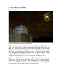
In-‐house built 2 kHz laser<br />
Regenera/ve amplifier seeded by a gain-‐switched diode laser<br />
Nd:YAG slabs<br />
1.5m folded<br />
cavity<br />
Seeder<br />
KTP doubler<br />
Pockels cell<br />
SGP 9/27/2011 jlfm 25
Bias (mm)<br />
Data Rate (%)<br />
3<br />
2<br />
1<br />
0<br />
-1<br />
-2<br />
-3<br />
6<br />
5<br />
4<br />
3<br />
2<br />
1<br />
0<br />
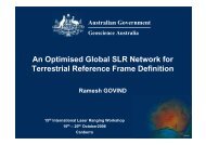
System Stability Results<br />
Ground calibra/on data using Photek quadrant detector<br />
Ground Cal-Ch1, Ch 2, Ch3, -(Ch1+2+3)/3-2kHz-Photek MCP-PMT-75min - Stability: March 23-2011-d82-t1336<br />
48600 48900 49200 49500 49800 50100 50400 50700 51000 51300 51600 51900 52200 52500 52800 53100 53400 53700<br />
Time (secs)<br />
Q1 Q2 Q3 (Q1+Q2+Q3)/3<br />
Ground Cal-1mJ Laser-Ch1, 2,3,4-2000 Hz-Photek MCP-PMT- 75 min - Stability: March 23-2011-d82<br />
Q1 Q4 q2 q3<br />
48600 48900 49200 49500 49800 50100 50400 50700 51000 51300 51600 51900 52200 52500 52800 53100 53400 53700<br />
Time (secs)<br />
• External Cal Data Session Stability: Plot of External Cal Residual (millimeter) and Data Rate (%) vs. Time for a duration of<br />
75 minutes; 4th channel (BLACK line) in the upper plot shows the mean of 3 channels; Lower plot shows the data rates for<br />
each of the Q1 thru Q4 Channels; Horizontal scale is 5 minutes<br />
SGP 9/27/2011 jlfm 26
<strong>NGSLR</strong> Automa1on Laboratory<br />
• Development Efforts in Lab<br />
-‐Development of new op/cal bench layout<br />
-‐Design and tes/ng of specialized moun/ng hardware for op/cs<br />
-‐Verifica/on of selected op/cal components<br />
-‐Design and verifica/on of alignment aids and alignment procedure<br />
-‐Assembly and alignment of new op/cal bench<br />
-‐Verifica/on and Tes/ng of COTS high energy, short pulse laser<br />
-‐Integra/on of COTS laser onto op/cal bench<br />
• Benefits of Lab Work<br />
-‐Introduce a fully automated layout<br />
-‐Isolate transmit/receive path on the bench to reduce system noise<br />
-‐Improve access to all devices for alignment<br />
-‐Upgrade alignment procedure<br />
-‐Increase system efficiency<br />
-‐Allows work to go on without disturbing <strong>NGSLR</strong> tracking<br />
Once aligned and tested, the new bench will be moved into the <strong>NGSLR</strong><br />
shelter, accelera;ng the integra;on process<br />
SGP 9/27/2011 jlfm 27
New Op1cal Bench<br />
preliminary design<br />
SGP 9/27/2011 jlfm 28
IO Chassis<br />
• Controls and distributes the proper gate signals for the PMT and discriminator<br />
during ground calibra/ons and satellite tracking using its internal delay circuits<br />
and the RGG inputs as well as electronics for the MCP blanking circuit.<br />
• Contains electronics and firmware enabling computer interface and control and/<br />
or monitoring of various hardware on the Op/cal Bench such as beam blocks,<br />
op/cal density filters, shuiers, gradient ND filter wheels, etc.<br />
• Provides interface electronics for the Remote Control Box which allows manual<br />
control of various elements on the Op/cal Bench for maintenance and alignment<br />
purposes.<br />
• Serves as the safety interlock chassis providing power and control to beam blocks<br />
when a safety condi/on occurs such as an aircraX detect, opening of the Shelter<br />
door, and unauthorized access of the stairway to the telescope area.<br />
• Provides the interface electronics for the control of the radar subsystem.<br />
SGP 9/27/2011 jlfm<br />
29
Sofware Development and Tes1ng<br />
(Using <strong>NGSLR</strong> Automa1on Lab)<br />
• Facilitates the development of new software without disturbing the<br />
operational system and serves as a test location for operational spare<br />
computers.<br />
• Uses a complete set of duplicate computers, motor controllers, an optical<br />
bench, and an IO chassis (both a software simulator and a hardware setup).<br />
• Uses software simulators when/where spare components are not available.<br />
• Enables the designing, coding and testing of IO chassis software and<br />
automation control software.<br />
• Permits testing of the automated search and cloud decision software.<br />
• Allows the testing of star assessments, star calibrations, ground calibrations,<br />
satellite tracking as well as “real world” scenarios.<br />
SGP 9/27/2011 jlfm<br />
30
Final System Configura1on<br />
Hamamatsu High QE MCP PMT:<br />
• Model R5916U-‐64<br />
• GaAsP Photocathode<br />
• QE > 43%<br />
• Rise Time
<strong>NGSLR</strong> Colloca1on with MOBLAS-‐7<br />
• What is a Colloca1on?<br />
-‐ Colloca1on is the process of geometrically comparing<br />
ranging data from two or more SLR systems in close<br />
proximity (preferably
SUMMARY<br />
- Most of the original goals for SLR2000 have been achieved.<br />
-‐ Significant progress has been made in performance and automa1on.<br />
-‐ LEO to LAGEOS ranging demonstrated day & night with eye-‐safe energies.<br />
-‐ GNSS tracking demonstrated at night with eye-‐safe energies.<br />
-‐ Major technology developments:<br />
Passive T/R switch, Risleys for point-‐ahead, transmiier beam expander,<br />
smart Met sta/on, liquid crystal op/cal gates, …<br />
-‐ Major sofware achievements:<br />
Sun avoidance soXware, laser PRF changes for pulse collision avoidance,<br />
point-‐ahead angular calcula/ons, signal processing, operator decision<br />
automa/on, …<br />
-‐ <strong>NGSLR</strong> lab has been setup -‐ allowing parallel progress in automa1on,<br />
sofware checkout and system performance.<br />
-‐ Significant progress on documenta1on – have ini1al version of several<br />
major system documents & drawings.<br />
Most importantly, <strong>NGSLR</strong> has:<br />
-‐ Achievable path to comple;on, and<br />
-‐ Accomplished team with extensive SLR experience. 33