A PVDF-Based Deformation and Motion Sensor ... - IEEE Xplore
A PVDF-Based Deformation and Motion Sensor ... - IEEE Xplore
A PVDF-Based Deformation and Motion Sensor ... - IEEE Xplore

Create successful ePaper yourself
Turn your PDF publications into a flip-book with our unique Google optimized e-Paper software.
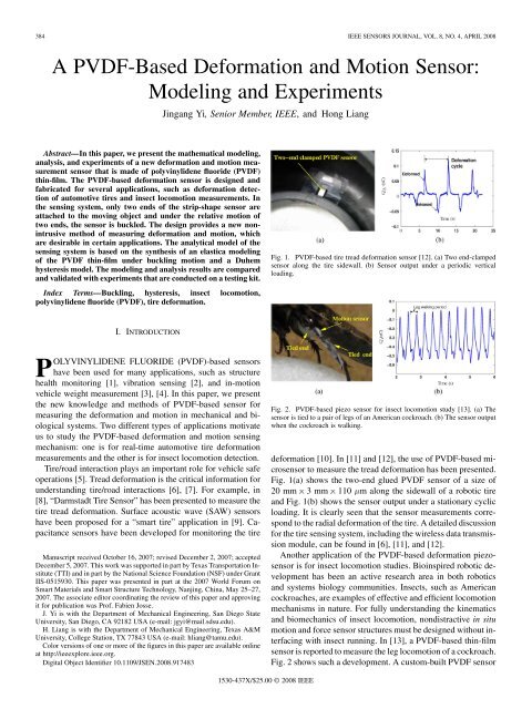
384 <strong>IEEE</strong> SENSORS JOURNAL, VOL. 8, NO. 4, APRIL 2008<br />
A <strong>PVDF</strong>-<strong>Based</strong> <strong>Deformation</strong> <strong>and</strong> <strong>Motion</strong> <strong>Sensor</strong>:<br />
Modeling <strong>and</strong> Experiments<br />
Abstract—In this paper, we present the mathematical modeling,<br />
analysis, <strong>and</strong> experiments of a new deformation <strong>and</strong> motion measurement<br />
sensor that is made of polyvinylidene fluoride (<strong>PVDF</strong>)<br />
thin-film. The <strong>PVDF</strong>-based deformation sensor is designed <strong>and</strong><br />
fabricated for several applications, such as deformation detection<br />
of automotive tires <strong>and</strong> insect locomotion measurements. In<br />
the sensing system, only two ends of the strip-shape sensor are<br />
attached to the moving object <strong>and</strong> under the relative motion of<br />
two ends, the sensor is buckled. The design provides a new nonintrusive<br />
method of measuring deformation <strong>and</strong> motion, which<br />
are desirable in certain applications. The analytical model of the<br />
sensing system is based on the synthesis of an elastica modeling<br />
of the <strong>PVDF</strong> thin-film under buckling motion <strong>and</strong> a Duhem<br />
hysteresis model. The modeling <strong>and</strong> analysis results are compared<br />
<strong>and</strong> validated with experiments that are conducted on a testing kit.<br />
Index Terms—Buckling, hysteresis, insect locomotion,<br />
polyvinylidene fluoride (<strong>PVDF</strong>), tire deformation.<br />
I. INTRODUCTION<br />
POLYVINYLIDENE FLUORIDE (<strong>PVDF</strong>)-based sensors<br />
have been used for many applications, such as structure<br />
health monitoring [1], vibration sensing [2], <strong>and</strong> in-motion<br />
vehicle weight measurement [3], [4]. In this paper, we present<br />
the new knowledge <strong>and</strong> methods of <strong>PVDF</strong>-based sensor for<br />
measuring the deformation <strong>and</strong> motion in mechanical <strong>and</strong> biological<br />
systems. Two different types of applications motivate<br />
us to study the <strong>PVDF</strong>-based deformation <strong>and</strong> motion sensing<br />
mechanism: one is for real-time automotive tire deformation<br />
measurements <strong>and</strong> the other is for insect locomotion detection.<br />
Tire/road interaction plays an important role for vehicle safe<br />
operations [5]. Tread deformation is the critical information for<br />
underst<strong>and</strong>ing tire/road interactions [6], [7]. For example, in<br />
[8], “Darmstadt Tire <strong>Sensor</strong>” has been presented to measure the<br />
tire tread deformation. Surface acoustic wave (SAW) sensors<br />
have been proposed for a “smart tire” application in [9]. Capacitance<br />
sensors have been developed for monitoring the tire<br />
Manuscript received October 16, 2007; revised December 2, 2007; accepted<br />
December 5, 2007. This work was supported in part by Texas Transportation Institute<br />
(TTI) <strong>and</strong> in part by the National Science Foundation (NSF) under Grant<br />
IIS-0515930. This paper was presented in part at the 2007 World Forum on<br />
Smart Materials <strong>and</strong> Smart Structure Technology, Nanjing, China, May 25–27,<br />
2007. The associate editor coordinating the review of this paper <strong>and</strong> approving<br />
it for publication was Prof. Fabien Josse.<br />
J. Yi is with the Department of Mechanical Engineering, San Diego State<br />
University, San Diego, CA 92182 USA (e-mail: jgyi@mail.sdsu.edu).<br />
H. Liang is with the Department of Mechanical Engineering, Texas A&M<br />
University, College Station, TX 77843 USA (e-mail: hliang@tamu.edu).<br />
Color versions of one or more of the figures in this paper are available online<br />
at http://ieeexplore.ieee.org.<br />
Digital Object Identifier 10.1109/JSEN.2008.917483<br />
Jingang Yi, Senior Member, <strong>IEEE</strong>, <strong>and</strong> Hong Liang<br />
1530-437X/$25.00 © 2008 <strong>IEEE</strong><br />
Fig. 1. <strong>PVDF</strong>-based tire tread deformation sensor [12]. (a) Two end-clamped<br />
sensor along the tire sidewall. (b) <strong>Sensor</strong> output under a periodic vertical<br />
loading.<br />
Fig. 2. <strong>PVDF</strong>-based piezo sensor for insect locomotion study [13]. (a) The<br />
sensor is tied to a pair of legs of an American cockroach. (b) The sensor output<br />
when the cockroach is walking.<br />
deformation [10]. In [11] <strong>and</strong> [12], the use of <strong>PVDF</strong>-based microsensor<br />
to measure the tread deformation has been presented.<br />
Fig. 1(a) shows the two-end glued <strong>PVDF</strong> sensor of a size of<br />
20 mm 3mm 110 m along the sidewall of a robotic tire<br />
<strong>and</strong> Fig. 1(b) shows the sensor output under a stationary cyclic<br />
loading. It is clearly seen that the sensor measurements correspond<br />
to the radial deformation of the tire. A detailed discussion<br />
for the tire sensing system, including the wireless data transmission<br />
module, can be found in [6], [11], <strong>and</strong> [12].<br />
Another application of the <strong>PVDF</strong>-based deformation piezosensor<br />
is for insect locomotion studies. Bioinspired robotic development<br />
has been an active research area in both robotics<br />
<strong>and</strong> systems biology communities. Insects, such as American<br />
cockroaches, are examples of effective <strong>and</strong> efficient locomotion<br />
mechanisms in nature. For fully underst<strong>and</strong>ing the kinematics<br />
<strong>and</strong> biomechanics of insect locomotion, nondistractive in situ<br />
motion <strong>and</strong> force sensor structures must be designed without interfacing<br />
with insect running. In [13], a <strong>PVDF</strong>-based thin-film<br />
sensor is reported to measure the leg locomotion of a cockroach.<br />
Fig. 2 shows such a development. A custom-built <strong>PVDF</strong> sensor
YI AND LIANG: A <strong>PVDF</strong>-BASED DEFORMATION AND MOTION SENSOR: MODELING AND EXPERIMENTS 385<br />
of size 10 mm 1mm 28 m is tied to a pair of legs of a cockroach<br />
[Fig. 2(a)] <strong>and</strong> the sensor output is connected through a<br />
thin wire (0.3 mm diameter) to an on-board charge amplifier for<br />
voltage measurements. Fig. 2(b) shows the sensor output when<br />
the cockroach is walking. Some results have shown a correlation<br />
between the sensor output <strong>and</strong> the insect locomotion [13].<br />
In both applications discussed above, the <strong>PVDF</strong> sensors are<br />
clamped at two ends. Under the relative movement of the two<br />
sensor ends, the <strong>PVDF</strong> thin-film is buckled <strong>and</strong> sensors generate<br />
electric charge due to bending motion. Such a new sensing design<br />
is different with most <strong>PVDF</strong>-based sensing applications.<br />
Most <strong>PVDF</strong>-based applications utilize the high piezoelectricity<br />
<strong>and</strong> reliability of the <strong>PVDF</strong> material for sensor design [14]. In<br />
these applications, the <strong>PVDF</strong> sensor film is glued on or embedded<br />
inside the sensed objects <strong>and</strong> typically the deformation<br />
is not large. For large deformation applications, such as<br />
vibration sensing in [2], the <strong>PVDF</strong> film is clamped on a fixed<br />
foundation. To the authors’ knowledge, besides the two applications<br />
that we mentioned in this paper, there is few discussions<br />
for <strong>PVDF</strong>-based large deformation <strong>and</strong> motion sensing<br />
<strong>and</strong> measurement.<br />
The goal of this paper is to develop <strong>and</strong> validate an analytical<br />
model for the <strong>PVDF</strong>-based deformation <strong>and</strong> movement sensors.<br />
The analytical models will provide a quantitative relationship<br />
between the sensor measurements <strong>and</strong> the deformation or motion<br />
information of the two sensor ends <strong>and</strong>, thus, facilitate the<br />
sensor applications. There are a large amount of research work<br />
that study the constitutive relationship between the mechanical<br />
forces (moments) <strong>and</strong> electrical voltage (charge) for multilayer<br />
beamed piezoelectric materials. Readers can refer to [14] <strong>and</strong><br />
[15] <strong>and</strong> the references therein. We cannot, however, apply the<br />
existing analytical results to model the <strong>PVDF</strong>-based large deformation<br />
sensors in our applications for several reasons. First,<br />
most modeling work of piezoelectric materials are based on<br />
beam theory <strong>and</strong> small deflections or deformations are typically<br />
the underlying assumptions. Second, in most piezo-based<br />
sensing applications, the sensors are either glued on surfaces or<br />
embedded inside mechanical or civil structures, while for our<br />
applications only two ends of the <strong>PVDF</strong> sensors are attached to<br />
moving objects <strong>and</strong> the main body of the <strong>PVDF</strong> thin-film are<br />
freely deformed.<br />
We take a different approach to consider the <strong>PVDF</strong> sensor as<br />
a thin strip for modeling purposes because of the high aspect<br />
ratios in geometry (thin <strong>and</strong> long) of the sensor design. Typical<br />
Euler-type buckling models cannot capture the deformation <strong>and</strong><br />
shape of such a thin heavy strip. Instead, a heavy elastica model<br />
[16], [17] is utilized to describe the deflection of the post-buckling<br />
shape of the sensor film. We consider the strain (stress)<br />
distribution among the <strong>PVDF</strong> elastica under the buckling motion<br />
<strong>and</strong> the generated electric charge is then estimated using the<br />
constitutive piezoelectric relationship [18]. A hysteresis model<br />
is employed to capture the phase-shift nonlinear phenomena in<br />
piezoelectric materials. We finally develop a testing kit to validate<br />
the sensor modeling <strong>and</strong> analysis.<br />
The remainder of this paper is organized as follows. In<br />
Section II, we present an analytical model for the <strong>PVDF</strong><br />
sensors under a buckling motion. Experimental comparison<br />
<strong>and</strong> model validation of the deformation sensors are presented<br />
Fig. 3. (a) A schematic of the buckling shape of a <strong>PVDF</strong> based heavy elastica<br />
sensor. (b) A free body diagram of the differential element of the elastica.<br />
in Section III. The concluding remarks <strong>and</strong> future research<br />
directions are included in Section IV.<br />
II. SENSOR MODELS<br />
In this section, we first consider the output model for charge<br />
that is purely generated by the mechanical buckling motion<br />
of the <strong>PVDF</strong> film. Then, we present a hysteresis model to capture<br />
the nonlinear property of the <strong>PVDF</strong> piezo-materials. If we<br />
denote the hysteresis operator as , the sensor output charge<br />
is considered as .<br />
A. <strong>Sensor</strong> Buckling <strong>Motion</strong> <strong>and</strong> Charge Calculation<br />
For the buckling sensors shown in Figs. 1 <strong>and</strong> 2, we denote<br />
the sensor size as (length), (width), <strong>and</strong> (height), respectively.<br />
We consider a <strong>PVDF</strong>-based buckling elastica shown<br />
in Fig. 3(a). One end of the <strong>PVDF</strong> elastica is clamped at a fixed<br />
platform <strong>and</strong> the other end is clamped with a moving platform.<br />
The deformation of the moving end is denoted as <strong>and</strong> the<br />
applied force is denoted as . We here consider that the deflection<br />
is measured from the position where the <strong>PVDF</strong><br />
thin-film is flat, namely, initially the <strong>PVDF</strong> thin-film is flat <strong>and</strong><br />
.<br />
We choose the coordinate with the origin at the middle<br />
point of the <strong>PVDF</strong> elastica. The deflection at point<br />
is parameterized by the arc-length (with at point<br />
), as shown in Fig. 3(a). The deflection angle is defined<br />
as the tangent directional angle with the axis. Fig. 3(b)
386 <strong>IEEE</strong> SENSORS JOURNAL, VOL. 8, NO. 4, APRIL 2008<br />
shows the free body diagram of a differential element at<br />
point . The internal forces along the <strong>and</strong> directions on<br />
the differential element at time are denoted as<br />
<strong>and</strong> , respectively. The bending moment at point is<br />
denoted as at time . Similar to the developments in [16]<br />
<strong>and</strong> [17], we obtain the motion equations for the <strong>PVDF</strong> elastica<br />
as 1<br />
where is Young’s modulus of the <strong>PVDF</strong> film, is the second<br />
moment inertia of the cross sectional area of the elastica with<br />
respect to the bending axis, is the curvature, <strong>and</strong><br />
is the mass density per unit length of the <strong>PVDF</strong> strip.<br />
Before we proceed to put (1) into dimensionless equations,<br />
we first determine the electric charge due to the sensor<br />
buckling motion. The accumulated electric charge can be<br />
calculated as [18]<br />
where is electric displacement along the 3 (vertical) direction,<br />
is the strain along the 1 (longitudinal) direction, is the<br />
electrode area of the strip surface, is the <strong>PVDF</strong> piezoelectric<br />
constant between the 3 <strong>and</strong> 1 directions, is the stiffness<br />
constant of the <strong>PVDF</strong> film along the 1 direction. For the definition<br />
of the strain (stress) <strong>and</strong> electrical fields direction for the<br />
piezo-material [the 123 axes shown in Fig. 3(a)], readers can<br />
refer to [18] <strong>and</strong> [19].<br />
We consider that the electric charge is mainly generated by<br />
the bending of the <strong>PVDF</strong> film. For the differential <strong>PVDF</strong> element<br />
shown in Fig. 3(b), the element is under both bending <strong>and</strong><br />
axial force <strong>and</strong> the neutral axis [ in Fig. 3(b)] is no longer<br />
the film centriodal axis [ in Fig. 3(b)]. Denote the distance<br />
between <strong>and</strong> as at location <strong>and</strong> time . Then,<br />
the axial force along the sensor film is given by<br />
<strong>and</strong> the bending moment is . Note that the strain along<br />
<strong>and</strong> using the superposition of axial force <strong>and</strong> bending<br />
moment effects, we can calculate as<br />
Then, the strain of the <strong>PVDF</strong> film is calculated as<br />
1 For notation simplicity, we drop the variable dependence on arc-length ƒ<br />
<strong>and</strong> time in the rest of this paper.<br />
(1)<br />
(2)<br />
(3)<br />
(4)<br />
where we use for a rectangular cross section<br />
area. Due to the symmetry of the film, we only consider the half<br />
portion , <strong>and</strong> thus write (2) as<br />
We define the following nondimensional quantities:<br />
where is the motion frequency. With the nondimensional<br />
quantities, (1) can be written as<br />
Furthermore, we separate the variables as the sum of equilibrium<br />
<strong>and</strong> dynamic components, namely<br />
where the symbols with subscriptions “ ” represent the (time<br />
independent) equilibrium components <strong>and</strong> symbols with subscriptions<br />
“ ” represent the dynamic components that are part<br />
of time-dependent terms.<br />
We then write the equations that the equilibrium components<br />
must be satisfied as<br />
The normalized force satisfies since is the<br />
normalized gravity force from . The boundary conditions<br />
for (7) are<br />
(5)<br />
(6)<br />
(7)<br />
(8a)<br />
(8b)<br />
We consider the charge generated by the quasi-static equilibria<br />
<strong>and</strong>, therefore, we write (5) as<br />
(9)
YI AND LIANG: A <strong>PVDF</strong>-BASED DEFORMATION AND MOTION SENSOR: MODELING AND EXPERIMENTS 387<br />
B. Charge Approximation<br />
The exact analytical solutions for the differential (7) with the<br />
boundary conditions (8) cannot be obtained [16]. Therefore,<br />
we instead approximate the solutions for the boundary-value<br />
problem given by (7) <strong>and</strong> (8).<br />
For a small deflection <strong>and</strong> the fact that the flexural<br />
rigidity is a dominant factor for the <strong>PVDF</strong> strip, we assume<br />
for a small . We then approximate each<br />
equilibrium component in (7) as a perturbation of terms<br />
Here, we consider the fact that , <strong>and</strong> are small <strong>and</strong>,<br />
thus, as a sum of odd-power terms of <strong>and</strong> , <strong>and</strong> are as<br />
a sum of even-power terms of [16].<br />
Substituting the above approximations into (7) <strong>and</strong> taking the<br />
first two terms in in each equation, we obtain<br />
The boundary conditions given by (8) can be rewritten as<br />
(10)<br />
(11)<br />
We can solve (10) with the above boundary conditions <strong>and</strong><br />
obtain solutions for <strong>and</strong> as<br />
(12a)<br />
(12b)<br />
where constant is determined by the external force . With<br />
<strong>and</strong> , we can obtain the normalized force from (10) as<br />
<strong>and</strong><br />
For , <strong>and</strong> ,wehave<br />
(13)<br />
The normalized deflection of the moving end of the <strong>PVDF</strong><br />
elastica <strong>and</strong> the maximum height of the <strong>PVDF</strong> elastica deflection<br />
can be calculated as<br />
<strong>and</strong><br />
Using (12) <strong>and</strong> (13), we approximately calculate the electric<br />
charge (9) as<br />
(14)<br />
where in the above approximation, we drop the high-order terms<br />
that contain . Using the relationship ,we<br />
simplify (14) as<br />
(15)<br />
where is a constant. It is noted that<br />
the output charge by the piezoelectric material, such as <strong>PVDF</strong>,<br />
only responses to the dynamic deflection motion . Therefore,<br />
the actual output charge should filter out the dc component in<br />
the above approximation given in (15), namely<br />
<strong>and</strong> if the deflection is small, i.e., , we can further approximate<br />
the charge as<br />
(16)<br />
Equation (16) implies that the charge generated by the dynamic<br />
deflection is proportional to the deflection magnitude. However,<br />
there exists a phase shift between the output charge<br />
<strong>and</strong> the deflection . We are now ready to discuss<br />
how to capture such a nonlinear phase-shift effect.<br />
C. Hysteresis Modeling<br />
The existence of hysteresis between sensor input <strong>and</strong> output<br />
is widely known for piezoelectric sensors [19]. Fig. 4 show the<br />
experimental results for a buckling test of a <strong>PVDF</strong> sensor of a<br />
size of 32 mm 3mm 110 m under a sinusoidal deflection<br />
mm. Fig. 4(a) shows the time-trajectory<br />
<strong>and</strong> Fig. 4(b) shows a hysteresis curve between charge<br />
<strong>and</strong> deflection due to their phase differences.<br />
We consider a Duhem model to capture the rate-independent<br />
hysteresis relationship between the charge outputs <strong>and</strong><br />
[20], [21]. Here, we consider the buckling-generated charge<br />
as the input to the hysteresis operator, namely, .
388 <strong>IEEE</strong> SENSORS JOURNAL, VOL. 8, NO. 4, APRIL 2008<br />
Fig. 4. (a) Measured charge output <strong>and</strong> the cyclic deflection 1@A aR‘0I C<br />
@IH%A“ mm. (b) A hysteresis curve between the charge <strong>and</strong> deflection<br />
1.<br />
The Duhem model represents operator by a first-order<br />
nonlinear differential equation as<br />
(17)<br />
where <strong>and</strong> are model constants that<br />
depend on the shape <strong>and</strong> area of the experimental hysteresis<br />
curves. In (17), the output charge is considered as the state<br />
variable of the differential equation <strong>and</strong> is dependent on the<br />
values of both <strong>and</strong> . Such a mathematical relationship<br />
(17) can reproduce the hysteresis phenomena that we observe in<br />
experiments. Readers can refer to [21] for more details on how<br />
to estimate these hysteresis model parameters.<br />
It is noted that due to the existing hysteresis in <strong>PVDF</strong> piezoelectric<br />
materials, the output charge is a nonlinear function<br />
of the deflection although the calculated charge due<br />
to the buckling motion is linear in , as shown in (16). In<br />
the next section, we will discuss experiments <strong>and</strong> estimation of<br />
model parameters for sensor output charge models.<br />
Fig. 5. (a) A experiment setup for buckling sensor testing. (b) A buckled <strong>PVDF</strong><br />
sensor.<br />
A. Experiment Setup<br />
III. EXPERIMENTS<br />
We have developed a deformation sensor characteristic<br />
testing kit to experimentally capture <strong>and</strong> validate the relationship<br />
between the sensor output charge <strong>and</strong> the deflection. Fig. 5<br />
shows the experiment setup. We use several types of metalized<br />
<strong>PVDF</strong> thin films (from Measurement Specialties, Inc.) with<br />
different thicknesses. The <strong>PVDF</strong> thin-film is fabricated into<br />
different sizes. Thin wires are connected to one end of the<br />
sensor by conductive glue. A computer-controlled linear stage<br />
(Parker MX80S) is used to move one end of the <strong>PVDF</strong> sensor<br />
film to simulate the deflection motion, while the other end of<br />
the sensor is clamped at a stationary fixture. A laser deflection<br />
sensor (Banner LG5) is employed to monitor the deflection<br />
of the <strong>PVDF</strong> thin-film sensor at a fixed location. The linear<br />
stage controller is implemented using a high-performance<br />
servo control board (NI PCI 7350) from National Instruments,<br />
Inc. The controlled motion trajectory is designed through NI<br />
LabView. A data acquisition system (NI PCI 6221) records
YI AND LIANG: A <strong>PVDF</strong>-BASED DEFORMATION AND MOTION SENSOR: MODELING AND EXPERIMENTS 389<br />
Fig. 6. (a) The output charge of a <strong>PVDF</strong> sensor under a sinusoidal deflection<br />
motion with frequencies of 5 <strong>and</strong> 10 Hz <strong>and</strong> a peak amplitude of 8 mm for a<br />
<strong>PVDF</strong> sensor of a size of 32 mm 2 3mm2 110 "m. (b) Output charge peak<br />
values versus excitation frequency under a sinusoidal deflection motion<br />
with a peak amplitude of 2 mm for a <strong>PVDF</strong> sensor of a size of 10 mm 2 1<br />
mm 2 28 "m.<br />
sensor output <strong>and</strong> feedback motion information. The sensor<br />
output is conditioned by a charge amplifier (PCB 422E03)<br />
before the data is sampled through the data acquisition system.<br />
B. Experiment Results<br />
In all experiments, we choose that the peak-to-peak amplitude<br />
of the sinusoidal deflection is around 50% of the sensor<br />
length .Wefirst test the <strong>PVDF</strong> sensor under buckling with<br />
various motion frequencies. Fig. 6(a) shows the output charge<br />
as a function of the deflection under a sinusoidal motion<br />
of two frequencies. The <strong>PVDF</strong> sensor is of a size of 32<br />
mm 3mm 110 m <strong>and</strong> the peak amplitude of the deflection<br />
is 8 mm (peak-to-peak amplitude is 16 mm). From Fig. 6(a),<br />
it is clearly observed a fixed hysteresis pattern under both frequencies.<br />
We also take a smaller size <strong>PVDF</strong> sensor (10 mm 1<br />
mm 28 m) <strong>and</strong> measure the sensor output under a sinusoidal<br />
Fig. 7. Output charge peak values versus deflection peak amplitudes<br />
under a 2 Hz sinusoidal motion for a <strong>PVDF</strong> sensor of a size of<br />
10 mm 2 1mm2 28"m.<br />
Fig. 8. Measured <strong>and</strong> estimated hysteresis curves for a <strong>PVDF</strong> sensor of a size<br />
of 25 mm 2 3mm2 110 "m under a 5 Hz <strong>and</strong> 6 mm peak amplitude sinusoidal<br />
deflection motion.<br />
deflection of a peak amplitude of 2 mm (peak-to-peak amplitude<br />
is 4 mm) with various frequencies. Fig. 6(b) illustrates that the<br />
peak charge values are kept constantly under a varying excitation<br />
frequency from 1 to 10 Hz. These results confirm that the<br />
hysteresis generated by <strong>PVDF</strong> thin-film is independent of the<br />
time scale of the input excitation <strong>and</strong> thus rate-independent.<br />
Fig. 7 shows that the peak values of the sensor output charge<br />
are proportional to the deflection peak amplitude. Such an observation<br />
validates our analysis of the output charge as given by<br />
(16). Note that the linear correlation between the magnitudes of<br />
output charge <strong>and</strong> deflection only shows their peak<br />
value relationship. Due to the existing hysteresis, the instantaneous<br />
relationship between <strong>and</strong> is highly nonlinear<br />
<strong>and</strong> in the following we are going to estimate the hysteresis<br />
model.<br />
Fig. 8 shows a comparison between the measured <strong>and</strong> Duhem<br />
model-based estimated hysteresis curves between <strong>and</strong>
390 <strong>IEEE</strong> SENSORS JOURNAL, VOL. 8, NO. 4, APRIL 2008<br />
TABLE I<br />
ESTIMATED PARAMETERS OF THE DUHEM HYSTERESIS MODEL<br />
AND SENSOR MODEL<br />
Fig. 9. (a) Measured <strong>and</strong> model estimated charge values @A for a <strong>PVDF</strong><br />
sensor of a size of 25 mm 2 3mm2 110 "m under a sinusoidal deflection motion<br />
at a frequency of 5 Hz <strong>and</strong> with a peak amplitude of 6 mm. (b) Model-based<br />
estimated charge versus measurement.<br />
. The <strong>PVDF</strong> sensor in the estimation is of a size of<br />
25 mm 3mm 110 m <strong>and</strong> the deflection is in a sinusoidal<br />
form with a frequency of 5 Hz <strong>and</strong> a peak amplitude of 6 mm<br />
(a peak-to-peak amplitude is 12 mm). The Duhem hysteresis<br />
model parameters are listed in Table I. Those parameters are<br />
obtained from the experiments by the relationships given in<br />
[21]. The estimated hysteresis curve fits well with the measurements.<br />
Note that at the positive peak values in the experimental<br />
measurement, the sensor has been pulled slightly by the linear<br />
stage <strong>and</strong>, thus, we observe a “sharp” peak in each cycle. It is<br />
also noted that in Fig. 8 the first few cycles in the estimated<br />
curves are in transient <strong>and</strong> not consistent with steady-state<br />
curves due to the use of a zero initial condition in the Duhem<br />
model.<br />
Fig. 9 shows the comparison of model-based estimates of<br />
the output charge with the measurements. It is again shown in<br />
Fig. 9(a) that there is a sharp peak at the positive cycle due to<br />
the pull effect of the linear stage in experiments. A comparison<br />
plot of the estimated versus measured charge values shown in<br />
Fig. 9(b) demonstrates a linear relationship with a slope of value<br />
of one. These results validate that the hysteresis model-based estimation<br />
captures the sensor measurements within a small error<br />
range.<br />
IV. CONCLUSION<br />
The use of the <strong>PVDF</strong>-based buckling sensor for deformation<br />
<strong>and</strong> motion measurements discussed in this paper is motivated<br />
by the applications of tire rubber deformation <strong>and</strong> insect locomotion<br />
studies. By sensing mechanism design in these applications,<br />
the <strong>PVDF</strong> sensors are under a cyclic buckling motion,<br />
<strong>and</strong> only two ends are attached to sensed object. In this paper,<br />
we presented the mathematical modeling, analysis, <strong>and</strong> experimental<br />
validation for such <strong>PVDF</strong> sensors. The modeling approach<br />
was taken into two steps: we first treated <strong>PVDF</strong> thin-film<br />
as a heavy elastica strip <strong>and</strong> a sensor model was developed. We<br />
found that for a small deflection, the magnitude of the sensor<br />
output charge is proportional to the deflection magnitude. However,<br />
there is a phase shift between the charge <strong>and</strong> motion deflection<br />
<strong>and</strong> a hysteresis pattern has been observed. A Duhem<br />
hysteresis model was then used to capture such a nonlinear relationship<br />
between the charge <strong>and</strong> the deflection. The integrated<br />
model of the elastica buckling <strong>and</strong> hysteresis analysis was estimated<br />
<strong>and</strong> validated by experiments on a computer-controlled<br />
linear motion-stage testbed.<br />
We plan to extend the current research into several directions.<br />
We like to integrate a dynamic hysteresis inverter to compensate<br />
the nonlinear hysteresis effect <strong>and</strong>, thus, build a linear relationship<br />
between the arbitrary input deflection <strong>and</strong> sensor measurements.<br />
We also plan to refine our modeling development <strong>and</strong><br />
apply the refined sensing models for the two applications mentioned<br />
in this paper. We will report these developments in the<br />
future.<br />
ACKNOWLEDGMENT<br />
The authors thank B. Mika for setting up the experimental<br />
apparatus <strong>and</strong> collecting all test data. They are also grateful to<br />
Prof. D. Song, Prof. R. Langari, <strong>and</strong> Prof. S. Khatri at Texas<br />
A&M University for helpful discussions.<br />
REFERENCES<br />
[1] B. Li <strong>and</strong> V. Giurgiutiu, “Modeling <strong>and</strong> testing of pzt <strong>and</strong> <strong>PVDF</strong><br />
piezoelectric wafer active sensors,” Smart Mat. Struct., vol. 15, pp.<br />
1085–1093, 2006.<br />
[2] M. Toda <strong>and</strong> M. Thompson, “Contact-type vibration sensors using<br />
curved clamped <strong>PVDF</strong> film,” <strong>IEEE</strong> <strong>Sensor</strong>s J., vol. 6, no. 5, pp.<br />
1170–1177, 2006.<br />
[3] R. Marsili, “Measurement of the dynamic normal pressure between<br />
tire <strong>and</strong> ground using <strong>PVDF</strong> piezoelectric films,” <strong>IEEE</strong> Trans. Instrum.<br />
Meas., vol. 49, no. 4, pp. 736–740, Aug. 2000.
YI AND LIANG: A <strong>PVDF</strong>-BASED DEFORMATION AND MOTION SENSOR: MODELING AND EXPERIMENTS 391<br />
[4] S. K. Kim, I. Cho, J. H. Lee, J. Park, D. H. Yi, <strong>and</strong> D. Cho, “A new<br />
method for accurately estimating the weight of moving vehicles using<br />
piezoelectric sensors <strong>and</strong> adaptive-footprint tire model,” Veh. Syst.<br />
Dyn., vol. 39, no. 2, pp. 135–148, 2003.<br />
[5] “Federal motor vehicle safety st<strong>and</strong>ard: Tire pressure monitoring systems;<br />
controls <strong>and</strong> displays,” National Highway Traffic Safety Administration,<br />
Dept. Transportation, 2000, docket No. NHTSA 2000–8572.<br />
[6] J. Yi, “A piezo-sensor based ‘smart tire’ system for mobile robots <strong>and</strong><br />
vehicles,” <strong>IEEE</strong>/ASM Trans. Mechatron., vol. 13, no. 1, pp. 95–103,<br />
2008.<br />
[7] APOLLO Consortium, “Intelligent tyre systems - state of the art <strong>and</strong><br />
potential technologies,” Technical Research Centre of Finl<strong>and</strong> (VTT),<br />
APOLLO Deliverable D7 for Project IST-2001–34372, 2003.<br />
[8] O. Yilmazoglu, M. Br<strong>and</strong>t, J. Sigmund, E. Genc, <strong>and</strong> H. Hartnagel, “Integrated<br />
inas/gasb 3D magnetic field sensors for ‘the intelligent tire’,”<br />
Sens. Actuators, A, vol. 94, pp. 59–63, 2001.<br />
[9] A. Pohl, R. Steindl, <strong>and</strong> L. Reindl, “The ‘intelligent tire’ utilizing passive<br />
saw sensors—measurement of tire friction,” <strong>IEEE</strong> Trans. Instrum.<br />
Meas., vol. 48, no. 6, pp. 1041–1046, Aug. 1999.<br />
[10] R. Matsuzaki <strong>and</strong> A. Todoroki, “Wireless flexible capacitive sensor<br />
based on ultra-flexible epoxy resin for strain measurement of automobile<br />
tires,” Sens. Actuators, A, vol. 140, pp. 32–42, 2007.<br />
[11] K. Moon, H. Liang, J. Yi, <strong>and</strong> B. Mika, “Tire tread deformation sensor<br />
<strong>and</strong> energy harvester development for ‘Smart Tire’ applications,” in<br />
Proc. SPIE, San Diego, CA, 2007, vol. 6529.<br />
[12] J. Yi <strong>and</strong> H. H. Liang, “Development of a <strong>PVDF</strong>-based tire tread deformation<br />
sensing system,” in Proc. 2007 World Forum on Smart Mat.<br />
Smart Struct. Tech., Nanjing, China, 2007.<br />
[13] H. Lee, R. Cooper, B. Mika, D. Clayton, R. Garg, J. Gonzales, S.<br />
Vinson, S. Khatri, <strong>and</strong> H. Liang, “Polymeric sensors to monitor cockroach<br />
locomotion,” <strong>IEEE</strong> <strong>Sensor</strong>s J., vol. 7, no. 12, pp. 1698–1702,<br />
Dec. 2007.<br />
[14] I. Chopra, “Review of state of art of smart structures <strong>and</strong> integrated<br />
systems,” AIAA J., vol. 40, no. 11, pp. 2145–2187, 2002.<br />
[15] R. G. Ballas, H. Schlaak, <strong>and</strong> A. Schmid, “The constituent equations<br />
of piezoelectric multilayer bending actuators in closed analytical form<br />
<strong>and</strong> experimental results,” Sens. Actuators, A, vol. 130–131, pp. 91–98,<br />
2006.<br />
[16] C. Wang, “On symmetric buckling of a finite flat-lying heavy sheet,”<br />
ASME J. Appl. Mech., vol. 51, no. 2, pp. 278–282, 1984.<br />
[17] S. Santillan, L. Virgin, <strong>and</strong> R. Plaut, “Post-buckling <strong>and</strong> vibration of<br />
heavy beam on horizontal or inclined rigid foundation,” ASME J. Appl.<br />
Mech., vol. 73, no. 4, pp. 664–671, 2006.<br />
[18] <strong>IEEE</strong> St<strong>and</strong>ard on Piezoelectricity, ANSI/<strong>IEEE</strong> Std. 176–1987, 1987.<br />
[19] V. Giurgiutiu <strong>and</strong> S. Lyshevski, Micromechatronics: Modeling, Analysis,<br />
<strong>and</strong> Design with MATLAB.. Boca Raton, FL: CRC Press, 2004.<br />
[20] B. Coleman <strong>and</strong> M. Hodgdon, “A constitutive relation for rate-independent<br />
hysteresis in ferromagnetically soft materials,” Int. J. Eng. Sci.,<br />
vol. 24, no. 6, pp. 897–919, 1986.<br />
[21] H. Adriaens, W. de Koning, <strong>and</strong> R. Banning, “Modeling piezoelectric<br />
actuators,” <strong>IEEE</strong>/ASME Trans. Mechatron., vol. 5, no. 4, pp. 331–341,<br />
Dec. 2000.<br />
Jingang Yi (S’99–M’02–SM’07) received the B.S.<br />
degree in electrical engineering from the Zhejiang<br />
University, Hangzhou, China, in 1993, the M.Eng.<br />
degree in precision instruments from Tsinghua<br />
University, Beijing, China, in 1996, the M.A. degree<br />
in mathematics, <strong>and</strong> the Ph.D. degree in mechanical<br />
engineering from the University of California,<br />
Berkeley, in 2001 <strong>and</strong> 2002, respectively.<br />
He is currently an Assistant Professor of Mechanical<br />
Engineering at San Diego State University, San<br />
Diego, CA. From May 2002 to January 2005, he was<br />
with Lam Research Corporation, Fremont, CA, as a member of Technical Staff.<br />
From January 2005 to December 2006, he was with the Department of Mechanical<br />
Engineering, Texas A&M University, as a Visiting Assistant Professor. His<br />
research interests include autonomous <strong>and</strong> robotic systems, dynamic systems<br />
<strong>and</strong> control, intelligent sensing <strong>and</strong> actuation systems, mechatronics, automation<br />
science <strong>and</strong> engineering, with applications to semiconductor manufacturing<br />
<strong>and</strong> intelligent transportation systems.<br />
Dr. Yi is a member of the American Society of Mechanical Engineers<br />
(ASME). He was the recipient of the Kayamori Best Paper Award of the 2005<br />
<strong>IEEE</strong> International Conference on Robotics <strong>and</strong> Automation (ICRA) <strong>and</strong> the<br />
Best Conference Paper Finalist of the 2007 <strong>IEEE</strong> International Conference on<br />
Automation Science <strong>and</strong> Engineering (CASE).<br />
Hong Liang received the Ph.D. degree in materials<br />
science from Stevens Institute of Technology,<br />
Hoboken, NJ.<br />
She is an Associate Professor <strong>and</strong> Jordan Career<br />
Development Professor with the Department of<br />
Mechanical Engineering, Texas A&M University,<br />
College Station. She has more than 120 technical<br />
publications including three books. Her research area<br />
includes sensor design <strong>and</strong> materials development,<br />
as well as characterization.<br />
Prof. Liang is the recipient of the NSF CAREER<br />
Award. She is a Fellow of the Society of Tribologists <strong>and</strong> Lubrication Engineers.