SEGREGATION: Causes and Cures - INTI
SEGREGATION: Causes and Cures - INTI
SEGREGATION: Causes and Cures - INTI

Create successful ePaper yourself
Turn your PDF publications into a flip-book with our unique Google optimized e-Paper software.
Technical Paper T-117<br />
<strong>SEGREGATION</strong>: <strong>Causes</strong> <strong>and</strong> <strong>Cures</strong><br />
by J. Don Brock, PhD., P.E.<br />
<strong>and</strong> James G. May<br />
<strong>and</strong> Greg Renegar<br />
T-117 <strong>SEGREGATION</strong>
ASTEC encourages its engineers <strong>and</strong> executives to author articles that will be of value<br />
to members of the hot mix asphalt (HMA) industry. The company also sponsors independent<br />
research when appropriate <strong>and</strong> has coordinated joint authorship between<br />
industry competitors. Information is disbursed to any interested party in the form of<br />
technical papers. The purpose of the technical papers is to make information available<br />
within the HMA industry in order to contribute to the continued improvement process<br />
that will benefit the industry.
CONTENTS<br />
INTRODUCTION........................................................................ 2<br />
MIX DESIGN.............................................................................. 2<br />
STOCKPILING........................................................................... 4<br />
ASPHALT FACILITIES................................................................ 5<br />
COLD FEED BINS.................................................................... 6<br />
HOT BINS ON A BATCH PLANT ................................................. 6<br />
DRUM MIXER ......................................................................... 7<br />
INTERNAL MOISTURE.............................................................. 8<br />
SURGE AND STORAGE BINS .................................................... 10<br />
TRUCK LOADING AND UNLOADING ....................................... 13<br />
PAVER ....................................................................................... 14<br />
SHUTTLE BUGGY ® MATERIAL TRANSFER VEHICLE.............. 17<br />
DIAGNOSTIC SYSTEM ............................................................. 18<br />
TESTING.................................................................................... 18<br />
1
2<br />
INTRODUCTION<br />
Hot mix asphalt mixtures that are properly designed, produced <strong>and</strong> placed<br />
provide a durable, long lasting pavement that requires very little maintenance.<br />
However, there are a number of potentially damaging problems that can occur<br />
in the design, production <strong>and</strong> placement of hot mix paving mixtures. Of these<br />
problems, perhaps the most serious is segregation. Segregation is a frequently<br />
recurring problem that has caused concern within the paving industry for decades<br />
<strong>and</strong> receives widespread attention by contractors, state highway departments<br />
<strong>and</strong> equipment manufacturers.<br />
When segregation is present in a mixture, there is a concentration of coarse<br />
materials in some areas of the paved mat, while other areas contain a<br />
concentration of fi ner materials. Segregation creates non-uniform mixes that do<br />
not conform to the original job mix formula in gradation or asphalt content. The<br />
resulting pavement exhibits poor structural <strong>and</strong> textural characteristics <strong>and</strong> has<br />
a shorter life expectancy.<br />
Problems associated with segregation are serious. Their elimination is essential<br />
to the production of high quality paving mixtures. Elimination of segregation is<br />
the responsibility of those who produce <strong>and</strong> lay asphalt mix, those state highway<br />
departments who design the mix <strong>and</strong> inspect the fi nal product, <strong>and</strong> those<br />
manufacturers who design <strong>and</strong> market machinery for the paving industry.<br />
This paper was written to help designers, plant operators <strong>and</strong> paving crews be<br />
aware of the causes of segregation <strong>and</strong> known solutions. Each portion of the<br />
plant, paver <strong>and</strong> trucking operation known to cause segregation is discussed<br />
separately. In addition, a diagnostic chart accompanies this paper to help identify<br />
types of segregation <strong>and</strong> probable causes.<br />
MIX DESIGNS<br />
Proper mix design is important in the effort to eliminate segregation. Mixes that<br />
are uniformly designed with no gap-grading are generally very forgiving. They<br />
allow mistakes in other areas of the plant operation or laydown operation without<br />
affecting the mix performance signifi cantly.<br />
Gap-graded mixes are unforgiving. Consequently, any slight error in the plant,<br />
trucking or layout process can result in non-uniform surfaces. If the mix is gapgraded<br />
to a suffi cient degree with a low asphalt content, it simply cannot be<br />
produced without segregation, regardless of the techniques used.<br />
Gap graded mixes have been successfully used in Engl<strong>and</strong> <strong>and</strong> throughout<br />
Europe. However, these mixes often have fi bers or polymers, enabling the use<br />
of a higher asphalt content that makes the fi lm thicker. In many mixes a slight<br />
increase in asphalt content (often as little as 0.2 percent) will reduce segregation<br />
signifi cantly. Increased fi lm thickness dampens particle-to-particle contact <strong>and</strong><br />
reduces the tendency to separate at transfer points throughout the process.<br />
The new SMA <strong>and</strong> Superpave mixes in the U.S. are gap-graded. However, the<br />
addition of fi bers <strong>and</strong> polymers make them less sensitive to segregation.<br />
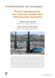
A maximum density line similar to the one shown in Figure 1 can be utilized as<br />
a guide to uniform grading. To make a chart with a maximum density line for your<br />
operation, use a FHWA 0.45 Power Gradation Chart as shown in Figure 1. Draw<br />
a straight line between the lower left corner of the chart <strong>and</strong> the percent point for<br />
your largest sieve size that retains material.
Experience dictates that mixes with<br />
gradations that fall directly on the<br />
maximum density line should not be<br />
produced. Often there is insuffi cient<br />
room in the mixture for the liquid<br />
asphalt, <strong>and</strong> a plastic type material<br />
results. Another problem arises when<br />
the mix design is near the maximum<br />
density line. Gradation variations in<br />
stockpile material cause the curve<br />
to vary back <strong>and</strong> forth across the<br />
maximum density line, thereby gapgrading<br />
the mix. It is suggested that<br />
the mix designer select approximately<br />
two to four percentage points above<br />
the maximum density curve if he<br />
desires a fi ne texture. He should<br />
select two to four points below the<br />
curve if he desires a coarse texture,<br />
see Figure 2. These bowed up <strong>and</strong><br />
bowed down curves usually result in a<br />
good, forgiving mix.<br />
Rarely does a mix that lies on the<br />
maximum density line contain suffi cient<br />
voids in the mineral aggregate (VMA),<br />
especially if the design has a relatively<br />
high percentage of minus 200<br />
material. A grading selected on a line<br />
approximately parallel to the maximum<br />
density line will produce a uniformly<br />
graded mix that will be very forgiving.<br />
However, the maximum density line<br />
should be used only as a guideline for<br />
uniform grading. Other criteria such as<br />
VMA, stability <strong>and</strong> other specifi cations<br />
must also be met.<br />
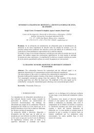
A mix design that makes an “S” across<br />
the maximum density line, as shown<br />
in Figure 3, can result in segregation<br />
problems.<br />
PERCENT PASSING<br />
100<br />
90<br />
80<br />
70<br />
60<br />
50<br />
40<br />
30<br />
20<br />
10<br />
0<br />
100 50 30 16 8 6 4 1/4 in 3/8 in 1/2 in 3/4 in 1 in 1 1/4 in 1 1/2 in<br />
200 80 40 20 10<br />
Horizontal scale represents sieve sizes raised to the .45 power<br />
MAXIMUM DENSITY LINE F1<br />
PERCENT PASSING<br />
100<br />
90<br />
80<br />
70<br />
60<br />
50<br />
40<br />
30<br />
20<br />
10<br />
0<br />
100 50 30 16 8 6 4 1/4 in 3/8 in 1/2 in 3/4 in 1 in 1 1/4 in 1 1/2 in<br />
200 80 40 20 10<br />
Horizontal scale represents sieve sizes raised to the .45 power<br />
SELECTING MIXES F2<br />
PERCENT PASSING<br />
100<br />
90<br />
80<br />
70<br />
60<br />
50<br />
40<br />
30<br />
20<br />
10<br />
0<br />
FINE<br />
TEXTURE<br />
FINE<br />
TEXTURE<br />
COARSE<br />
TEXTURE<br />
COARSE<br />
TEXTURE<br />
100 50 30 16 8 6 4 1/4 in 3/8 in 1/2 in 3/4 in 1 in 1 1/4 in 1 1/2 in<br />
200 80 40 20 10<br />
Horizontal scale represents sieve sizes raised to the .45 power<br />
"S" CURVES TEND TO SEGREGATE F3<br />
3
4<br />
PERCENT PASSING<br />
SLIGHTLY BOWED CURVES MAY DO WELL F4<br />
PERCENT PASSING<br />
100<br />
90<br />
80<br />
70<br />
60<br />
50<br />
40<br />
30<br />
20<br />
10<br />
0<br />
100<br />
90<br />
80<br />
70<br />
60<br />
50<br />
40<br />
30<br />
20<br />
10<br />
0<br />
100 50 30 16 8 6 4 1/4 in 3/8 in 1/2 in 3/4 in 1 in 1 1/4 in 1 1/2 in<br />
200 80 40 20 10<br />
Horizontal scale represents sieve sizes raised to the .45 power<br />
100 50 30 16 8 6 4 1/4 in 3/8 in 1/2 in 3/4 in 1 in 1 1/4 in 1 1/2 in<br />
200 80 40 20 10<br />
Horizontal scale represents sieve sizes raised to the .45 power<br />
SAME MIX 4 vs 7 POINTS F5<br />
LARGER PARTICLES<br />
ROLL TO THE OUTSIDE<br />
CURVE USING<br />
4POINTS<br />
CURVE USING<br />
7POINTS<br />
CONVEYOR<br />
<strong>SEGREGATION</strong> IN A PILE F6<br />
The slightly bowed curve shown<br />
in Figure 4 could result in good<br />
performance. But the potential benefi t<br />
that a designer tries to achieve by<br />
gap-grading is too often negated by<br />
segregation problems.<br />
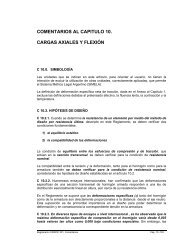
When plotting a mix gradation, plot<br />
as many sieve sizes as possible.<br />
Figure 5 illustrates how plotting<br />
to only a few points can result in a<br />
misleading graph. When only 4 sieve<br />
sizes are plotted as shown in Figure<br />
5 the curve may indicate a “forgiving”<br />
mix. But when seven sieve sizes are<br />
plotted, also shown in Figure 5, it is<br />
easy to see that the mix is actually<br />
gap-graded.<br />
STOCKPILING<br />
Proper stockpiling techniques are<br />
needed to insure that the material<br />
will be uniform when fed to the hot<br />
mix plant. Large stockpiles are very<br />
sensitive to single aggregate blends.<br />
Figure 6 shows a typical example of<br />
a single aggregate stockpile. In this<br />
example, segregation has occurred<br />
because a conveying system was<br />
used to form the stockpile. Large<br />
particles have rolled to the outside<br />
of the pile thereby segregating the<br />
material. Subsequently, segregated<br />
material is fed to the plant.
Generally, different-sized materials<br />
are stockpiled separately for feeding<br />
to an asphalt plant. This makes<br />
segregation less likely because the<br />
material is more evenly sized in<br />
each pile. However, segregation can<br />
occur in smaller aggregates if a wide<br />
variation in gradation exists. Stockpile<br />
techniques shown in Figures 7<br />
<strong>and</strong> 8 assure uniformity of material<br />
<strong>and</strong> signifi cantly reduce stockpile<br />
segregation. Dozer operation should<br />
be monitored to assure degradation is<br />
not occurring. Monitoring is especially<br />
critical when dealing with softer<br />
aggregates. NAPA Publication IS-69,<br />
Stockpiling <strong>and</strong> Cold Feed For Quality,<br />
gives good guidelines for proper<br />
stockpiling techniques.<br />
When sampling stockpile material<br />
to set up cold feed bin ratios, it is<br />
important to take several samples<br />
<strong>and</strong> use the median result as shown<br />
in Figure 9.<br />
ASPHALT FACILITIES<br />
Segregation can occur at numerous<br />
points in a hot mix asphalt plant.<br />
The location at which segregation is<br />
likely to occur in a plant depends on<br />
what type of facility it is. On a batch<br />
plant, the points of most concern are<br />
cold feed bins <strong>and</strong> hot bins. On drum<br />
mix plants, surge bins <strong>and</strong> storage<br />
bins are the points of most concern.<br />
DUMP AGGREGATES<br />
IN PILES NOT LARGER<br />
THAN A TRUCKLOAD<br />
MAKE PILES SO THEY STAY<br />
IN PLACE AND DO NOT ROLL<br />
DOWN SLOPES<br />
USE NUMEROUS SMALL PILES F7<br />
BUILD STOCKPILES IN LAYERS F8<br />
PERCENT PASSING ON CONTROL SIEVE<br />
BUILD PROGRESSIVE<br />
HORIZONTAL LAYERS<br />
BULLDOZER WITH CONVEYOR<br />
BULLDOZER WITH TRUCK<br />
BUILD PROGRESSIVE<br />
LAYERS ON SLOPE<br />
NOT GREATER<br />
THAN 3:1 SLOPE<br />
1 2 3 4 5 6<br />
SAMPLES TAKEN<br />
DO NOT DUMP<br />
DOWN SLOPE<br />
MEDIAN<br />
GRADATION<br />
(FOR COLD<br />
FEED BIN<br />
SETTING)<br />
STOCKPILE SAMPLING F9<br />
5
6<br />
TOP VIEW<br />
RECTANGULAR<br />
OPENING<br />
EFFECTIVE<br />
FEED AREA<br />
FEEDER BIN WITH RECTANGULAR OPENING F10<br />
TOP VEIW<br />
SELF-RELIEVING<br />
OPENING<br />
EFFECTIVE<br />
FEED AREA<br />
DEAD AREA<br />
CAUSED BY<br />
BRIDGING<br />
CLAM GATE<br />
SELF-RELIEVING FEEDER BIN F11<br />
FINE<br />
MATERIAL<br />
DUST SLIDES<br />
DOWN SIDE<br />
OF BIN<br />
HOT<br />
BIN<br />
SCREENS<br />
CLAM GATE<br />
COARSE<br />
MATERIAL<br />
BATCH<br />
TOWER<br />
HOT BIN <strong>SEGREGATION</strong> F12<br />
COLD FEED BINS<br />
Segregation in cold feed is usually<br />
not a problem unless the aggregate<br />
material consists of several sizes.<br />
Segregation should not occur when<br />
a single size of aggregate is placed<br />
in each feeder bin because there<br />
are no different sizes to segregate.<br />
However, if bridging of material<br />
occurs in the hopper, see Figure<br />
10, non-uniform feeding takes<br />
place, resulting in a segregated mix.<br />
By utilizing a self-relieving bottom<br />
shown in Figure 11, uniform feeding<br />
will occur all along the opening of the<br />
cold feed bin, eliminating bridging as a<br />
source of segregation.<br />
When working with a crusher-run<br />
aggregate, it can be benefi cial to use<br />
two cold feed bins to feed the same<br />
material. This practice tends to minimize<br />
wide variations by feeding smaller<br />
amounts of material from two bins,<br />
thus minimizing variations in gradation.<br />
HOT BINS ON A BATCH PLANT<br />
As mentioned, segregation can occur<br />
with all sizes of material. Segregation<br />
often occurs in the No. 1 hot bin due<br />
to the size <strong>and</strong> shape of the large bin<br />
<strong>and</strong> the wide size range of materials in<br />
that bin. The size variation in material<br />
in Bin 1 is potentially greater than any<br />
other part of the asphalt plant because<br />
its material size varies from as large<br />
as 3/16-inch all the way down to one<br />
micron.<br />
In recent years some have voiced<br />
concern about uniform dust return from<br />
baghouses to batch plants. Generally,<br />
material is uniformly collected in<br />
baghouses <strong>and</strong> is uniformly returned,<br />
but the material may actually be<br />
segregating in Bin 1. The ultra-fi ne<br />
material discharged from the bucket<br />
elevator may fall directly through the<br />
screen <strong>and</strong> lay on a sloping bin wall,<br />
Figure 12. It may lay there until the<br />
bin is about empty. Then a large slug<br />
of the dust may break loose <strong>and</strong> feed<br />
into the weigh hopper, producing an
ultra-fi ne batch that is segregated,<br />
<strong>and</strong> uncoated.<br />
In many cases non-uniform feed<br />
from the baghouse was incorrectly<br />
suspected to be the cause of<br />
segregation in the hot bin <strong>and</strong><br />
resulted in the addition of expensive<br />
<strong>and</strong> unnecessary equipment. There<br />
was simply an improper analysis<br />
of the problem. The proper solution<br />
should be to install a baffl e as shown<br />
in Figure 13. The baffl e causes the<br />
dust to slide to the center of the bin<br />
where it is uniformly mixed with the<br />
coarse materials.<br />
The same results can be achieved<br />
by using a baffl e to force the coarse<br />
material back to the sloping bin wall.<br />
There, it can be intermixed with<br />
the fi ne material. The method used<br />
depends on the head room <strong>and</strong> space<br />
available in the hot bins.<br />
Utilizing a dust blower at the<br />
baghouse <strong>and</strong> a cyclone type dust<br />
receiver properly located in Bin 1 has<br />
also proved effective in eliminating<br />
segregation in this area. However,<br />
many prefer to use baffl es because of<br />
relatively high maintenance costs for<br />
airlocks that h<strong>and</strong>le abrasive materials<br />
such as granite.<br />
DRUM MIXER<br />
BAFFLE<br />
MINIMIZES<br />
<strong>SEGREGATION</strong><br />
SCREENS<br />
HOT BIN WITH BAFFLE F13<br />
LIQUID<br />
ASPHALT<br />
EXHAUST<br />
MIX<br />
BATCH<br />
TOWER<br />
INCREASING MIXING TIME IN A DRUM MIXER F14<br />
Large particles will generally fl ow<br />
through a drum mixer at a slightly<br />
faster rate than small particles during initial start up <strong>and</strong> at plant shut down.<br />
Negative effects associated with this characteristic can be eliminated by adjusting<br />
the start/stop time intervals between the cold feed bins. Due to the continuous<br />
fl ow process that occurs after start-up, this characteristic does not produce<br />
segregation. The potential to segregate is also of little signifi cance unless the<br />
material is gap-graded.<br />
When gap-graded mixes are processed in a drum mixer, it becomes more<br />
diffi cult to achieve a thorough coating with a uniform thickness. The uncoated or<br />
thinly coated coarser materials are more likely to segregate. Such segregation<br />
can be reduced or eliminated through better coating. This can be accomplished<br />
by increasing the mixing time by extending the asphalt line farther up into the<br />
drum mixer as shown in Figure 14. For hard-to-coat materials, kick-back fl ights<br />
as shown in Figure 14 can be used, or a dam (donut) can be installed in the drum<br />
to increase the mixing time, Figure 15.<br />
HOT<br />
BIN<br />
VIRGIN<br />
BURNER<br />
7
8<br />
LIQUID<br />
ASPHALT<br />
EXHAUST<br />
MIX<br />
DRUM MIXER DAMS RETARD FLOW F15<br />
FINE<br />
COARSE<br />
DAMS<br />
BURNER<br />
DRUM DISCHARGE <strong>SEGREGATION</strong> F16<br />
DEFLECTOR<br />
PLATES TO<br />
STRAIGHTEN<br />
MATERIAL FLOW<br />
UNIFORM<br />
LOADING<br />
DRAG<br />
CONVEYOR<br />
COARSE<br />
AGGREGATE<br />
GRAVITY<br />
DISCHARGE<br />
BREACHING<br />
ANGULAR<br />
FLOW<br />
FINE<br />
AGGREGATE<br />
GRAVITY DISCHARGE F17<br />
An alternate method is to decrease<br />
the drum slope, which increases the<br />
dwell time <strong>and</strong> provides additional<br />
mixing. Increased dwell time, whether<br />
due to the addition of dams or due to<br />
decreasing the drum slope, increases<br />
the drum load. This may reduce the<br />
production rate if the drum drive motor<br />
is a limiting factor.<br />
An often overlooked factor which<br />
can signifi cantly affect coating quality<br />
<strong>and</strong> fi lm thickness is the amount of<br />
minus 200 material in the mix. Coating<br />
quality will be adversely affected if the<br />
amount of minus 200 material exceeds<br />
specifi cations or even if it is within<br />
specifi cations, but on the high side of<br />
the tolerance allowed. Because of the<br />
large amount of surface area present<br />
in fi ne material <strong>and</strong> because of its<br />
affi nity for the liquid asphalt, coarser<br />
material in the mix will have a reduced<br />
fi lm thickness even though it may<br />
appear to be fully coated. Reduced<br />
fi lm thickness makes the coarse<br />
material less sticky <strong>and</strong> increases its<br />
tendency to segregate. Reducing the<br />
amount of minus 200 material to the<br />
low side of the allowable tolerance<br />
will usually correct this problem.<br />
Moreover, it will be easier to produce<br />
a uniform mix <strong>and</strong> easier to h<strong>and</strong>le<br />
the mix throughout the trucking <strong>and</strong><br />
laydown operations.<br />
INTERNAL MOISTURE<br />
Retained internal moisture is rarely<br />
a problem while running RAP since<br />
the virgin aggregate containing the<br />
internal moisture is superheated<br />
above the mix termperature. The<br />
degree of superheat depends on the<br />
percent RAP, RAP moisture <strong>and</strong> the<br />
mix termperature. For example, with<br />
30% RAP containing 5% moisture, the<br />
virgin aggregate is heated to 512°F to<br />
produce 300°F mix. If retained internal<br />
moisture is a problem while producing<br />
a virgin mix, one of the aggregates,<br />
not containing internal moisture,<br />
can be added into the plant process
through the RAP system. This induces<br />
the plant to superheat the aggregate<br />
containing internal moisture, thus<br />
removing the internal moisture before<br />
the liquid AC is added. This helps<br />
coating <strong>and</strong> mimimizes AC absorption.<br />
An Alabama contractor reduced<br />
the moisture retained in a slag mix<br />
from 0.22% to .06% by adding 15%<br />
screenings through the RAP bin.<br />
DRAG CONVEYOR AT 90˚<br />
The coating of large stones can also<br />
be affected by internal moisture <strong>and</strong><br />
absorption. When internal moisture<br />
UNIFORM MIX<br />
is present in large aggregate its<br />
FIXED PLOW<br />
temperature tends to be cooler than<br />
fi ner material. Cooler stones will not DRUM DISCHARGE FLOW F18<br />
coat readily until they have given up<br />
their moisture <strong>and</strong> reached a uniform elevated temperature comparable to the<br />
temperature of the rest of the mixture. Internal moisture can be eliminated by<br />
increasing drying <strong>and</strong> mixing times using the methods described above.<br />
Asphalt absorption problems are related to internal moisture problems. This is<br />
because the same pores that contain the moisture in the stone will absorb a<br />
portion of the available asphalt. This absorption reduces the actual fi lm thickness<br />
on the outside surfaces. If absorption is suspected, break open several larger<br />
stones <strong>and</strong> examine them under a magnifying glass. A dark b<strong>and</strong> ranging from<br />
a few thous<strong>and</strong>s of an inch to 1/32-inch wide from the surface inward indicates<br />
that absorption is occurring. The solution to attaining the fi lm thickness originally<br />
desired is to increase the asphalt content to make up for the portion being<br />
absorbed.<br />
Mix discharged from drums by gravity is more sensitive than mix discharged<br />
from drums with a high lift where the material is required to make a 90 degree<br />
turn prior to discharge. With gravity discharge, coarse material often discharges<br />
on one side <strong>and</strong> fi ne material on the other. The segregated material drops directly<br />
onto a drag conveyor <strong>and</strong> continues to segregate right on through the batcher<br />
<strong>and</strong> bin as shown in Figure 16. The problem can be improved by restricting the<br />
discharge chute from the drum to a smaller opening, forcing the mix into the<br />
center of the drag conveyor. Adding defl ector plates or straightening vanes is also<br />
an effective way to make sure the drag conveyor is properly loaded from a gravity<br />
type discharge see Figure 17.<br />
Another solution is to install a plow or single discharge point in the drum as<br />
shown in Figure 18, forcing all mix to come out at one point. However, experience<br />
shows it is diffi cult to design <strong>and</strong> install an effective plow on most drum mixers.<br />
When possible it is best to set the drag conveyor at a 90 degree angle to the drum<br />
discharge to create a right angle change in material fl ow. This setting reduces or<br />
eliminates drum discharge segregation.<br />
9
COARSE MATERIAL<br />
GOES OVER THE TOP<br />
FINER MATERIAL<br />
BUILDS UP ALONG BOTTOM<br />
HYDROPLANING IN A DRAG CONVEYOR F19<br />
BIN LOADING BATCHER F20<br />
DISCHARGE CHUTE<br />
IS OFF-SET<br />
MATERIAL FLOW IS<br />
NOT STRAIGHT<br />
CHUTES THAT CAUSE UNSATISFACTORY MATERIAL FLOW F21<br />
10<br />
SURGE AND STORAGE BINS<br />
Drag Conveyors<br />
Segregation will usually not occur<br />
in a drag conveyor unless it is<br />
“hydroplaning.” Hydroplaning occurs<br />
as a result of a material buildup in<br />
the bottom of the drag conveyor. Cold<br />
conveyors that do not have fl oating<br />
hold-downs are prone to build-up on<br />
the bottom liners. The build-up creates<br />
a high friction drag surface that results<br />
in material spilling backwards over the<br />
drag fl ights as shown in Figure 19,<br />
even at very low production rates. This<br />
condition is easily observed. Material<br />
falls backwards down the drag<br />
conveyor instead of moving uniformly<br />
in one mass with full material from<br />
fl ight-to fl ight.<br />
When the drag conveyor is hydroplaning,<br />
considerable segregation can<br />
occur, especially at the beginning <strong>and</strong><br />
end of each run. Hydroplaning is more<br />
prevalent on batch plants where the<br />
segregation can be carried from batch<br />
to batch. Drag conveyors should be<br />
equipped with fl oating hold downs <strong>and</strong><br />
heated bottoms for cold start-ups.<br />
Segregation is minimized when the<br />
drag conveyor is as full as possible.<br />
When the slats are only partially fi lled,<br />
the larger aggregate is apt to roll to<br />
each side within the drag conveyor. So,<br />
it’s better to run at higher production<br />
rates to keep the drag conveyor full.<br />
When producing a segregation prone<br />
mix at production rates higher than<br />
the rate used by paving operations,<br />
store the extra mix <strong>and</strong> shut down<br />
production earlier than usual.<br />
Storage Bins<br />
The most sensitive area for segregation<br />
on a hot mix plant is in surge<br />
<strong>and</strong> storage bins. The large sizes of<br />
the bins contributes to segregation<br />
problems. Since the fi rst surge <strong>and</strong><br />
storage bins were developed many<br />
years ago, considerable improvement<br />
has been made on bin equipment to<br />
prevent segregation. Once of the most
detailed <strong>and</strong> complete studies of hot<br />
mix surge <strong>and</strong> storage segregation<br />
was conducted by the University of<br />
Texas in the early 70’s. From their<br />
investigation, various techniques were<br />
devised for eliminating segregation.<br />
The result of the study revealed that<br />
the bin loading batcher was a good<br />
device for eliminating segregation in<br />
surge <strong>and</strong> storage bins, Figure 20.<br />
The study also addressed various<br />
gate openings <strong>and</strong> showed that if the<br />
bin was properly loaded with uniform<br />
mix, the gate confi guration was not of<br />
signifi cant importance. However, the<br />
batcher is not an absolute “cure all”.<br />
It can create problems of its own <strong>and</strong><br />
it’s best to underst<strong>and</strong> how <strong>and</strong> why.<br />
Bin Loading Batchers<br />
CORRECT INCORRECT<br />
BATCHER CHARGING F22<br />
LARGE CHUTE OPENING SMALL CHUTE OPENING<br />
Perhaps the most popular device<br />
for eliminating segregation on surge<br />
or storage bins is the bin-loading<br />
batcher. The following observations<br />
<strong>and</strong> practices should be followed<br />
when using a batcher:<br />
a. The batcher should be fi lled to its<br />
maximum capacity (at least 5,000<br />
lbs.) And have a relatively large<br />
diameter gate opening to insure<br />
rapid discharge of material into the<br />
storage bin.<br />
b. The batcher must be loaded<br />
directly in the center <strong>and</strong> the material<br />
LESS <strong>SEGREGATION</strong> WITH SMALLER CHUTE OPENING F23<br />
from the chute loading the batcher should have no horizontal trajectory,<br />
Figure 21 <strong>and</strong> 22. Also, whenever mix is discharged through a chute, a<br />
small chute opening minimizes segregation, Figure 23. Remember, if the<br />
material segregates in the batcher, it will remain segregated throughout<br />
the bin.<br />
c. The batcher should be fi lled completely before each drop. Normally,<br />
two high bin indicators are utilized. One dumps the gates <strong>and</strong> the other<br />
insures the gates will dump if the fi rst indicator fails. When the batcher<br />
gates fail to open, mix backs up in the drag conveyor all the way into the<br />
drum. This possibility makes operators want to leave the gates open,<br />
totally defeating the batcher’s purpose. If at all possible, timers should not<br />
be used on batchers except to control the gate open-time. The production<br />
rate of the plants will vary, <strong>and</strong> different amounts of time should not be<br />
used on batchers except to control the gate open-time. The production<br />
rate of plants will vary, <strong>and</strong> different times are required to fi ll the batcher.<br />
Remember, it is essential that the batcher be fi lled each time so that an<br />
adequate slug or a single mass drops into the bin.<br />
11
BIN LEVEL AFFECTS<br />
DROP DISTANCE AND<br />
MOMENTUM OF<br />
DROPPED MATERIAL<br />
BIN CHARGING BATCHER F24<br />
COARSE<br />
BIN KEPT TOO FULL F25<br />
BATCHER RULES F26<br />
12<br />
FINE<br />
1. Batch size should be at least 5,000 lbs. (more is better).<br />
2. Batcher should be loaded in the center.<br />
3. Material should flow straight down into the batcher.<br />
(no horizontal trajectory).<br />
4. Batcher gate timers should be adjusted so that gates shut<br />
with 6-8 inches of material left in the batcher.<br />
Do not allow any free flow through the batcher.<br />
5. Batcher should be maintained so that the mix drops out<br />
rapidly as a slug.<br />
d. The batcher should never be<br />
completely emptied. The gate-opentime<br />
should be adjusted so that a small<br />
amount of material (approximately 6<br />
inches) remains in the batcher after<br />
the discharge cycle is completed. If<br />
the gate remains open too long, new<br />
material falls straight through the<br />
batcher <strong>and</strong> goes directly into the bin,<br />
resulting in r<strong>and</strong>om segregation.<br />
e. When utilizing a bin-loading batcher,<br />
the emptier the bin, the farther the fall of<br />
the material <strong>and</strong> the more likely a level,<br />
uniform bin-loading will occur, Figure<br />
24. The worst situation when operating<br />
a bin loading batcher is to have the bin<br />
material level consistently near the<br />
top, Figure 25. The mix drop then has<br />
insuffi cient momentum <strong>and</strong> results in<br />
peaks of material instead of splattering<br />
the material to form a level surface. The<br />
rules for correct batcher operation are<br />
summarized in Figure 26.<br />
Loadout From<br />
Surge or Storage Bins<br />
If the surge or storage bin is uniformly<br />
fi lled, loadout of hot mix asphalt from<br />
the bin is not of great concern. Pulling<br />
material below the cone is not as<br />
sensitive as with the old type centerloaded<br />
bins. This is due in part to<br />
improved bin loading with batchers<br />
<strong>and</strong> rotating chutes, but results<br />
primarily from utilizing a steep cone<br />
angle that produces a mass fl ow of<br />
material from the bin. With most nongap-graded<br />
materials, the bin can<br />
be emptied without any appreciable<br />
segregation. However, with gapgraded<br />
material the bin level should<br />
still not be allowed to drop below the<br />
cone. Also, constantly running with the<br />
cone empty will accelerate cone wear.<br />
Rapid discharge from the silo gate<br />
helps eliminate segregation in trucks.<br />
This reduces the chance of segregation<br />
in the truck bed by minimizing the<br />
rolling action of the mix as it is fl owing<br />
into the truck bed.
In cold weather, bins should be<br />
insulated, at least on the cone. Could<br />
surfaces can cause the mix to stick<br />
the cone <strong>and</strong> under these conditions<br />
the material can plug fl ow instead of<br />
discharging in a uniform mass fl ow.<br />
TRUCK LOADING AND UNLOADING<br />
Due to rapid truck loading underneath<br />
surge or storage bins, truck drivers<br />
often tend to pull the truck under the<br />
bin <strong>and</strong> not move it while loading. If the<br />
mix is sensitive to segregation, larger<br />
stones will roll to the front of the truck,<br />
to the rear, <strong>and</strong> to the side, resulting in<br />
the coarse material being the fi rst <strong>and</strong><br />
last material to be discharged from the<br />
truck bed. The coarse material on each<br />
side will then be trapped in the wings<br />
of the paver to be discharged between<br />
truck loads. This discharging results in<br />
coarse areas of pavement between<br />
each truck load. This type of loading is<br />
shown in Figure 27.<br />
By loading the truck in at least three<br />
different drops, with the fi rst drop being<br />
very near the front of the truck bed, the<br />
second drop extremely close to the tail<br />
gate, <strong>and</strong> the third drop in the center,<br />
segregation caused by incorrect truck<br />
loading is eliminated. This type of<br />
loading is shown in Figure 28.<br />
Bins equipped with weight batchers<br />
as shown in Figure 29 tend to batch<br />
material directly into the trucks in<br />
a manner similar to the bin loading<br />
batcher. The weigh batcher, if designed<br />
properly, greatly insures uniform<br />
loading of the truck <strong>and</strong> improves the<br />
chance of avoiding segregation with a<br />
sensitive mix.<br />
When unloading a truck into a paver<br />
hopper it is important to discharge the<br />
material as a mass instead of dribbling<br />
the material into a paver. To do this,<br />
the bottom of the truck bed needs to<br />
be in good condition <strong>and</strong> lubricated so<br />
that the entire load will slide rearward.<br />
To further assure that the material is<br />
discharged as a mass, elevate the<br />
truck bed to a large, but safe angle,<br />
Figure 30.<br />
SINGLE DROP<br />
IMPROPER TRUCK LOADING F27<br />
PROPER TRUCK LOADING F28<br />
WEIGH BATCHER<br />
THREE DIFFERENT DROPS<br />
1 3 2<br />
BIN WITH WEIGH BATCHER F29<br />
13
14<br />
ROADTEC<br />
MASS MOVEMENT<br />
LARGER DUMPING ANGLE ASSURES MASS DISCHARGE F30<br />
ENCLOSURE<br />
POCKET OF COARSE MIX<br />
COLLECTS BEHIND<br />
ENCLOSURE AS MIX<br />
SLIDES DOWN TRUCK BED<br />
Rapid truck discharge fl oods the<br />
paver hopper <strong>and</strong> minimizes materialrun-around<br />
that often occurs at the<br />
tail gate. Rapid discharge prevents an<br />
accumulation of coarse material at the<br />
outside portion of the paver wings.<br />
With sensitive mixes it is often<br />
necessary to modify the forward<br />
portion of the truck bed to eliminate<br />
undesirable effects caused by the<br />
hydraulic cylinder enclosure. If the<br />
mix has a tendency to segregate,<br />
a pocket of coarse mix can occur<br />
as the mix slides away from the<br />
cylinder enclosure. As the load moves<br />
rearward, the mix caves in forcing<br />
large stones to accumulate in the<br />
center of the bed at the front of the<br />
truck. Then as the load moves into the<br />
paver, “end of the load” segregation<br />
occurs, Figure 31. Adding a plywood<br />
or light gauge metal cover across the<br />
entire front of the bed from side-toside<br />
will mimimize this problem.<br />
CYLINDER ENCLOSURE CAUSES "END OF LOAD" <strong>SEGREGATION</strong> F31<br />
PAVER<br />
Even though material has been<br />
successfully processed through the<br />
cold feed bin, through the plant,<br />
through the surge or storage bin,<br />
then uniformly loaded on the truck,<br />
segregation can still occur in the paver.<br />
Improper operation of a paver can<br />
cause segregation in varying degrees.<br />
Here are suggestions that should be<br />
considered when segregation occurs<br />
at the paver.<br />
a. Do not completely empty the hopper between each truck load. Coarse material<br />
tends to roll to each side of the truck bed <strong>and</strong> thus roll directly into the wings of<br />
the hopper. By leaving material in the hopper the coarse material has a better<br />
chance of being mixed with fi ner material before being placed on the road.<br />
b. Dump hopper wings only as required to level the material load in the hopper.<br />
Dumping eliminates the valleys in the material bed, thereby minimizing rolling<br />
that occurs when unloading. It allows the truck tailgate to swing open fully to fl ood<br />
the hopper with mix, Figure 32.
c. Dump the truck so as to fl ood<br />
the hopper. With the hopper as full<br />
as possible, material tends to be<br />
conveyed out from under the truck <strong>and</strong><br />
minimizes the tendency to roll as it is<br />
dumped into the hopper.<br />
d. Open hopper gates as wide as<br />
possible to insure that the augers are<br />
full. By closing the gates <strong>and</strong> starving<br />
the augers for mix, fi ne material will<br />
drop directly on the ground causing<br />
coarse material to be augured to each<br />
side, Figure 33.<br />
e. Run the paver as continuously<br />
as possible. Start <strong>and</strong> stop only as<br />
necessary. Adjust the paver speed to<br />
balance paver production with plant<br />
production.<br />
e. Run the paver as continuously<br />
as possible. Start <strong>and</strong> stop only as<br />
necessary. Adjust the paver speed to<br />
balance paver production with plant<br />
production.<br />
f. Run augers continuously. Auger<br />
speed should be adjusted so that<br />
a continuous, slow fl ow of material<br />
occurs. Augers that run at high speeds<br />
are cycling on <strong>and</strong> off continuously <strong>and</strong><br />
contribute signifi cantly to segregation<br />
at the paver.<br />
g. If augers are running too fast, the<br />
center of the mat will be defi cient of<br />
material <strong>and</strong> this will generally result<br />
in a coarse strip, Figure 34.<br />
HOPPER<br />
WING<br />
HOPPER<br />
WING<br />
PAVER HOPPER WINGS F32<br />
HOPPER<br />
GATE<br />
SEGREGATED MIX<br />
DRIVE<br />
SPACE BETWEEN<br />
CONVEYORS<br />
HOPPER<br />
GATE<br />
PAVER HOPPER GATES F33<br />
CONVENTIONAL PAVER DESIGN F34<br />
15
UNSEGREGATED MIX<br />
SPACE BETWEEN<br />
CONVEYORS<br />
CONVENTIONAL PAVER DESIGN WITH BAFFLES F35<br />
UNSEGREGATED MIX<br />
BAFFLE PLATES<br />
DRIVE<br />
DRAG CHAIN HEAD SPROCKETS<br />
ARE CLOSER TO AUGER<br />
DRIVE<br />
REDUCED SPACE<br />
BETWEEN CONVEYORS<br />
ROADTEC PAVER DESIGN F36<br />
SHUTTLE BUGGY MATERIAL TRANSFER VEHICLE BY GRAVITY AUGER F37<br />
16<br />
Baffl e plates, as shown in Figure 35,<br />
will also prevent coarse materials from<br />
rolling in front of the auger gear box<br />
<strong>and</strong> causing center line segregation.<br />
With the installation of the baffl es, the<br />
augers then divert material uniformly<br />
to the center. Figure 34 shows a<br />
conventional design where space<br />
between conveyors causes center<br />
line segregation. Figure 36 shows the<br />
Roadtec design with two important<br />
changes made on newer Roadtec<br />
pavers to minimize segregation <strong>and</strong><br />
eliminate the need for baffl es:<br />
1. Flight chains now have less space<br />
between them at the center of the<br />
hopper.<br />
2. Head sprockets of the fl ight chains<br />
are now closer to the auger.<br />
Another Roadtec Paver design feature<br />
which further reduces segregation<br />
is a gravity fed auger. Instead of the<br />
paver auger being fed by drag chains<br />
pulling hot mix from the bottom of the<br />
paver hopper, the hot mix in the paver<br />
hopper mass fl ows directly into the<br />
paver auger by gravity <strong>and</strong> is metered<br />
by hydradraulically activated clam<br />
gates. Paver maintenance is also<br />
reduced due to elimination of the drag<br />
chains, Figure 37.<br />
h. If the outer edges of the paver<br />
auger are defi cient of material, coarse<br />
strips along the outsides can occur<br />
as the coarse aggregate rolls to the<br />
outsides.<br />
i. If possible, adjust paver extensions<br />
so that the paver pulls the same<br />
amount of material from each side<br />
of the hopper. If one side is pulling<br />
more material, a valley will form in<br />
that side of the paver hopper, causing<br />
segregation to occur in sensitive<br />
mixes. If correction cannot be made<br />
by adjusting the extension, offset<br />
the truck slightly towards the side<br />
requiring more material to even out<br />
the material bed in the hopper.
j. Pavers without auger extensions<br />
can cause outside edge segregation. A<br />
segregation prone mix can segregate<br />
without auger extensions as the mix<br />
piles up at the end of the auger <strong>and</strong><br />
the larger aggregate rolls off toward the<br />
outside edge of the road.<br />
SHUTTLE BUGGY ®<br />
MATERIAL TRANSFER VEHICLE<br />
The diffi culty of dumping mix from the<br />
truck into the paver while deepening the<br />
paver moving continuously should be<br />
apparent from our earlier discussion.<br />
Figure 38 shows a Shuttle Buggy<br />
material transfer vehicle that allows<br />
the truck to stop at a suitable distance<br />
ahead of the paver, then dump its entire<br />
load without moving. The shuttle Buggy<br />
carries 30 to 35 tons of mix.<br />
The drag conveyor on the front of the<br />
Shuttle Buggy is suffi ciently wide to<br />
accept the full width of the mix load<br />
from the truck (uninterrupted) <strong>and</strong><br />
convey it up <strong>and</strong> into the holding hopper<br />
of the Shuttle Buggy. Two variable pitch<br />
augers in the bottom of the holding<br />
hopper re-mix the material as it<br />
moves into the rear swivel discharge<br />
conveyor.<br />
A holding hopper is installed on<br />
the paver, allowing storage of<br />
approximately 20 tons of material. The<br />
swivel conveyor from the Shuttle Buggy<br />
fi lls the hopper from the top. Figure 39<br />
shows loading from an adjacent line.<br />
This new concept allows continuous<br />
operation of the paver, re-blends the<br />
material <strong>and</strong> allows the use of large,<br />
long trailers.<br />
Moreover, the holding hopper on the<br />
paver eliminates the accumulation<br />
of coarse material in the wings.<br />
Accumulation of coarse material <strong>and</strong><br />
dumping of the wings is a major cause<br />
of end-of-the-load segregation.<br />
SHUTTLE BUGGY MATERIAL TRANSFER VEHICLE F38<br />
PAVER<br />
STRING LINE<br />
STRING LINE<br />
SHUTTLE BUGGY TRUCK<br />
SHUTTLE BUGGY OPERATING IN ADJACENT LANE F39<br />
SHUTTLE BUGGY MIXING AUGERS F40<br />
17
18<br />
These units have proven to completely eliminate end-of-load <strong>and</strong> r<strong>and</strong>om<br />
segregation due to three-blending of material by the mixing augers, Figure 40. The<br />
resulting pavement smoothness exceeds anything pre-viously accomplished on a<br />
consistent basis.<br />
DIAGNOSTIC SYSTEM<br />
The Segregation Diagnostic Chart accompanying this technical paper shows fi ve<br />
different kinds of segregation. It provides a diagnostic system for analyzing the<br />
potential causes of segregation based on these types of segregation as they<br />
occur on the road. This, the most likely causes of segregation can be quickly<br />
identifi ed in the chart. Then this paper can be consul ted for more detailed<br />
information regarding causes <strong>and</strong> remedies.<br />
TESTING<br />
Segregation <strong>and</strong> asphalt content go h<strong>and</strong>-in-h<strong>and</strong>. If mix uniformly produced<br />
<strong>and</strong> uniformly produced <strong>and</strong> uniformly coated <strong>and</strong> the material segregates<br />
after mixing, a sample of coarse material will reveal low asphalt content while a<br />
sample of fi ne material will show high asphalt content. NAPA Publication QIP109<br />
shows methods of analyzing asphalt content <strong>and</strong> extraction problems. Refer to<br />
this publication if segregation is occurring in the sampling or in the splitting of the<br />
material prior to running extraction tests.<br />
In summation, segregation in hot mix bituminous mixtures is a common <strong>and</strong><br />
persistent problem. However, the problem can be controlled <strong>and</strong> even eliminated<br />
through proper mix design <strong>and</strong> through proper maintenance <strong>and</strong> operation of<br />
plants, trucks, <strong>and</strong> paving equipment. It is hoped this paper will assist in analyzing<br />
the problems <strong>and</strong> will be helpful in the selection of an effective cure.
NOTES<br />
19
20<br />
NOTES
a subsidiary of Astec Industries, Inc.<br />
PO BOX 72787 • 4101 JEROME AVE. • CHATTANOOGA, TN 37407 U.S.A. • 423-867-4210 • FAX 423-867-4636 • www.astecinc.com<br />
© ASTEC 2003 1M WMS 11/03 Printed in USA.