dmrb volume 6 section 3 part 5 - td 51/03 - Department for Transport
dmrb volume 6 section 3 part 5 - td 51/03 - Department for Transport
dmrb volume 6 section 3 part 5 - td 51/03 - Department for Transport

You also want an ePaper? Increase the reach of your titles
YUMPU automatically turns print PDFs into web optimized ePapers that Google loves.
Chapter 2<br />
Segregated Left Turn Lanes<br />
2.33 Where a physical island is to be provided, a<br />
plain lit bollard shall be installed at the start of the<br />
island. A minimum clearance of 0.6m between the<br />
edge of the sign or bollard and edge of the physical<br />
island shall be provided. Road markings shall be<br />
provided in accordance with paragraph 2.44 of this<br />
standard.<br />
2.34 The presence of pedestrian, cyclist and/or<br />
equestrian crossings shall be signed in accordance<br />
with Chapter 4 of the Traffic Signs Manual,<br />
Warning Signs. The signs to be used shall be<br />
TSRGD Diag 543 <strong>for</strong> a signal-controlled crossing,<br />
TSRGD Diag 544 <strong>for</strong> a zebra crossing, TSRGD<br />
Diag 950 <strong>for</strong> a cycle route and TSRGD Diag<br />
550.1 <strong>for</strong> equestrians.<br />
Approach Layout<br />
2.35 The approach arrangements can consist of either<br />
a dedicated lane or diverge on approach.<br />
2.36 Dedicated lanes on approach, see Fig 2/6,<br />
provide the highest capacity entry to a segregated left<br />
turn lane. They require careful design of signing and<br />
road markings such as the use of signs to Diag 2019<br />
and road markings to Diag 1<strong>03</strong>8 on the approach, to<br />
avoid driver confusion that may result in lane changing<br />
manoeuvres occurring adjacent to the segregated left<br />
turn lane entry.<br />
2.37 Diverge layouts, as shown on Fig 2/7, are a<br />
means of starting a segregated left turn lane, either as<br />
an enhancement to an existing layout or where the<br />
approach road is single carriageway as shown on<br />
Fig 2/8.<br />
2.38 Dedicated lanes on approach can create<br />
difficulties <strong>for</strong> cyclists and should only be used if either<br />
few cycle movements are expected, or cycle movements<br />
are provided <strong>for</strong> off the carriageway. Diverge layouts<br />
are more cycle friendly than dedicated lanes.<br />
2.39 The entry arrangements consist of an approach<br />
taper, if required, and an entry in accordance with<br />
Table 2/4 and as shown on Figs 2/6 to 2/8.<br />
2.40 The approach taper will be dependent on site<br />
constraints and the use of the minimum taper values<br />
contained in Table 2/3 is recommended.<br />
2/6<br />
Volume 6 Section 3<br />
Part 5 TD <strong>51</strong>/<strong>03</strong><br />
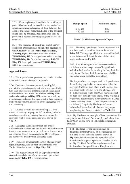
Design Speed Minimum Taper<br />
≤ 60 kph 1:10<br />
> 60 kph 1:15<br />
Table 2/3: Minimum Approach Tapers<br />
2.41 The entry taper length <strong>for</strong> the segregated left<br />
turn lane shall be provided in accordance with<br />
Table 2/5. The segregated left turn lane width shall<br />
be a minimum of 3.5m at the start of the entry<br />
taper, as shown on Fig 2/6.<br />
2.42 Any widening required to accommodate a<br />
cycle lane and the swept paths of Large Goods<br />
Vehicles shall be developed along the length of the<br />
entry taper. The length of the entry taper shall be<br />
calculated using the following method:<br />
The length of the entry taper shall be dependent on<br />
the widening required to accommodate either the<br />
segregated left turn lane island width, subject to a<br />
minimum width of 1.0m <strong>for</strong> a non-physical and<br />
2.1m (1.5m island width plus 0.3m marking offset<br />
on each side) <strong>for</strong> a physical island, or the widening<br />
required to accommodate the swept path of a Large<br />
Goods Vehicle (Table 2/2) and the provision of a<br />
cycle lane (if required). The larger of the two<br />
values shall be used to calculate the entry taper<br />
length using the factors contained in Table 2/5.<br />
2.43 Fig 2/9 shows an example of how to calculate the<br />
entry taper length <strong>for</strong> a 1.5m wide physical island less<br />
than 50m in length, <strong>for</strong> a 70 kph single carriageway<br />
approach.<br />
2.44 The taper <strong>for</strong> the hatching shall be<br />
developed asymmetrically on the segregated left<br />
turn lane side of the entry taper as shown on<br />
Fig 2/9 and shall terminate in a position offset<br />
0.3m from the edge of a physical island as shown<br />
on Fig 2/2. The 0.3m offset may be reduced to<br />
0.15m where the speed limit is 40mph or less.<br />
November 20<strong>03</strong>