dmrb volume 6 section 3 part 5 - td 51/03 - Department for Transport
dmrb volume 6 section 3 part 5 - td 51/03 - Department for Transport
dmrb volume 6 section 3 part 5 - td 51/03 - Department for Transport

You also want an ePaper? Increase the reach of your titles
YUMPU automatically turns print PDFs into web optimized ePapers that Google loves.
Chapter 3<br />
Subsidiary Deflection Islands<br />
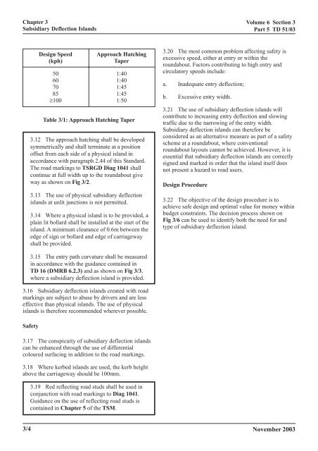
Design Speed Approach Hatching<br />
(kph) Taper<br />
50 1:40<br />
60 1:40<br />
70 1:45<br />
85 1:45<br />
≥100 1:50<br />
Table 3/1: Approach Hatching Taper<br />
3.12 The approach hatching shall be developed<br />
symmetrically and shall terminate at a position<br />
offset from each side of a physical island in<br />
accordance with paragraph 2.44 of this Standard.<br />
The road markings to TSRGD Diag 1041 shall<br />
continue at full width up to the roundabout give<br />
way as shown on Fig 3/2.<br />
3.13 The use of physical subsidiary deflection<br />
islands at unlit junctions is not permitted.<br />
3.14 Where a physical island is to be provided, a<br />
plain lit bollard shall be installed at the start of the<br />
island. A minimum clearance of 0.6m between the<br />
edge of sign or bollard and edge of carriageway<br />
shall be provided.<br />
3.15 The entry path curvature shall be measured<br />
in accordance with the guidance contained in<br />
TD 16 (DMRB 6.2.3) and as shown on Fig 3/3,<br />
where a subsidiary deflection island is provided.<br />
3.16 Subsidiary deflection islands created with road<br />
markings are subject to abuse by drivers and are less<br />
effective than physical islands. The use of physical<br />
islands is there<strong>for</strong>e recommended wherever possible.<br />
Safety<br />
3.17 The conspicuity of subsidiary deflection islands<br />
can be enhanced through the use of differential<br />
coloured surfacing in addition to the road markings.<br />
3.18 Where kerbed islands are used, the kerb height<br />
above the carriageway should be 100mm.<br />
3/4<br />
3.19 Red reflecting road studs shall be used in<br />
conjunction with road markings to Diag 1041.<br />
Guidance on the use of reflecting road studs is<br />
contained in Chapter 5 of the TSM.<br />
Volume 6 Section 3<br />
Part 5 TD <strong>51</strong>/<strong>03</strong><br />
3.20 The most common problem affecting safety is<br />
excessive speed, either at entry or within the<br />
roundabout. Factors contributing to high entry and<br />
circulatory speeds include:<br />
a. Inadequate entry deflection;<br />
b. Excessive entry width.<br />
3.21 The use of subsidiary deflection islands will<br />
contribute to increasing entry deflection and slowing<br />
traffic due to the narrowing of the entry width.<br />
Subsidiary deflection islands can there<strong>for</strong>e be<br />
considered as an alternative measure as <strong>part</strong> of a safety<br />
scheme at a roundabout, where conventional<br />
roundabout layouts cannot be achieved. However, it is<br />
essential that subsidiary deflection islands are correctly<br />
signed and marked in order that the island itself does<br />
not present a hazard to road users.<br />
Design Procedure<br />
3.22 The objective of the design procedure is to<br />
achieve safe design and optimal value <strong>for</strong> money within<br />
budget constraints. The decision process shown on<br />
Fig 3/6 can be used to identify both the need <strong>for</strong> and<br />
type of subsidiary deflection island.<br />
November 20<strong>03</strong>