Bugle PDF Tutorial
Bugle PDF Tutorial
Bugle PDF Tutorial

Create successful ePaper yourself
Turn your PDF publications into a flip-book with our unique Google optimized e-Paper software.
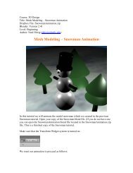
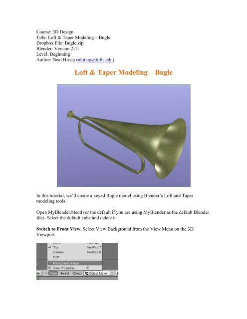
Course: 3D Design<br />
Title: Loft & Taper Modeling – <strong>Bugle</strong><br />
Dropbox File: <strong>Bugle</strong>.zip<br />
Blender: Version 2.41<br />
Level: Beginning<br />
Author: Neal Hirsig (nhirsig@tufts.edu)<br />
Loft & Taper Modeling – <strong>Bugle</strong><br />
In this tutorial, we’ll create a keyed <strong>Bugle</strong> model using Blender’s Loft and Taper<br />
modeling tools.<br />
Open MyBlender.blend (or the default if you are using MyBlender as the default Blender<br />
file). Select the default cube and delete it.<br />
Switch to Front View. Select View Background from the View Menu on the 3D<br />
Viewport.
Press the Use Background Image button and press the small icon to the right of the word<br />
“Image”. Select the <strong>Bugle</strong>.jpg file. This file is located in the <strong>Bugle</strong>.zip file. The<br />
background image is displayed in the scene<br />
In the Background Image Panel set the Blend (Transparency) to .65 and the Size to 7.<br />
Place your cursor in the center of the display. Press Space / Add / Curve / Bezier Curve.
This places a Bezier curve on the stage. Zoom in a bit. Notice that the Bezier curve has 2<br />
vertices. Each vertex has a control handle with 2 moveable endpoints. Unfortunately,<br />
Blender does not display a distinct visual difference between the vertices and the control<br />
handle end. It is sometimes very difficult to distinguish between the two. When Blender<br />
first creates the circle the handles are in “AUTO” mode; that is a special mode to ensure<br />
they are properly placed. Press the VKEY. This sets the handles to either VECTOR<br />
(straight line).<br />
We will use Blender’s Loft tool to make the non-fluted portions of the bugle (everything<br />
except the mouthpiece and the fluted horn). Press the GKEY (Grab) and place the default<br />
Bezier curve so that the first vertex is at the end of the mouthpiece as shown below (Note<br />
the first “dot is not a vertex, it is the first vertex’s left handle endpoint).<br />
Press the AKEY to deselect the vertices.<br />
Select the right vertex (not the right handle) and using the Blue Transform Arrow move it<br />
down a bit to follow the centerline of the bugle image.
Hold the CTRL Key Down and LMB click farther down the <strong>Bugle</strong> tube as shown. A new<br />
vertex is created (with handles) which is connected to the last.<br />
Keep the CTRL KEY press and continue to add vertices to the Bezier curve following the<br />
centerline of the bugle tube. You may have to place the vertices closer as you go around<br />
the curves of the tube. Stop when you reach the top of the tube as shown below. (Note:<br />
you can press the UKEY to undo any vertices you have made).<br />
You can now zoom in and go back selecting any vertices or handles to smooth out the<br />
curve as much as possible. (Select and press the GKEY).
Save your file F2. Our Bezier curve is currently 2-dimensional. We need to make it 3dimensional<br />
as the upper part of the bugle is on a plane different than the lower part of<br />
the bugle. In the Curves and Surfaces Panel press the 3D button.<br />
This allows us to move some of the vertices in 3 dimensions. It also adds some hatching<br />
to the curve.<br />
Turn off the 3D Widget.<br />
The bugle curve begins to bend away from us in the middle of the first curve. Select all of<br />
the vertices from the middle of the first curve to the end as shown below.
Place your 3D cursor in the center of the first curve (the start of the selected vertices) as<br />
shown.<br />
Change the Rotation/Scale Pivot point to 3D cursor.
Switch to Top View. Press the RKEY (Rotation) and rotate the vertices out a bit as<br />
shown below.<br />
If you rotate your view the vertices look like below.<br />
Switch back to Front View. The first curve is probably out of position.
Move the vertices back into position.<br />
Adjust the other curve vertices as well.
Switch to Front View. Zoom out and place your 3D cursor in the center of the display.<br />
Turn on the 3D widget and set the Rotation/Scale pivot point back to Meridian.
TAB out of Edit Mode.<br />
Press Space / Add / Curve / Bezier Circle.<br />
TAB out of Edit Mode. In the Transform Properties Panel name this object Loft Shape.<br />
Set the SIZE X and SIZE Y to .1
Select the Bezier Curve only. In the BEVOB box type Loft Shape and press ENTER.<br />
This lofts the Bezier circle along the Bezier curve forming the turned tube part of the<br />
bugle.
In the Transform Properties Panel name this object <strong>Bugle</strong> Tube.<br />
Save your file CTRL-W. Switch to Front View. We will now build the top fluted horn<br />
part of the bugle using Blender’s Taper tool. Blender’s Taper tool is a fun tool to<br />
experiment with as many different (and unexpected) shapes can be constructed. However<br />
it is cumbersome to use with any precision. To create the top fluted horn part of our bugle<br />
we will need 3 Bezier objects; a Bezier curve to use as a lofting path, a Bezier curve to<br />
use as a taper path and a Bezier circle to use as the shape to loft and taper.<br />
In front view place your 3D cursor in the center of the display and press Space / Add /<br />
Curve / Bezier curve. Once displayed, press the VKEY to make it a straight line. Select<br />
both vertices (AKEY if needed) and move it to the end of the <strong>Bugle</strong> Tube object as<br />
shown.
Select the right vertex. Use the Red Transform Widget Arrow to move it to the right (at<br />
the point where the fluting increases dramatically) as shown.<br />
Turn off the Transform Widget. With the right vertex still selected, hold down the CTRL<br />
key and LMB click a new vertex at the end of the bugle image as shown.<br />
Note: This Bezier curve now has 3 vertices; one at the left, one at the point of the flute<br />
increase and one at the end. TAB out of Edit Mode. In the Transform Properties Panel<br />
name this curve Loft Path.
Place your 3D cursor in the middle of the display and press Space / Add / Curve / Bezier<br />
Curve. When displayed, press the VKEY to make it a straight line. Select both vertices<br />
(AKEY if needed) and move it to the top of the <strong>Bugle</strong> Tube image as shown.<br />
Select the right vertex. Move it to the right (at the point where the fluting increases<br />
dramatically) as shown.<br />
With the right vertex still selected, hold down the CTRL key and LMB click a new vertex<br />
at the end of the bugle flute as shown.
Note: This Bezier curve now has 3 vertices; one at the left, one at the point of the flute<br />
increase and one at the end. TAB out of Edit Mode. In the Transform Properties Panel<br />
name this curve Taper Path.<br />
Place your 3D cursor in the middle of the display and press Space / Add / Curve / Bezier<br />
Circle. TAB out of Edit Mode. In the Transform Properties Panel name this object Shape<br />
and set the SIZE X and SIZE Y to .4 (this is 4 times the size of the shape we initially used<br />
for the bugle tube object)<br />
Select the Loft Path Object. In the Curves and Surfaces Panel, type in Shape for the<br />
BEVOB and Taper Path for the TAPEROB.<br />
This lofts the Shape object along the Loft Path and uses the Taper Path to control its taper<br />
amount.
Press the ZKEY to go back to Wireframe Mode. Turn on the Transform Widget. Select<br />
the Taper Path object. TAB into Edit Mode. Select the middle vertex (at the point of the<br />
flute increase – make sure it is the vertex and not the handle).<br />
Use the Blue Transform Widget Arrow to move the vertex up until the size of the taper is<br />
about the size shown in the background image as shown below.
Select the left vertex alone (make sure it is the vertex and not the handle). Use the Blue<br />
Transform Widget Arrow to move the vertex down until the size of the taper is about the<br />
size shown in the background image as shown below.<br />
Select the middle vertex alone (make sure it is the vertex and not the handle). Use the<br />
Blue Transform Widget Arrow to move the vertex up to re-adjust the size of the taper as<br />
shown below.
Select the right vertex alone (make sure it is the vertex and not the handle). It is a bit hard<br />
to find. Below is a close-up view of the end vertex selected.<br />
Use the Blue Transform Widget Arrow to move the vertex up until the size of the taper is<br />
about the size shown in the background image as shown below.
TAB out of Edit Mode. Select the Loft Path object. Move it in front view to overlap the<br />
bugle tube object a bit as shown.<br />
Switch to Top View. Zoom out a bit. Notice that the Loft Path object is not in the correct<br />
plane.
Use the Green Transform Widget Arrow to position it properly as shown.<br />
Press the ZKEY to enter shaded mode. Zoom out and rotate the view to see the bugle.
Re-name this object Flute.<br />
Save your file CTRL-W. Next we will model the mouth piece. We will create this from<br />
a mesh tube. Switch to Side View. Place your 3D cursor to the side of the bugle and press<br />
Space / Add / Mesh / Tube. Choose 24 vertices.
Switch to front view. TAB out of Edit Mode. Grab the tube and move it to the left side<br />
of the mouthpiece.<br />
Zoom in a bit. Switch to Wireframe Mode. TAB back into Edit Mode. (All of the<br />
Vertices should be selected) Press the SKEY and scale the vertices down to about the size
of the mouthpiece. Grab the tube and place it on the mouthpiece image. We will use the<br />
mouthpiece image as a general guide.<br />
Press the AKEY to deselect the vertices. Box Select the right vertices and move them to<br />
the left a bit as shown.<br />
Scale them up a bit.
Extrude the edges a bit. Extrude edges again<br />
Then scale down. Then extrude out<br />
Extrude and scale down. Then extrude.
Extrude and Scale.<br />
TAB out of Edit Mode and name this object Mouthpiece.<br />
In the Mesh panel press the Center New button. Grab and rotate the mouthpiece into the<br />
proper position at the front of the bugle.<br />
Switch to Top View and use the Green Transform Widget Arrow to position the<br />
Mouthpiece object.
ZKEY to shaded Mode and rotate the view. Our bugle has 3 objects (Mouthpiece, <strong>Bugle</strong><br />
Tube and Flute).<br />
Save your file CTRL-W. Select the Mouthpiece object alone. Press ALT-C and convert<br />
it to a Mesh object. Select the <strong>Bugle</strong> Tube object alone. Press ALT-C and convert it to a<br />
Mesh object. Select the Flute object alone. Press ALT-C and convert it to a Mesh object.<br />
Now that the 3 elements are mesh objects we can further refine their shape. Zoom in on<br />
the connection point between the Flute and the <strong>Bugle</strong> Tube objects. By adjusting the size<br />
or position or rotation of the end vertices of these two objects, smooth out the connection<br />
point as shown.
Zoom in on the connection point between the Mouthpiece and the <strong>Bugle</strong> Tube objects.<br />
Smooth out this connection as well.<br />
Select the Mouthpiece, <strong>Bugle</strong> Tube and Flute objects together. Press CTRL-J (Join) and<br />
join them into one mesh.<br />
In the Modifier Panel press the Add New button and select the SbSurf Modifier from the<br />
dropdown list.
In the SubSurf controls set the Levels to 2 and the Render Levels to 2.<br />
. In the Link and Materials Panel press the Set Smooth button.<br />
In the Transform Properties Panel name this object <strong>Bugle</strong><br />
Select the Loft Shape object from and delete it. Select the Shape object and delete it.<br />
Select the Taper Path object and delete it.<br />
Press View Background and press the view background image button removing it from<br />
the display.<br />
Save your file CTRL-W.
Add Layer 10 to the scene (This layer contains the camera and camera focus objects)<br />
Change the lower right Perspective view to camera view. Adjust the location of the<br />
camera focus and the camera focus objects to create a view similar to the one below in<br />
camera view.<br />
Select the <strong>Bugle</strong> object and press F5 (Shading). In the Material Panel press the Add New<br />
button. In the Texture Panel press Add New. Press F6 (Textures). In the Texture Panel<br />
use the Type dropdown box to select Image.<br />
In the Image Panel press the Load Image button. Select the goldalum.jpg image file. This<br />
file is located in the <strong>Bugle</strong>.zip file. In the Image Panel set the X and Y repeat to 4.
Press F10 (Scene). Add Layer 20 to the scene (This layer contains the lighting set-up)<br />
Render F12.<br />
You can save your rendering as an image file by pressing F3. Select the directory you<br />
want the image saved and name the file (you must add the .jpg file extension). Press Save<br />
JPEG when finished.<br />
A finished copy of this tutorial file named <strong>Bugle</strong>Complete.blend is located in the<br />
<strong>Bugle</strong>.zip file.