
You also want an ePaper? Increase the reach of your titles
YUMPU automatically turns print PDFs into web optimized ePapers that Google loves.
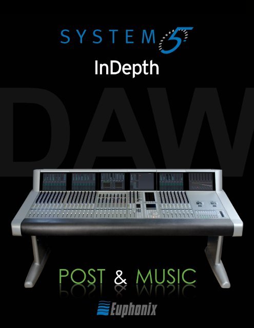
<strong>System</strong> 5 Digital Audio Mixing <strong>System</strong> - <strong>InDepth</strong><br />
1
EUPHONIX - SYSTEM 5 INDEPTH<br />
Table of Contents<br />
<strong>System</strong> 5 ........................................................................................................................... 4<br />
<strong>System</strong> 5 Key Features .................................................................................................... 4<br />
Innovative Solutions ........................................................................................................ 4<br />
<strong>System</strong> Components ....................................................................................................... 5<br />
The Control Modules ....................................................................................................... 6<br />
Typical Equipment Rack ................................................................................................. 6<br />
<strong>System</strong> 5 Control Surface - 6 Module Frame ............................................................... 7<br />
Channels .......................................................................................................................... 8<br />
Strips .................................................................................................................................. 9<br />
Inputs .............................................................................................................................. 11<br />
Channel Process Order ................................................................................................ 12<br />
EQ & Filters ..................................................................................................................... 12<br />
Dynamics ....................................................................................................................... 13<br />
Bus Routing and Aux Sends .......................................................................................... 14<br />
Pan Controls .................................................................................................................. 15<br />
Meters ............................................................................................................................ 16<br />
Master Facilities ............................................................................................................. 17<br />
Multi-Operator <strong>System</strong>s ................................................................................................ 23<br />
Film Post-Production Monitoring Panel ...................................................................... 24<br />
<strong>System</strong> 5 Multi-Operator Configuration ..................................................................... 25<br />
SnapShot Recall ......................................................................................................... 26<br />
Total Automation ...................................................................................................... 26<br />
Fader and Knob Automation Modes ......................................................................... 27<br />
Conforming ................................................................................................................... 27<br />
CM403 Joysticks ............................................................................................................ 27<br />
Patching - PatchNet ..................................................................................................... 28<br />
File Management .......................................................................................................... 29<br />
DF66 DSP SuperCore with MADI I/O & Router............................................................ 30<br />
SC263 Studio Computer ............................................................................................... 31<br />
Interfaces to the Analog & Digital Worlds .................................................................. 32<br />
EuCon Hybrid Option .................................................................................................... 34<br />
Digital Factory, Normandy, France............................................................................. 36<br />
2<br />
<strong>System</strong> 5 <strong>InDepth</strong><br />
Version 12a<br />
All system specifications are subject to change without notice<br />
euphonix.com<br />
Copyright © 2009 <strong>Euphonix</strong> Inc. All rights reserved. MC Pro, <strong>System</strong> 5, <strong>System</strong> 5-MC, S-5, PatchNet, eMix, EuCon, StudioHub, GainBall, SnapShot, SnapShot<br />
Recall are trademarks of <strong>Euphonix</strong> Inc. Other products mentioned are the trademarks of their respective manufacturers.<br />
Specifications are subject to change without notice.<br />
<strong>Euphonix</strong> Inc., 1330 West Middlefield Road, Mountain View, CA 94043, USA. ph: (650) 855 0400 fax: (650) 969 3510<br />
<strong>System</strong> 5 Digital Audio Mixing <strong>System</strong> - <strong>InDepth</strong>
<strong>System</strong> 5 Two-Operator Console<br />
Shepperton Studios, U.K.<br />
<strong>System</strong> 5 Digital Audio Mixing <strong>System</strong> - <strong>InDepth</strong><br />
EUPHONIX - SYSTEM 5 INDEPTH<br />
3
INTRODUCTION<br />
<strong>System</strong> 5<br />
<strong>System</strong> 5 is a high performance digital audio mixing system<br />
specifically designed for audio post-production and music applications.<br />
<strong>System</strong> 5 has been re-engineered to add a host of<br />
new features ..<br />
4<br />
• New Control Surface<br />
- New touch-sensitive LED color-coded knobs<br />
- New higher-resolution TFT screens<br />
- Faster processors and more memory<br />
- Improved fader resolution around 0dB<br />
• New EuCon Hybrid Option<br />
- Control multiple DAWs from the <strong>System</strong> 5 Surface<br />
- Save Layouts of DSP and DAW tracks together<br />
<strong>System</strong> 5 Key Features<br />
• Easy to use and learn—intuitive interface<br />
• Modular surface and I/O design<br />
• Constant visual feedback for the operator<br />
• Highest sound quality<br />
• Star format Ethernet module interconnection resulting in<br />
more secure operation and no communication bottleneck<br />
• Mixer Channel & Bus Size:<br />
- modular up to 300 channels<br />
- each channel has 4 band EQ, dynamics and two filters<br />
- up to 48 mix buses, 48 group buses, 24 aux sends, 72<br />
external inputs<br />
• High-resolution LED meters next to each fader<br />
• 240 SnapShot Recalls of all console settings<br />
• 48 Layouts for different surface configurations<br />
• PatchNet - digital router/patchbay<br />
• Surround panning and monitoring as standard<br />
• Spill function for easy access to multi-format sources<br />
• 8 Knobs & 100mm touch sensitive moving fader per strip<br />
• TFT high-resolution displays at the top of each channel<br />
for metering (up to 5.1), EQ, dynamics & pan graphs and<br />
routing<br />
• Dynamic automation of most parameters to timecode<br />
• Conform to picture<br />
• Comprehensive machine control facilities integrating with<br />
Soundmaster, Colin Broad, Tamura and JSK<br />
• Up to 3-operator configuration<br />
<strong>System</strong> 5 Digital Audio Mixing <strong>System</strong> - <strong>InDepth</strong><br />
• New software features<br />
- Aux to faders<br />
- Scene automation<br />
- Dual zone Spill area<br />
- Buses can be controlled from Strips<br />
- Bus processing<br />
• New DSP SuperCore & Studio Computer<br />
- Faster and more powerful<br />
- More channels & buses<br />
- Supports bus processors<br />
- Fewer rack components<br />
- Up to 1,536x1,536 router (24x24 MADI)<br />
• New modular converters including SDI support<br />
Innovative Solutions<br />
Layouts<br />
Place sources anywhere on the surface and save the positions<br />
as Layouts for fast access to tracks you need the most.<br />
Multi-Format Masters<br />
Control a surround sound source on one fader.<br />
Spill<br />
Spill brings all the elements of Multi-Format Master to the surface<br />
for individual adjustment.<br />
With Spill the 5.1 (or any other format)<br />
Multi-Format Master is ‘spilled’ out to<br />
its six discrete elements for individual<br />
control<br />
EuCon Hybrid Option<br />
The new EuCon Hybrid option lets <strong>System</strong> 5 control multiple<br />
DAWs simultaneously bringing DAW tracks onto the console<br />
surface for mixing. No other control system or console<br />
comes close to the power and total integration of<br />
<strong>Euphonix</strong> control surfaces with EuCon.
<strong>System</strong> Components<br />
Control Surface<br />
Much like any audio console the <strong>System</strong> 5’s surface includes<br />
channel strips and a center section for master facilities. The<br />
surface is modular, making it easy to add extra channel strips<br />
at any time.<br />
Connections to the rack are Cat 5 Ethernet so placement is not<br />
restricted by complex cabling. No audio flows through the control<br />
surface as the audio electronics are housed remotely.<br />
The console surface controls the <strong>Euphonix</strong> DSP SuperCore<br />
and, with the EuCon Hybrid Option, can control DAW tracks<br />
on multiple external DAWs via the EuCon control protocol over<br />
Ethernet .<br />
New Digital Processing Core<br />
Audio signals are processed in the new modular DSP SuperCore<br />
which includes DSP for channels, MADI I/O and a router<br />
(patchbay). The DSP SuperCore easily handles 24-bit 48kHz or<br />
96kHz audio up to 40-bit floating point processing and is hardware<br />
capable of even higher sample rates up to 384kHz.<br />
Audio Interfaces<br />
Audio Interconnections use AES10 MADI (up to 64 channels<br />
of 24-bit digital audio data carried on a single 75ohm coax<br />
cable or fiber). To interface the console to the outside world,<br />
multi-channel digital and analog converters, digital format<br />
converters with sample rate conversion, as well as remote<br />
mic/line input amps, are available. Cabling is simplified because<br />
converters can be placed next to the equipment they<br />
interface to. The modularity means that the balance between<br />
analog and digital I/O can be tailored to the specific needs<br />
of the facility.<br />
eMix<br />
Operations such as system setup, file management, patching,<br />
and diagnostics are managed by a program called eMix<br />
which runs with a screen and keyboard, usually situated next<br />
to the console. PatchNet, a powerful digital patching system<br />
that handles patching for all the console’s inputs and outputs,<br />
replaces a traditional patchbay with a system that can store<br />
and recall every single patch that is made.<br />
<strong>System</strong> 5 Control Surface<br />
DSP SuperCore<br />
Converters<br />
eMix Software<br />
<strong>System</strong> 5 Digital Audio Mixing <strong>System</strong> - <strong>InDepth</strong><br />
SYSTEM COMPONENTS<br />
5
CONTROL SURFACE<br />
The Control Modules<br />
The <strong>System</strong> 5 surface is modular and can include 6 different<br />
modules (see opposite page) :<br />
• CM401-T Master Control Module (1ft wide, 305mm)<br />
• CM402-T Sub-Master Control Module (1ft wide, 305mm)<br />
• CM403-F/J Film Module (1ft wide, 305mm)<br />
• CM408-T 8-Fader Channel Strip Module (1ft wide, 305mm)<br />
• CM409-F Blank Module (1ft wide, 305mm)<br />
• Producer’s Desk - Flat worksurface with provision for built-in<br />
high-res 23” TFT screen (2ft wide, 610mm)<br />
<strong>System</strong> 5 Frame<br />
The <strong>System</strong> 5 Frame comes in three standard sizes.*<br />
6<br />
Producer’s Desk<br />
Frame Height Width Depth<br />
6 modules 39.5” (1 m) 6’10” (2.08m) 41” (1.04m)<br />
9 modules 39.5” (1 m) 9’10” (3m) 41” (1.04m)<br />
12 modules 39.5” (1 m) 12’10” (3.9m) 41” (1.04m)<br />
* Custom Frame sizes are available.<br />
Two frames are available - the traditional <strong>System</strong> 5 frame<br />
shown opposite, or a more compact frame this is lighter and<br />
more cost effective.<br />
The main console modules connect to the equipment rack via<br />
Ethernet cables for extremely simple hookup, allowing the surface<br />
to be placed long distances from the rack. The CM401-T<br />
Master Control Module also includes talkback wiring.<br />
<strong>System</strong> 5 Digital Audio Mixing <strong>System</strong> - <strong>InDepth</strong><br />
Typical Equipment Rack<br />
The rack below shows a typical <strong>System</strong> 5 system equipment<br />
rack. Further details about the converters may be found later in<br />
the guide. As the system is modular, additional converters may<br />
be added at any time in the future to allow the system to grow<br />
to match production needs and to match the digital/analog ratio<br />
of sources and destinations.<br />
The typical system shown below has the following I/O<br />
totals:<br />
• 24 Mic Sources<br />
• 26 Analog Line Sources<br />
• 26 Analog Destinations<br />
• 56 Digital Destinations (28 AES/EBU pairs)<br />
• 56 Digital Sources (28 AES/EBU Pairs)<br />
• 4 to 24 MADI I/O (4 per DSP Card)<br />
Ethernet<br />
EuCon to<br />
Surface<br />
Monitors<br />
56 Digital<br />
In and Out<br />
24 Mics<br />
26 Analog<br />
In<br />
26 Analog<br />
Out<br />
Trim<br />
1-8 1<br />
9-16 9<br />
1 2 3 4 5 6 7 8<br />
9 10 11 12 13 14 15 16<br />
17 18 19 20 21 22 23 24<br />
Trim<br />
1-8 1<br />
9-16 9<br />
2<br />
10<br />
3<br />
11<br />
4<br />
12<br />
5<br />
13<br />
17-24 17<br />
18<br />
19<br />
20<br />
21<br />
22<br />
23<br />
24 A1 TRIM A2 D1 SR D2<br />
CONV<br />
Trim<br />
1-8 1<br />
9-16 9<br />
Trim<br />
1-8 1<br />
9-16 9<br />
2<br />
10<br />
2<br />
10<br />
2<br />
10<br />
3<br />
11<br />
3<br />
11<br />
3<br />
11<br />
4<br />
12<br />
4<br />
12<br />
4<br />
12<br />
5<br />
13<br />
17-24 17<br />
18<br />
19<br />
20<br />
21<br />
22<br />
23<br />
24 A1 TRIM A2 D1 SR D2<br />
CONV<br />
5<br />
13<br />
17-24 17<br />
18<br />
19<br />
20<br />
21<br />
22<br />
23<br />
24 A1 TRIM A2 D1 SR D2<br />
CONV<br />
5<br />
13<br />
17-24 17<br />
18<br />
19<br />
20<br />
21<br />
22<br />
23<br />
24 A1 TRIM A2 D1 SR D2<br />
CONV<br />
6<br />
14<br />
6<br />
14<br />
6<br />
14<br />
6<br />
14<br />
7<br />
15<br />
7<br />
15<br />
7<br />
15<br />
7<br />
15<br />
8<br />
16<br />
8<br />
16<br />
8<br />
16<br />
8<br />
16<br />
MADI<br />
96 AES<br />
48 WORD<br />
44.1 INTERNAL<br />
CUSTOM AUTO<br />
MONITOR-COMMS INTERFACE<br />
MIC LINE INTERFACE<br />
96 AES<br />
48 WORD<br />
44.1 INTERNAL<br />
CUSTOM AUTO<br />
96 AES<br />
48 WORD<br />
44.1 INTERNAL<br />
CUSTOM AUTO<br />
96 AES<br />
48 WORD<br />
44.1 INTERNAL<br />
CUSTOM AUTO<br />
MC<br />
524<br />
Ethernet<br />
Switch<br />
SC263<br />
Studio<br />
Computer<br />
DF66 DSP<br />
SuperCore<br />
Up to 6<br />
SP662 DSP<br />
Cards<br />
MA703<br />
DAC<br />
Monitors<br />
MC524<br />
Monitor<br />
Controller<br />
FORMAT A<br />
FORMAT CONVERTER<br />
CH 1-8 CH 9-16<br />
CH 17-24<br />
CH 25-32<br />
CH 33-40<br />
CH 41-48<br />
CH 49-56<br />
MADI<br />
MADI<br />
MADI<br />
MADI<br />
MADI<br />
MADI<br />
MADI<br />
SDIF-2<br />
SDIF-2 SDIF-2<br />
SDIF-2<br />
SDIF-2<br />
SDIF-2<br />
SDIF-2<br />
FORMAT B<br />
96 AES FC726<br />
PRODIGI PRODIGI PRODIGI PRODIGI PRODIGI PRODIGI PRODIGI<br />
48 WORD<br />
TDIF<br />
TDIF<br />
TDIF<br />
TDIF<br />
TDIF<br />
TDIF<br />
TDIF<br />
44.1 MADI<br />
CUSTOM FORMAT A FC<br />
ADAT<br />
ADAT<br />
ADAT<br />
ADAT<br />
ADAT<br />
ADAT<br />
ADAT<br />
SRC ENABLE<br />
PROTOOLS PROTOOLS PROTOOLS PROTOOLS PROTOOLS PROTOOLS PROTOOLS<br />
AES<br />
AES<br />
AES<br />
AES<br />
AES<br />
AES<br />
AES<br />
SRC<br />
SRC<br />
SRC<br />
SRC<br />
SRC<br />
SRC<br />
SRC<br />
AUTO 726<br />
ON (STD)<br />
16<br />
16<br />
16<br />
16<br />
16<br />
16<br />
16<br />
OFF<br />
20<br />
20<br />
20<br />
20<br />
20<br />
20<br />
20<br />
ON-ALT<br />
24<br />
24<br />
24<br />
24<br />
24<br />
24<br />
24<br />
OUTPUT BIT<br />
OUTPUT BIT<br />
OUTPUT BIT<br />
OUTPUT BIT<br />
OUTPUT BIT<br />
OUTPUT BIT<br />
OUTPUT BIT<br />
MADI<br />
DEPTH<br />
DEPTH<br />
DEPTH<br />
DEPTH<br />
DEPTH<br />
DEPTH<br />
DEPTH<br />
Digital I/O<br />
1-56<br />
ML530<br />
Mic Pre<br />
1-24<br />
AM713<br />
ADC<br />
Mic Pre<br />
AM713<br />
ADC<br />
1-26<br />
MA703<br />
DAC<br />
1-26
<strong>System</strong> 5 Control Surface - 6 Module Frame<br />
Optional CM403-F/J<br />
Film Module with PEC Direct<br />
Panel and Joysticks<br />
Optional CM402-T<br />
Sub-Master Control Module<br />
CM401-T<br />
Master Control Module<br />
CM408-T<br />
8 Fader Channel Strip Module<br />
Color TFT Display<br />
in each module<br />
<strong>System</strong> 5 Digital Audio Mixing <strong>System</strong> - <strong>InDepth</strong><br />
CONTROL SURFACE<br />
7
CHANNELS<br />
Channels<br />
The number of cards in the DSP SuperCore determine the number<br />
of channels and buses that are available in each <strong>System</strong><br />
5. For a given number of cards in the DSP SuperCore, different<br />
combinations of channels and buses may be quickly configured<br />
using the eMix Mixer Model software. Usually a Mixer Model<br />
is chosen during installation and is used throughout the life of<br />
the system as it will best match the application requirements<br />
of the studio.<br />
Each <strong>System</strong> 5 channel has:<br />
• 2 inputs, that may be fed from analog or digital sources<br />
(using appropriate converters), labelled A & B. Either A, B<br />
or A & B may be selected to feed the channel.<br />
• phase reverse<br />
• gain trim<br />
• delay up to 2 secs<br />
• insert send & return<br />
• 4 band fully parametric EQ<br />
• 2 filters<br />
• dynamics including compress/expand-gate with hysteresis,<br />
key input and side chain filter<br />
• touch sensitive moving fader<br />
• multi-format panning to mix-minus/group and mix buses<br />
• up to 48 group buses<br />
• up to 24 aux send buses<br />
• solo (APL, PFL, SIP)<br />
• 2 direct outputs - pre-fader & post-fader<br />
If mic preamps are connected to the channel these additional<br />
controls are available which relate to the ML 530 remote mic/<br />
line interface unit :<br />
• input impedance - hi/lo<br />
• phantom power<br />
• hi pass filter<br />
• analog input gain<br />
8<br />
A B<br />
Trim & Phase<br />
Input Select<br />
Function<br />
2 1 of 87<br />
Function<br />
2 of 7<br />
Function<br />
3 of 7<br />
Function<br />
4 of 7<br />
Function<br />
5 of 7<br />
Function<br />
6 of 7<br />
Function<br />
7 of 7<br />
<strong>System</strong> 5 Digital Audio Mixing <strong>System</strong> - <strong>InDepth</strong><br />
Delay<br />
Insert<br />
EQ<br />
Filters<br />
DYN<br />
Fader<br />
& Mute<br />
Solo<br />
PFL/AFL<br />
Aux<br />
Sends<br />
Grp<br />
Pan/Route<br />
Mix<br />
Pan/Route<br />
Channel Inputs<br />
Meter<br />
Any Order<br />
switchable in<br />
pairs of channels<br />
Key<br />
Link<br />
Direct Output<br />
<strong>System</strong> Buses Post-Fader<br />
Pre-Fader<br />
Output
Strips<br />
<strong>System</strong> 5 is built up of modules of 8 strips. Controls closely<br />
resemble those of a traditional analog surface. In its simplest<br />
form a single strip controls a single source so a 48 strip surface<br />
could control 48 channels.<br />
Swap (Replace)<br />
However there is a very useful function<br />
called “Swap” which allows single strips,<br />
or every strip, to switch between two channels.<br />
So 96 channels (sources) could easily<br />
be controlled from 48 strips by Swapping<br />
between the two layers at the push of a<br />
button (1-48 and 49-96).<br />
<strong>System</strong> 5 adds further flexibility by allowing<br />
any source to be controlled from any<br />
strip, it is even possible to have two strips<br />
controlling a single source. This is where<br />
Layouts come into play.<br />
Layouts & Control Groups<br />
The position of sources on the surface can<br />
be saved and recalled as Layouts. For example<br />
one Layout could be sources 1-48<br />
and another sources 49-96 for a console<br />
with 96 channels and 48 strips. More importantly<br />
the most critical sources can be<br />
placed next to the operator. For example,<br />
dialog to the left and music sources to the<br />
Swap Button<br />
Designations:<br />
Swap Source<br />
Main Source<br />
ON & Fader<br />
Select/Punch<br />
Wave Button<br />
(brings source<br />
to center)<br />
Touch<br />
Sensitive<br />
Moving Fader<br />
Dual Hi-Res<br />
LED Meters<br />
right of the center. Different Layouts can be saved so that the<br />
engineer always has the most important sources within easy<br />
reach. Layouts do not save and recall knob and fader settings,<br />
they simply recall the layout of sources on the control surface.<br />
SnapShots are used to save parameter settings. Control Groups<br />
allow a number of faders to be controlled from a single strip.<br />
Layouts can store/recall the entire desk or only certain strips<br />
defined by the operator.<br />
Central Control of Strips<br />
The Master Control Module includes a complete strip for central<br />
control of any source. The optional CM402-T module also<br />
includes additional knobsets that are available for control of EQ,<br />
dynamics, aux sends, filters, input and routing at the same time.<br />
Pressing the Wave key next to a source fader brings that source<br />
to the center.<br />
<strong>System</strong> 5 Digital Audio Mixing <strong>System</strong> - <strong>InDepth</strong><br />
TFT Graphic Display:<br />
meters, designation, pan, EQ,<br />
dyn graphs, routing indication<br />
Knobset:<br />
8 knobs with 4 character<br />
displays<br />
Knobset Function Select:<br />
selects the 8 knobs to control<br />
Input, Dyn, EQ, Filters, Aux, Pan<br />
or Routing<br />
Swaps the Strip between the<br />
Main and Swap Source<br />
Fader:<br />
twin 4-character designations<br />
(that may be linked to the facility<br />
router), solo, channel on,<br />
channel select key for bringing<br />
up the source in the center of<br />
the console, 100mm long-throw<br />
touch-sensitive motorized fader,<br />
twin hi-res LED meters<br />
9<br />
STRIPS
STRIPS<br />
Strips<br />
New Rotary Touch Knobs<br />
<strong>System</strong> 5 uses unique rotary illuminated touch-sensitive knobs<br />
that instantly reset after a recall. The center of the knob also<br />
includes a switch which can be used for certain knobset select<br />
functions, and to punch in the knob automation, if the touchsensitive<br />
knob automation option is switched off.<br />
The displays reflect the type of control, for example a gain control<br />
is shown opposite. Below are the different displays for different<br />
functions:<br />
Knobsets<br />
At the top of each strip are a set of 8 knobs with associated<br />
switches. These knobs can be selected to control the following<br />
parameters using the switches just below the knobs:<br />
10<br />
Q Pan Gain Frequency<br />
& Q<br />
• Input Controls<br />
• Dynamics<br />
• EQ & Filters<br />
• Aux Sends - level, pre/post and routing<br />
• Pan<br />
• Routing to Group/Clean Feeds and Mix Buses<br />
The selected button in this photo shows that the knobset is<br />
controlling EQ. To the left of these keys are processor In/Out<br />
switches.<br />
Other Channel Functions<br />
Here are just some extra functions available to the engineer:<br />
• Copy and Paste one strip to another<br />
• Use a single strip to select function such as EQ, Dynamics,<br />
Aux for all strips<br />
• Clear all controls<br />
• Lock a strip to prevent changes when the Layout changes<br />
• Select a strip to be controlled from the center section<br />
• Expand a strip so that EQ, Dyn, etc. controls are spread across<br />
several strips<br />
Knob with Push<br />
Switch<br />
Switch<br />
Automation<br />
Write<br />
Knob Status LEDs<br />
Touch - Blue<br />
Auto-Glide - Yellow<br />
Read - Green<br />
Write - Red<br />
Processor In/Out Keys<br />
Knobset Function<br />
Select Keys<br />
<strong>System</strong> 5 Digital Audio Mixing <strong>System</strong> - <strong>InDepth</strong><br />
Bright Orange LED<br />
Pointer<br />
Knob Function Color<br />
Input - Red<br />
Expand - Green<br />
Compress - Turquoise<br />
Pan - Dark Blue<br />
Aux - Yellow<br />
EQ & Filters - Violet
Inputs<br />
Each channel has two digital inputs labelled A and B. Controls<br />
for each input include:<br />
• Gain Trim<br />
• Phase Reverse<br />
• Delay<br />
• Input Select (A, B, or A+B)<br />
Patching Input Sources<br />
(PatchNet)<br />
The PatchNet routing system (see page 28) is used to patch<br />
sources to inputs. Any sources within the system, such as mixminus/group<br />
outputs or externals may be sent to these inputs.<br />
External MADI inputs can also be directly patched. For Analog,<br />
AES/EBU and other digital sources the <strong>Euphonix</strong> converters are<br />
used. See the Converter section for details (page 32) .<br />
Mic/Line Preamp<br />
For variable gain analog mic inputs<br />
<strong>Euphonix</strong> provides the ML<br />
530 with 24 mic/line input preamps<br />
and the AM713 analog to<br />
digital converter. If this is connected<br />
to the system the controls<br />
for phantom power, input impedance,<br />
high pass filter and gain are<br />
available on the channel strip.<br />
This can also act as a direct box,<br />
providing correct impedance<br />
matching with balanced outputs<br />
plus the benefit of gain control.<br />
Trim<br />
1-8<br />
9-16<br />
17-24<br />
1 2 3 4 5 6 7 8<br />
9 10 11 12 13 14 15 16<br />
17 18 19 20 21 22 23 24<br />
1<br />
9<br />
17<br />
24 Microphones<br />
24 Analog Line Level<br />
2<br />
10<br />
18<br />
3<br />
11<br />
19<br />
4<br />
12<br />
20<br />
5<br />
13<br />
21<br />
6<br />
14<br />
22<br />
7<br />
15<br />
23<br />
8<br />
16<br />
Phantom<br />
Impedance<br />
Hi-Pass<br />
Analog Gain<br />
Analog to Digital<br />
Converter<br />
Chan A In<br />
(Digital)<br />
A Trim<br />
(Digital)<br />
24 A1 TRIM A2 D1 SR D2<br />
CONV<br />
Chan B In<br />
(Digital)<br />
Delay<br />
ML530 Mic/Line<br />
MIC LINE INTERFACE<br />
ANALOG TO MADI<br />
96<br />
48<br />
44.1<br />
CUSTOM<br />
AES<br />
WORD<br />
INTERNAL<br />
AUTO<br />
ML<br />
530<br />
AM713 Analog to MADI<br />
B Trim<br />
(Digital)<br />
A Phase B Phase<br />
A/B Select<br />
A B<br />
AM<br />
713<br />
MADI to<br />
StudioHub Router TCC Control<br />
Analog Controls - ML 530 Mic/Line Interface<br />
Digital Controls - A Input shown<br />
<strong>System</strong> 5 Digital Audio Mixing <strong>System</strong> - <strong>InDepth</strong><br />
Impedance<br />
High Z/Low Z<br />
Phantom<br />
In/Out<br />
High Pass Filter<br />
In/Out<br />
Analog Mic/Line Gain<br />
Gain Trim<br />
Phase<br />
In/Out<br />
Delay (up to 2 secs)<br />
In/Out<br />
Input Switch: A, B, A&B<br />
Page to additional controls:<br />
Input A, Input B, Processor In/Out<br />
Input Function Selected<br />
11<br />
INPUTS
EQ<br />
Channel Process Order<br />
Each channel has an insert point which can be placed in any of<br />
the seven process positions. The <strong>Euphonix</strong> converters provide<br />
analog and digital I/O for insertion of any type of device, such<br />
as a delay line, into the signal path.<br />
There are 7 processing sections:<br />
• Delay<br />
• Metering Source<br />
• Insert Point<br />
• EQ<br />
• 2 Filters<br />
• Dynamics<br />
• Fader and Mute<br />
These can be arranged in any order using the eMix application,<br />
even when passing audio, but must be re-ordered at least two<br />
adjacent channels at a time. For example, the EQ may be set to<br />
follow dynamics, the insert may be placed after the EQ or dynamics,<br />
and metering, can be placed after the fader, on channels 1<br />
and 2, or on channels 1-8.<br />
EQ & Filters<br />
The EQ controls are shown opposite. <strong>Euphonix</strong> has a wellearned<br />
reputation for the highest quality EQ algorithms with<br />
an uncompromised approach to design. <strong>System</strong> 5’s equalizer<br />
is much more than just a simple EQ. The four bands are each<br />
fully parametric, with additionally switchable peak/shelf selection<br />
on two of the bands. Frequencies are not limited to fixed<br />
ranges; each band covers the entire 20Hz - 20kHz spectrum,<br />
with a gain +/- 24dB and local variable Q control. The Page key<br />
at the bottom of the knobs brings up the Filters. There are two<br />
Filters that can each be set to: High Pass, Low Pass, Band Pass<br />
or Notch. Each filter has a frequency control. The notch filter<br />
includes Q control and a “boost/listen” function, monitoring the<br />
audio without the filter in the circuit, to help identify any problematic<br />
frequency prior to selection. A 50/60 Hz hum, or other<br />
unexpected noise problem can be taken care of without disturbing<br />
the program mix or compromising any equalizer settings as<br />
with shared designs.<br />
EQ Display<br />
Whenever an equalizer is being adjusted a graphical display appears<br />
to illustrate what the processor is doing to the audio at<br />
the top of the channel.<br />
12<br />
Any Order<br />
switchable in<br />
pairs of channels<br />
Function<br />
Delay<br />
2 1 of 87<br />
Function<br />
Meter<br />
2 of 7<br />
Function<br />
3 of 7<br />
Function<br />
4 of 7<br />
Function<br />
5 of 7<br />
Function<br />
6 of 7<br />
Function<br />
7 of 7<br />
Insert<br />
EQ<br />
Filters<br />
DYN<br />
Fader<br />
& Mute<br />
Key<br />
Link<br />
<strong>System</strong> 5 Digital Audio Mixing <strong>System</strong> - <strong>InDepth</strong><br />
EQ Select<br />
Clear<br />
High Band<br />
Freq/Q Page<br />
Freq Adj<br />
Peak/Shelf<br />
Gain Adj<br />
High Band In/Out<br />
High Mid Band<br />
Freq/Q Page<br />
Freq Adj<br />
Gain Adj<br />
High Mid Band In/Out<br />
Low Mid Band<br />
Freq/Q Page<br />
Freq Adj<br />
Gain Adj<br />
Low Mid Band In/Out<br />
Low Band<br />
Freq/Q Page<br />
Freq Adj<br />
Peak/Shelf<br />
Gain Adj<br />
Low Band In/Out<br />
Page Keys to Filters<br />
EQ In/Out<br />
EQ Knobset<br />
Select
Dynamics<br />
The <strong>System</strong> 5 has an extremely powerful dynamics section<br />
comprising of a Compressor/Limiter, an Expander/Gate and side<br />
chain key input with filter. <strong>System</strong> 5 allows both Compress and<br />
Expand sections to be used together. The knobset shown opposite<br />
is the simple Compress/Expand knobset with the main<br />
controls for both sections available. The page keys at the bottom<br />
allow the knobset to be switched to a further 3 sets of<br />
knobs that give more advanced control. Here are the full set of<br />
parameters that can be adjusted:<br />
Compressor<br />
Release<br />
Attack<br />
Threshold<br />
Ratio<br />
Depth<br />
Knee<br />
Gain Make Up<br />
Compressor In/Out<br />
Expander/Gate<br />
Release<br />
Attack<br />
Threshold<br />
Ratio<br />
Depth<br />
Knee<br />
Hold<br />
Hysteresis<br />
Expander/Gate In/Out<br />
Side Chain<br />
Filter Type - Hi Pass, Lo Pass, Band Pass, Notch<br />
Side Chain Listen<br />
Side Chain Source - Channel, Key Input, Link<br />
Detector Type - Peak, Average<br />
Dynamics Display<br />
Whenever dynamics are being adjusted a graphical display is<br />
shown on the display at the top of the strip to illustrate how the<br />
processor is affecting the audio.<br />
<strong>System</strong> 5 Digital Audio Mixing <strong>System</strong> - <strong>InDepth</strong><br />
Dynamics Select<br />
Clear<br />
Compressor<br />
Release<br />
Attack<br />
Threshold<br />
Ratio<br />
Compressor In/Out<br />
Expander<br />
Release<br />
Attack<br />
Threshold<br />
Ratio<br />
Expander In/Out<br />
Page Keys<br />
Dynamics In/Out<br />
Dynamics Knobset Select<br />
DYNAMICS<br />
13
BUSES & ROUTING<br />
Bus Routing and Aux Sends<br />
Number of Buses - Mixer Models<br />
The number of Mix, Group and Aux buses available in a <strong>System</strong><br />
5 console is dependent on the number of cards in the DSP<br />
SuperCore and the selected Mixer Model. Additional DSP cards<br />
may be added at any time to increase the number of channels.<br />
Bus Processing<br />
The new DSP SuperCore supports dedicated bus processing<br />
comprising filters and dynamics that can be attached to any mix,<br />
group or aux bus and controlled from a Strip.<br />
Mix Buses<br />
The mix buses are grouped in Sections (Stems) to allow mixing<br />
to different formats. For example, a stereo mix section has two<br />
individual buses and a 5.1 mix section has six. Up to 16 mix sections<br />
may be simply configured from the eMix setup software and<br />
each may be given a name. <strong>System</strong> 5 supports up to 48 individual<br />
mix buses. Formats are Mono, Stereo, LCRS, 5.1, 6.1 and 7.1 plus<br />
custom formats. Routing a source to a Mix Section is done from<br />
the switches on the Knobset after first pressing the Route - Mix<br />
key. Just as with the Aux sends, as shown right, each On/Off key<br />
switches the signal to that bus section. The channel signal may be<br />
routed to all buses in that section with or without the pan inserted.<br />
It is also possible to route to individual buses (direct assign) in each<br />
section, for example, just the center bus of a 5.1 mix section.<br />
Group Buses<br />
Up to 48 audio group/DAW send buses are available. They can<br />
be set to any format from mono thru 7.1. Routing is similar to Mix<br />
buses by pressing the Route - Group key then using the knobset On/<br />
Off switches. For traditional sub-group control these buses may be<br />
brought back into channels that can act as audio sub-group masters<br />
- note that dedicated bus processing is also available. The Group<br />
knobsets also include an overall group send level control.<br />
Aux Send<br />
Up to 24 Aux sends are available and can be configured in mono<br />
or stereo pairs. Press the Aux function key to bring up the Aux<br />
sends on the knobset. The example on the right shows typical<br />
Aux sends with 1 & 2 working as a stereo send with pan. Sends<br />
can be individually set to feed pre or post-fader and can be used<br />
as effects sends or foldback sends. Aux masters are controlled<br />
from the center section and include individual talkback and tone<br />
insert provisions. Each send may be named to reflect its destination.<br />
Aux sends can be flipped to be controlled from the faders<br />
- very useful for setting complex monitor mixes and sends.<br />
14<br />
<strong>System</strong> 5 Digital Audio Mixing <strong>System</strong> - <strong>InDepth</strong><br />
Aux Select<br />
Clear<br />
(Aux 1 & 2 are setup as stereo)<br />
Aux 1 & 2 Pan<br />
Pan In/Out<br />
Pre/Post<br />
Aux 1 & 2 Level<br />
Aux 1 & 2 On/Off<br />
Pre/Post<br />
Aux 3 Gain<br />
Aux 3 On/Off<br />
Pre/Post<br />
Aux 3 Gain<br />
Aux 3 On/Off<br />
Pre/Post<br />
Aux 3 Gain<br />
Aux 3 On/Off<br />
Pre/Post<br />
Aux 3 Gain<br />
Aux 3 On/Off<br />
Pre/Post<br />
Aux 3 Gain<br />
Aux 3 On/Off<br />
Pre/Post<br />
Aux 3 Gain<br />
Aux 3 On/Off<br />
Aux Page To Additional Sends<br />
Aux Knobset Select<br />
Group and Mix Routing<br />
Knobset Select
Pan Controls<br />
Pan Formats<br />
Years of experience in the film world allows <strong>Euphonix</strong> to include<br />
powerful surround features not found on other systems, with<br />
an extremely simple user interface. For surround Mix Sections<br />
(Stems) the following pan controls are available:<br />
• Front Pan<br />
• Surround Pan<br />
• Rear Pan<br />
• Boom Level<br />
• Non-Boom Level<br />
• Divergence<br />
• Focus<br />
• Rotate<br />
Multi-Format Masters and Spill<br />
Stereo sources or surround sources such as a 5.1 pre-mix, or<br />
the 6 sources in an audio sub-group (in the case of 5.1) can<br />
be controlled from a single control strip called a Multi-Format<br />
Master to save on space and to make adjustments, including<br />
routing, much simpler. A function called Spill allows the component<br />
sources of the Multi-Format Master to be brought up on<br />
the surface, for individual adjustment of each element, at the<br />
push of the channel select button on the Multi-Format Master<br />
or Control Group.<br />
Panning Display<br />
Whenever pan is being adjusted the display above the channel<br />
indicates the pan position.<br />
<strong>System</strong> 5 Digital Audio Mixing <strong>System</strong> - <strong>InDepth</strong><br />
Pan Select<br />
Clear<br />
Rotate<br />
In/Out<br />
Focus Front<br />
On/Cut<br />
Divergence Front<br />
On/Cut<br />
Non-Boom Level<br />
In/Out (follow front)<br />
Boom Level<br />
In/Out<br />
Pan Rear<br />
In (bypass)/Out (phantom center)<br />
Front/Surround Pan<br />
In/Out (front)<br />
Front Pan<br />
(stereo pan for stereo formats)<br />
In/Out<br />
Page to Extra Pan Controls<br />
Pan Knobset Select<br />
Switch In Pan Controls to<br />
Group and Mix Buses<br />
15<br />
PAN
METERS<br />
Meters<br />
The meters above each strip may be set to show any source,<br />
Mix, Group or Aux bus. Single or dual meters can be selected.<br />
For example, all strips could have the source fader signal<br />
plus the first 48 strips could also show the mix bus levels.<br />
The example shown to the right has been configured with a<br />
single input meter displaying the source signal (channel 1)<br />
and a dynamics meter.<br />
The meter is accurate to within 1/4dB from 0dBfs down to<br />
48dBfs and displays clip indication. The green bar to the left<br />
of the meter lights showing the approach to peak level.<br />
If the strip is set to a Multi-Format Master that has stereo<br />
or surround format then the meter at the top of the strip will<br />
show stereo or 5.1 metering.<br />
It is also possible to set up the channel meters so that they<br />
display metering for both the Main and Swap sources at the<br />
same time.<br />
Meter Presets<br />
Meter presets allow the setup of meter combinations to<br />
be stored and named for later recall - 24 are available. One<br />
setup could contain primary source meters together with mix<br />
bus signals, another Aux sends.<br />
EQ / Dynamics / Pan Display<br />
Whenever EQ, Dynamics, and Pan are being controlled on the<br />
knobset, a graphical display illustrates what is happening to<br />
the audio.<br />
Channel Routing Display<br />
Source routing to the mix and group buses are also displayed.<br />
The example shown top right is displaying the routing to the<br />
48 group buses, with bus 1 & 2 selected.<br />
16<br />
<strong>System</strong> 5 Digital Audio Mixing <strong>System</strong> - <strong>InDepth</strong><br />
High Resolution Meter<br />
Dynamics Meter<br />
Source Designation<br />
Channel Number<br />
EQ Curve<br />
(dynamics & pan curves show<br />
when their knobsets are selected)<br />
Bus Routing Indication<br />
Button Designation<br />
(for the two buttons at top of the strip)<br />
Screen at the top of 8 strips showing 8 channel meters
Master Facilities<br />
Central Assignable Controls<br />
A source can be brought to the center section strip in the CM401-<br />
T Master Module either from one of the strips, by pressing the<br />
Wave key, or by selecting a channel from the 32 keys on the<br />
optional CM402-T Sub-Master module. These 32 keys, together<br />
with source names and ON keys, are located just above the 8<br />
assignable faders and can scroll through all the channels and<br />
control groups on the console. Once a strip has been brought to<br />
the center, control is exactly the same as on a strip elsewhere<br />
on the console. The CM402-T module, as shown below, has 40<br />
Central Input, EQ,<br />
Filters, Dynamics,<br />
Aux, Pan, Channel<br />
Controls<br />
32 Channel<br />
Select Keys<br />
with Name<br />
Displays<br />
Optional CM402-T<br />
Sub-Master Module<br />
Group & Mix Route Buttons<br />
Central Channel Assign Area<br />
Central Assign Strip<br />
Master Fader<br />
8 Assignable Faders<br />
Quick Access Panel<br />
<strong>System</strong> 5 Digital Audio Mixing <strong>System</strong> - <strong>InDepth</strong><br />
extra knobs together with more displays and switches that are<br />
available for expanded EQ, Dynamics, Aux, Input, Group and<br />
Mix bus controls. The screen at the top shows extra metering<br />
and larger graphs for EQ and Dynamics.<br />
8 Assignable Strip Faders<br />
At the bottom of the optional CM402-T are 8 faders. These can<br />
be assigned to control any channel, control group or multi-format<br />
master.<br />
CM401-T<br />
Master Module<br />
Aux / Group / Mix Bus Masters<br />
4 x SLS/Cue Controls<br />
Transport & Locate<br />
Automation Controls<br />
MASTER FACILITIES<br />
Main Panel<br />
Solo/AFL/PFL<br />
Main Monitor<br />
Control & Display<br />
Sub Panel<br />
17
SUB-MASTER MODULE<br />
Master Facilities<br />
CM402-T 32 Source Select Keys<br />
These 32 buttons in the optional CM402-T module make it very<br />
easy to move around the console from the sweet spot. The<br />
display shows the channel name, and the right button beneath<br />
each display selects this channel to the center strip. The left<br />
CM402-T Central Knobsets<br />
Aux<br />
18<br />
Dynamics<br />
<strong>System</strong> 5 Digital Audio Mixing <strong>System</strong> - <strong>InDepth</strong><br />
button can act as an On/Off or a Solo button. The Page keys<br />
at the bottom allow the 32 buttons to page to more channels.<br />
These controls may also be switched to select control groups.<br />
Filters<br />
EQ
Master Facilities<br />
Dynamics & EQ<br />
Once a source has been brought to the center, the two sets<br />
of knobs at the bottom of the CM402-T Knobset Panel allow<br />
dedicated control of dynamics (12 left knobs) and EQ (12 right<br />
knobs). Functions are exactly the same as those found in the<br />
strip controls. The CM402-T display includes simultaneous dynamics,<br />
EQ and filter graphics to show the processor settings.<br />
Upper Knobsets - Aux, Filters & Inputs<br />
At the top of the CM402-T panel are two sets of 8 knobs that can<br />
be switched to control Aux Sends, Filters, and Inputs. The functions<br />
available are exactly the same as those found in the strips.<br />
CM402-T 48 Routing Keys<br />
These 48 keys allow group and mix section routing on dedicated<br />
keys.<br />
Bus Masters<br />
Bus Masters are controlled from the 8 knobs and function select<br />
switches in the middle of the console. The knobset can be<br />
switched between Group, Mix and Aux Bus Masters using the<br />
function select keys at the bottom of the knobset. The page key<br />
allows the 8 knobs to switch between sets of 8 controls (1-8,<br />
9-16 etc.)<br />
Each master has a gain trim and On/Off switch plus an insert.<br />
For a Mix Section this will control the gain of all the buses within<br />
the section. For the Mix Masters the upper switch next to<br />
each knob switches the knobs to allow On/Off and gain trim for<br />
individual buses within each Section. The user can lock the bus<br />
masters so the point of reference is always the same.<br />
Master Fader<br />
The Master Fader in the middle of the center section controls all<br />
Mix Section output levels. It can also be locked out.<br />
<strong>System</strong> 5 Digital Audio Mixing <strong>System</strong> - <strong>InDepth</strong><br />
SUB-MASTER MODULE & BUS MASTERS<br />
Bus Masters<br />
Bus Designation<br />
Mix Section Expand<br />
Bus Level<br />
On/Off<br />
Page Keys<br />
Bus Master<br />
Knobset<br />
Function Select<br />
19
MASTER METERS & MONITORING<br />
Master Facilities<br />
Master Meters<br />
The flat screen display above the center section includes metering<br />
for main monitor outputs. The number of meters will match<br />
the monitor’s format (5.1 is shown in the example below).<br />
The 8 meters at the bottom of the screen are for Aux, Group,<br />
Mix outputs or the SLS/Cue monitors, depending on the bus<br />
master knobset selection.<br />
Solo, AFL, PFL<br />
<strong>System</strong> 5 includes:<br />
• Solo-In-Place (SIP)<br />
• After Pan Listen (APL)<br />
• Pre Fader Listen (PFL)<br />
• Fader Backstop PFL<br />
• Solo Safe - for isolating effects returns<br />
from Solo-In-Place<br />
The solo control knob in the center section allows the level of<br />
APL and PFL to be set and pressing the top of the knob will clear<br />
any solos. There is also a solo active LED.<br />
Solo Options:<br />
• Inter-cancelling, Momentary or Latching Solo switches<br />
• Solo (AFL, PFL) can be sent to either of the two alternate<br />
speaker outputs or can be sent to whichever is the currently<br />
selected speaker<br />
• Solo can dim the monitors<br />
Monitoring<br />
<strong>System</strong> 5 has five monitor outputs; Control Room (main and two<br />
alternates), and the SLS/Cue outputs Mon A, B, C and D. Each<br />
of the 5 monitor feeds can select from external inputs configured<br />
as External Devices, the Mix Sections (Stems) both bus<br />
and playback return, and the aux sends.<br />
The format of the main control room monitors, and Mon A can<br />
handle up to an 8 output surround format. Even the Alt 1 outputs<br />
can handle 6 speakers which is very useful for a second set of<br />
control room speakers when mixing in surround. Group outputs<br />
are usually monitored on the strips but can also be picked up by<br />
the External inputs using PatchNet.<br />
20<br />
Externals Mix Stems<br />
Monitor Selector<br />
<strong>System</strong> 5 Digital Audio Mixing <strong>System</strong> - <strong>InDepth</strong><br />
Main Panel<br />
The main panel in the center section is used for making monitor<br />
selections as well as for many other functions including saving<br />
and loading Layouts, Meter Presets and SnapShots. It is very<br />
simple to operate with a straightforward menu structure and<br />
designations which describe functions next to the actual keys.<br />
The External Monitor Selection is shown opposite for selecting<br />
external sources to the Control Room Monitors.<br />
4 SLS/Cue<br />
Mon Outs<br />
CR Monitor<br />
Solo<br />
Stem<br />
Stem<br />
Rtn<br />
Main Panel<br />
(Currently switched to Solo Options)<br />
Aux Sends<br />
CR<br />
Monitors<br />
8 Out (max 7.1)<br />
Main<br />
8 Out (max 7.1)<br />
Alt 1<br />
6 Out (max 5.1)<br />
Alt 2<br />
Stereo<br />
Mon A<br />
8 Out (max 7.1)<br />
Mon B<br />
Stereo<br />
Mon C<br />
Stereo<br />
Mon D<br />
Stereo
Master Facilities<br />
External Inputs<br />
Up to 32 devices may be configured for External sources in any<br />
surround format up to 7.1. The monitor matrix is intelligent and<br />
automatically selects the appropriate monitor format to match<br />
the source’s format.<br />
Monitor Source Selection<br />
Each of the monitor outputs (CR, Mon A, B, C, D) have their own<br />
level and source select key. It is important to note that these<br />
are digitally controlled analog controls as they provide a quiet<br />
and highly stable monitor output stage which is essential when<br />
feeding powerful monitors at high levels.<br />
The 8-character display shows the name of the selected source<br />
and the switch on the level knob acts as a speaker mute.<br />
The Main Control Room feed can be sent to the Main Monitors,<br />
Alt 1, or Alt 2.<br />
Each of the 5 monitor outputs has a Source button. Pressing this<br />
activates the Main panel.<br />
Monitor Output Control<br />
Main Control Room Monitor<br />
The Main Control Room speaker section includes a digital readout<br />
of level, 8-character source display and dedicated Dim and<br />
Mute keys. The active speakers are indicated just above the level<br />
control to show which speakers are switched on (L C R etc.).<br />
It is also possible to switch off individual speakers, set dim level<br />
and phase reverse the Left speaker. These options are accessible<br />
from the CR Output key which brings up menus on the<br />
Main panel (see previous page).<br />
Mon A, B, C & D<br />
By pushing the Mon A, B, C & D level control switch these feeds<br />
can be muted.<br />
Monitor Format Fold Down<br />
The Control Room Output key also brings up main monitor fold<br />
down options such as folding down a 5.1 feed to LCRS, Stereo<br />
or Mono. The way the outputs get folded down, and any level<br />
drops, can be set by the user from the eMix software (shown<br />
opposite). These settings can be stored as 24 user presets.<br />
<strong>System</strong> 5 Digital Audio Mixing <strong>System</strong> - <strong>InDepth</strong><br />
MONITORING<br />
Monitor Section and the Main panel to the right. Main panel shows<br />
the Main Menu with all the major section headings<br />
21
COMMUNICATIONS<br />
Master Facilities<br />
Communications<br />
Facilities<br />
<strong>System</strong> 5 includes a comprehensive communications system<br />
including talkback, listenback, oscillator and slate. The Comms<br />
Ctrl button, just above the main monitor controls, brings up all<br />
the communications options on the Main panel. The Quick Keys<br />
panel (shown opposite) can also used for fast access to comms<br />
facilities.<br />
Talkback<br />
Two talkback mic inputs are available with phantom power. One<br />
talkback mic is provided and is normally situated in the engineers<br />
position, a second can be added for the producer and located<br />
elsewhere in the control room. A remote talkback enable<br />
switch input is provided. Mon A, B, C and D are usually used for<br />
SLS or Cue feeds.<br />
Talkback features:<br />
22<br />
• Talkback to Mon A<br />
• Talkback to Mon B<br />
• Talkback to Mon C<br />
• Talkback to Mon D<br />
• Talkback to all 4 Monitors<br />
• Individual level control of each talkback mic<br />
• Talkback keys can latch or be momentary<br />
• Talkback to Aux sends<br />
• Main CR monitor dims during talkback<br />
• Mon A, B, C or D dims during talkback<br />
Listenback<br />
Four Listenback mic inputs are available. These include phantom<br />
power and individual level controls.<br />
Listenback features:<br />
• Listenback to Main Control Room Monitor<br />
• Listenback to Alt 1 Monitor<br />
• Listenback to Alt 2 Monitor<br />
• Listenback can follow CR Speakers<br />
• Listenback to Mon A, B, C, D<br />
• 4 Listenback On/Off Switches<br />
• Listenback can be latching or momentary<br />
• Listenback can be set to dim CR speakers<br />
<strong>System</strong> 5 Digital Audio Mixing <strong>System</strong> - <strong>InDepth</strong><br />
Oscillator<br />
Digital oscillator again<br />
accessible from the<br />
Comms Control key and<br />
keys on the Main panel.<br />
Features:<br />
• Dedicated 100Hz, 440Hz, 1kHz, 10kHz and user settable<br />
key<br />
• Sine or Pink Noise<br />
• Oscillator level control<br />
• Osc to Mix Sections<br />
• Osc to Mix Minus/Group Buses<br />
• Osc to Aux Sends<br />
• Osc to All above<br />
Quick Access Panel<br />
This panel has 4 sets of 5 keys, factory set for quick access to<br />
commonly used comms features.<br />
The four buttons at the top bring up four sets of 5 keys, the one<br />
shown right is the set of talkback keys.<br />
All these functions can also be found in the main Communication<br />
section of the Main Panel as explained opposite. The Quick<br />
Access Panel simply bring the most frequently used keys closer<br />
to the engineer.
Multi-Operator <strong>System</strong>s<br />
The <strong>System</strong> 5 can be supplied from single to three-operator configurations,<br />
each operator having access to film monitoring panels,<br />
dedicated automation, joystick panning and multi-operator<br />
solo functionality. These large systems can be configured with<br />
hundreds of inputs and up to 48 mix buses.<br />
It is becoming increasingly more popular to install single operator<br />
systems for smaller film facilities and long format postproduction<br />
applications. These <strong>System</strong> 5 consoles still benefit<br />
from the film monitoring panels and joystick panning but only<br />
have one automation file system.<br />
CM403-F/J Film Module<br />
The form factor of the CM403 is the same as the standard control<br />
module. The architecture is also the same as other modules<br />
with a single Ethernet port connecting the module to the system<br />
via the 100-BaseT Eucon switch. The CM403 houses a TFT and<br />
fits three same-size panels (i.e., the Film Post Panel and/or the<br />
Dual-Joystick Panel). The film panel can be placed above or below<br />
the joysticks depending on the preference of the operator.<br />
The user has the option of placing their own motion controller<br />
into the spare panel.<br />
Machine Control<br />
Film environments often require both operators to share control<br />
over the machines. Machine control commands from two consoles<br />
can be combined.<br />
Track Arming<br />
<strong>System</strong> 5 supports track arming up<br />
to 48 tracks of a single machine<br />
via MMC or P2. The 48 mix buses<br />
are hard-mapped to the 48 tracks.<br />
To support arming over multiple P2<br />
machines (i.e., eight 6-track, six 8track,<br />
or two 24-track machines), a<br />
third-party device that distributes<br />
48 tracks from one P2 port to multiple<br />
P2 ports is required (contact<br />
customer support for more information).<br />
<strong>System</strong> 5 Digital Audio Mixing <strong>System</strong> - <strong>InDepth</strong><br />
MULTI-OPERATOR SYSTEMS<br />
CM403-F/J with Film monitor panel and Joysticks<br />
Solo-In-Place<br />
Whenever a channel is in solo, on either the primary or secondary<br />
surface, any sources currently assigned to the monitors are<br />
temporarily removed (i.e., externals and returns). The monitors<br />
automatically source the direct outputs from the console buses.<br />
When the channel is no longer in solo, the monitors revert to<br />
their setup prior to the solo.<br />
Twin CM403 Film panels in the Shepperton <strong>System</strong> 5 console with<br />
Colin Broad’s machine control panel top right.<br />
23
FILM PANEL<br />
Film Post-Production Monitoring Panel<br />
The Film and Post Monitoring Panel fulfills the requirements for<br />
a traditional PEC/Direct monitoring system for the film post-production<br />
environment. It can be used in single and multi-operator<br />
<strong>System</strong> 5 consoles. Up to four Film Post Panels can be installed<br />
in a system.<br />
The Film Monitor module is divided into two distinct parts: the<br />
traditional PEC/DIR panel on the left, and an additional utility<br />
panel to the right. The right panel duplicates most of the master<br />
section’s monitoring and setup functions.<br />
The PEC/DIR Panel<br />
This panel houses the traditional paddles used for PEC/DIR,<br />
Bus/Playback, or Bus/Tape switching. The second sets of paddles<br />
are used to put track(s) into record. There are eight paddle<br />
strips, with associated switches above them, and a master control<br />
strip. Bus/Tape switching on the paddles is between the Mix<br />
Sections and their associated returns. However, it is possible to<br />
switch not only the whole bus section but the individual buses<br />
(legs). By default, each mix bus section is assigned to a paddle.<br />
The master simply controls all linked bus sections at once, (i.e.,<br />
hit the On switch on the master and all linked On switches turn<br />
24<br />
<strong>System</strong> 5 Digital Audio Mixing <strong>System</strong> - <strong>InDepth</strong><br />
On). The bus section name appears in the four-character display.<br />
All operations take place within the console’s existing monitor<br />
matrix and affect only the main (CR) monitors. Turn a section On<br />
and it is sent to the monitors (same as the CM401-T monitor<br />
section), solo a section and anything currently assigned to the<br />
main monitors is removed, leaving only the required section.<br />
The Ready switch enables dropping the tracks associated with<br />
the bus-section into record using the record paddle.<br />
Speaker Re-Assign<br />
The system automatically sends mix buses to the correct monitor<br />
bus based on the bus section format. For example, when<br />
monitoring FX, the left bus of the section is automatically sent<br />
to the left monitor bus. It is sometimes required to override this<br />
assignment and send a mix bus to a different monitor bus than<br />
was intended. It is possible to use the Exp/Sel keys above the<br />
displays on the PEC/DIR paddle to select buses within a section.<br />
When a bus is selected, the Speaker Re-Assign panel illuminates<br />
the current monitor bus assignment. Selecting a different<br />
speaker from the panel re-assigns the bus within the monitor<br />
matrix.
CM403 TFT Display<br />
The TFT screen displays meters and an overview of the monitor<br />
bus assignments. The top half of the screen displays metering.<br />
The lower half of the screen displays 48 mix buses across the<br />
top, the first eight bus sections down the side, and the eight<br />
speaker (main monitor bus) outputs.<br />
<strong>System</strong> 5 Multi-Operator<br />
Configuration<br />
In a multi-operator film post environment, the user experiences<br />
a single, large console that allows multiple operators. In reality,<br />
each section is a unique <strong>System</strong> 5 console, which allows a<br />
maximum number of channels per operator. The Mix and Solo<br />
buses are normally linked across the consoles. Often the Aux<br />
and Group buses are not linked but local to each operator. In a<br />
two-operator system, one console usually handles the FX and<br />
the other Music and Dialog. Only one console, designated the<br />
Master, uses its monitor matrix. Each operator has a Film Post<br />
Panel located in their section. Although positioned near a particular<br />
operator’s surface, each panel is connected to the Master<br />
console network allowing access to the monitor matrix.<br />
Film<br />
Panel<br />
MADI<br />
Machine Control<br />
Network<br />
TT002<br />
Third-Party Machine<br />
Control/Syncronizer<br />
(Soundmaster, JSK)<br />
DSP SuperCore DSP SuperCore<br />
Bus Cascade<br />
Film<br />
Slave Console Master Console<br />
Panel<br />
Film<br />
Panel<br />
<strong>System</strong> 5 Digital Audio Mixing <strong>System</strong> - <strong>InDepth</strong><br />
MULTI-OPERATOR CONFIGURATION<br />
Metering display showing all Stems<br />
Metering display showing an expanded Stem<br />
Bus/Track and Monitor Assignments display<br />
Converters<br />
Converters<br />
Converter<br />
Monitor Controller<br />
Audio Sources<br />
and Recorders<br />
Main<br />
Monitors<br />
25
SNAPSHOT RECALL & TOTAL AUTOMATION<br />
SnapShot Recall<br />
A SnapShot stores console settings for recall at a later date.<br />
<strong>System</strong> 5 supports 240 SnapShots per Title. The operator can<br />
choose which parameters to include in a SnapShot. For example,<br />
a SnapShot may include every setting on all channels, a<br />
single channel, or just the EQ or pan settings on a single channel.<br />
SnapShots can be named and can also be modified. When<br />
a Title is stored the state of the console is stored in that Title so<br />
when it loads it brings back all console settings.<br />
Total Automation<br />
As <strong>System</strong> 5 is a fully digital console, it has been designed with<br />
Total Automation in mind. Almost all parameters on the console<br />
may be dynamically automated to timecode including faders,<br />
EQ, pans, Aux sends, dynamics, processor in/out and fader On/<br />
Off.<br />
The faders are motorized and touch-sensitive, as are the knobs,<br />
which (with their unique illuminated displays) show automation<br />
moves as they playback, with dedicated LEDs showing automation<br />
status. Each switch that can be automated has its own<br />
automation punch key.<br />
In the center of the console are a set of dedicated automation<br />
keys. These are used to select objects for inclusion into<br />
the automation and for selecting the object status. Automation<br />
may be written in small sections, which is more normal for post<br />
work, or can be written as continuous moves throughout the<br />
length of the Title.<br />
Automation Status<br />
Isolate - Object behaves manually.<br />
Read - Object plays back automated move. When playing back<br />
an automated move in READ the engineer can manually override<br />
the control or fader by simply touching and moving the control<br />
- nothing is written but the manual moves will be heard.<br />
Write Absolute - moves are recorded.<br />
Write Trim - trim moves can be written on top of an existing<br />
move.<br />
Auto Glide - This is a punch out mode for a soft ramped change<br />
between the level at punch out and the underlying level. Glide<br />
time can be user set.<br />
26<br />
<strong>System</strong> 5 Digital Audio Mixing <strong>System</strong> - <strong>InDepth</strong><br />
Automation Performance Control<br />
Several modes are available<br />
to modify the main<br />
automation status:<br />
Preview - When activated<br />
the engineer can preset a<br />
value prior to punching an<br />
object into write. Useful<br />
for writing an abrupt jump<br />
in level.<br />
Suspend Preview - Allows<br />
the engineer to quickly<br />
switch between the new<br />
value and the underlying<br />
automated value.<br />
Capture - Stores in memory<br />
the values of objects<br />
which are writing. Punch<br />
Capture allows all these<br />
objects to be punched back<br />
into record at the stored<br />
values.<br />
Join - Stores in memory<br />
which objects were writing<br />
when the transport<br />
was stopped (i.e. objects<br />
that were not punched out<br />
manually). The join key allows all these objects to be punched<br />
back into record.<br />
Auto Join - Automatically punch all the objects that were<br />
writing when the transport was stopped back into write at the<br />
timecode where the transport was stopped.<br />
Fill - Four keys that allow a level or switch state to be written<br />
from the punch out point to the start, or to the end of a<br />
region. Can also write the punch out level or state between two<br />
points.<br />
All Match - Punches out all objects currently writing. Objects<br />
will glide back to previously recorded values.
Fader and Knob Automation Modes<br />
Underlying ON Status Auto Glide<br />
Master / Slave / Link<br />
Indicators<br />
On Switch read/write<br />
LEDs<br />
Select/Punch for ON<br />
Fader read/write<br />
LEDs<br />
Select/Punch for<br />
Fader<br />
Fader Touch<br />
Touch Sensitive<br />
Moving Fader<br />
Conforming<br />
Automation to Picture<br />
As video or film sections are inserted, deleted, and moved during<br />
post-production, the Conform utility realigns the automation<br />
data to match the edited film. Data from an Edit Decision List<br />
(EDL) with the start time, end time, and duration for each edit,<br />
along with the type of operation (insert, delete, move) is entered<br />
into the Conform utility. The Conform utility creates a new<br />
mix with the EDL changes.<br />
Function (such as EQ,<br />
Dynamics, Pan etc.)<br />
Select/Punch<br />
Select/Punch<br />
for Switch<br />
Switch (usually an<br />
audio function<br />
such as ON/OFF)<br />
Switch Automation<br />
Write LED - Red<br />
<strong>System</strong> 5 Digital Audio Mixing <strong>System</strong> - <strong>InDepth</strong><br />
H i F<br />
Automation LEDs for<br />
the Knob<br />
Touch - Blue<br />
Auto-Glide - Yellow<br />
Read - Green<br />
Write - Red<br />
Select/Punch<br />
switch for the<br />
knob<br />
Automation Mode Write LED Read LED<br />
Isolated off off<br />
Read off on<br />
Read 'Suspended' off fast pulse<br />
Write Absolute on off<br />
Write Trim on on<br />
Writing Automation medium flash<br />
In ATO/Glide fast pulse<br />
In Preview slow pulse<br />
CM403 Joysticks<br />
Twin joysticks can be assigned to any channels.<br />
AUTOMATION<br />
27
EMIX-PATCHNET<br />
Patching - PatchNet<br />
<strong>System</strong> 5 includes a large comprehensive digital patchbay<br />
called PatchNet, operated from the eMix software program<br />
which runs on a monitor next to the console.<br />
eMix<br />
PatchNet is one of the eMix menus. Other menus that are accessible<br />
on this computer are the File Directory, Bus Formatting,<br />
<strong>System</strong> Setup, Format Fold Down, External Source Setup<br />
& Conform.<br />
PatchNet<br />
<strong>System</strong> 5 ’s patching system. PatchNet operates in the same way<br />
as an engineer would make a patch on a traditional patchbay.<br />
First the source is located and selected, then the destination,<br />
and the patch can then be made.<br />
The screen below shows PatchNet in operation. The left hand<br />
side of the screen shows the groups of signals, such as console<br />
A & B inputs, or External Inputs. Once the group of signals is<br />
selected every signal in that group appears on the main part of<br />
screen for patching. Multiple signals can be selected making it<br />
a simple job to patch 48 bus outputs to 48 recorder inputs, for<br />
example.<br />
Patches are saved within Titles. So when the session starts and<br />
the engineer loads the Title, the complete patchbay comes back<br />
exactly as it was left at the end of the last session.<br />
Individual Patchpoint list<br />
within a group<br />
e.g. A/B Channel Inputs<br />
28<br />
Sub-Category of patchpoints<br />
e.g. A/B Inputs, Inserts<br />
Tabs page through<br />
patchpoints<br />
Shows all selected<br />
patchpoints as sources<br />
and destinations<br />
Devices<br />
AES/EBU MADI<br />
Analog Mic/Line<br />
PatchNet<br />
Main Category. Click to select other categories of patchpoints<br />
- Console I/O, Device Inputs, Device Outputs or MADI Cabling<br />
Buttons select different eMix screens<br />
<strong>System</strong> 5 Digital Audio Mixing <strong>System</strong> - <strong>InDepth</strong><br />
AES/EBU MADI<br />
Analog Mic/Line Monitors<br />
Audio Interfaces<br />
Control<br />
MADI<br />
DSP SuperCore<br />
MADI Router Hub<br />
MADI<br />
MADI<br />
MADI<br />
Console I/O<br />
Audio Processing<br />
Control<br />
Default Title<br />
Each studio can set up default PatchNet wiring and naming after<br />
installation. This includes naming of all studio patchpoints<br />
such as mic inputs and effects devices. Normalling of standard<br />
connections such as sources to inputs and console outputs to<br />
device inputs can also be setup. These initial settings are similar<br />
to the studio wiring, normalling and patchbay labelling in an<br />
analog studio. These default settings are brought into PatchNet<br />
each time a new Title is created. They can be updated at any<br />
time to reflect the addition of new equipment.<br />
Text in a cell indicates<br />
what is patched to that<br />
cell<br />
Patches the selected<br />
patchpoints<br />
Unpatches selected<br />
patchpoints<br />
Shows log of any failed<br />
patches<br />
Unselects all patchpoints
File Management<br />
eMix<br />
eMix is the management software program for <strong>System</strong> 5 and<br />
runs on a screen that sits next to the console. The program comprises<br />
the following modules:<br />
• Directory<br />
• PatchNet<br />
• <strong>System</strong> Diagnostics and Mixer Models<br />
• Mix and Group Bus Setup<br />
• Monitor Fold Down Setup<br />
• External Inputs Setup<br />
• Conform (see page 27)<br />
Directory<br />
<strong>System</strong> 5 has the following file hierarchy: Drives - Projects -<br />
Titles - Mixes. A project is a folder which contains Titles.<br />
A project is like a folder and can be used to house all an operator’s<br />
Titles or all Titles in a Show. The Titles are where all the<br />
important data relating to a session is stored.<br />
The directory includes all the features you would expect from a<br />
file management system such as copy, paste, rename, open and<br />
close. The eMix computer includes a large hard disk, recordable<br />
CD-RW drive and floppy drive. The CD-RW can be used to store<br />
and remove Project/Title information. Loading a Title brings back<br />
all the stored information about that title including Last Setup,<br />
Layouts, Meter Presets, SnapShots and, most importantly, the<br />
PatchNet digital patchbay.<br />
PatchNet<br />
See previous page.<br />
<strong>System</strong> Mixer Models<br />
eMix allows the combination of channels, buses and externals<br />
to be changed very simply so that the system can be tailored to<br />
each application and installation.<br />
Mix, Group, Fold-Down,<br />
External Setup<br />
Sections of eMix allow the mix and group bus formats, external<br />
formats and monitor fold down to be defined. Up to 48 external<br />
devices are available and can be set to be any format and can also<br />
be named such as 5.1 format DVD player or stereo CD player.<br />
<strong>System</strong> 5 Digital Audio Mixing <strong>System</strong> - <strong>InDepth</strong><br />
EMIX-FILE MANAGEMENT<br />
eMix - Directory Screen<br />
eMix - Main Mix Bus Setup - Creating Mix Sections<br />
eMix - External Inputs Setup<br />
29
DSP SUPERCORE<br />
DF66 DSP SuperCore with MADI I/O & Router<br />
The new lightweight and compact DF66 DSP SuperCore is the<br />
primary signal-processing engine and router for <strong>System</strong> 5 digital<br />
mixing consoles. It is comprised of a system board and up to six<br />
plug-in SP662 DSP cards. The SuperCore has more than enough<br />
DSP horsepower, system functionality, and reliability to satisfy<br />
today’s demanding music and post applications.<br />
30<br />
DSP SuperCore Features<br />
The DSP SuperCore is packed with advanced features that stand out from the competition:<br />
• Compact, lightweight, modular and scalable<br />
• Over 300 signal paths per DSP SuperCore at 48kHz<br />
• Independent EQ, filters and dynamics processing per channel<br />
• Up to 2 seconds delay per channel<br />
• Bus processing with dynamics and filters<br />
• 4,096-path FPGA audio router on each SP662 DSP card<br />
• Up to 24x24 MADI I/O (1536x1536 paths @ 48kHz) per DSP SuperCore<br />
• Hardware compatible with 192/384 kHz<br />
• DSPs support 40 bit, 32 bit IEEE floating point and 32 bit fixed point formats<br />
• Hybrid FPGA and DSP technology to accommodate 40 bit floating point (extended precision)<br />
operation, for timing precision, and wide feature set<br />
• Parallel signal processing utilizing SIMD (Single Instruction Multiple Data) architecture<br />
• Optional SNMP <strong>System</strong> Management Controller remotely monitors operating conditions<br />
and notifies the user to take action to avert system failure<br />
• Optional 100% changeover redundancy<br />
<strong>System</strong> 5 Digital Audio Mixing <strong>System</strong> - <strong>InDepth</strong><br />
The DSP SuperCore provides:<br />
• DSP Processing - Massive amount of scalable DSP available<br />
for fully featured channels and busses with Delay, EQ<br />
& Dynamics processing. Each SP662 card adds 4.8 GFLOPS<br />
of processing power.<br />
• MADI I/O - each SP662 card adds 4 MADI inputs and outputs<br />
(256 x 256 paths at 48kHz)<br />
• Router controlled by the console’s PatchNet Software<br />
DF66 DSP SuperCore SP662 Card
SC263 Studio Computer<br />
The new SC263 Studio Computer runs the eMix software<br />
which includes the file management system and the PatchNet<br />
software. It includes twin drives set up as a RAID array for redundant<br />
storage of all data. There is a separate keyboard and<br />
mouse for this computer and an external screen for showing the<br />
eMix software. Alternatively, instead of an external screen, a<br />
CM411 Video Display Module (similar to a CM409-F blank module<br />
but with a TFT display) can be purchased to have the eMix<br />
display integrated into the main console surface.<br />
SC263 Studio Computer<br />
<strong>System</strong> 5 Digital Audio Mixing <strong>System</strong> - <strong>InDepth</strong><br />
STUDIO COMPUTER<br />
The SC263 includes an Ethernet port for connection to the <strong>System</strong><br />
5 LAN and is fitted with two controller cards:<br />
• TCC Card for controlling ML530 remote mic preamps and<br />
the MC524 monitor controller<br />
• TT002 card for machine control, including a single RS422<br />
port, MMC port, video ref plus 32 GPIO for use with the<br />
console the events system (available Sept 07)<br />
<strong>System</strong> 5 Console at Sydney Opera House Recording Studio<br />
Connected via fiber MADI to <strong>Euphonix</strong> Consoles in Opera House, Concert Hall & Drama Theater<br />
31
I/O<br />
Interfaces to the Analog & Digital Worlds<br />
Internally, <strong>System</strong> 5 uses MADI to route and patch digital audio.<br />
MADI is a very stable and robust AES sanctioned format that<br />
allows up to 64 channels of digital audio (at 24-bit, 48kHz) along<br />
a single coax cable.<br />
To interface to analog and other digital formats such as AES/<br />
EBU, <strong>Euphonix</strong> provides a full range of high quality converters in<br />
multi-channel, 19” rack mounting cases.<br />
AM713 Analog to MADI Converter<br />
26 balanced analog on XLR plus an AES or S/PDIF pair to MADI.<br />
MA703 MADI to Analog Converter<br />
MADI to 26 balanced analog on XLR plus an AES or S/PDIF pair.<br />
DM714 AES/EBU to MADI Converter<br />
13 AES/EBU pairs on 110ohm XLR, or 75ohm BNC, with two extra<br />
analog balanced inputs plus an AES or S/PDIF pair to MADI.<br />
MD704 MADI to AES/EBU Converter<br />
MADI to 13 AES/EBU pairs on 110ohm XLR or 75ohm BNC withtwo<br />
extra analog balanced outputs plus an AES or S/PDIF pair.<br />
MI715 Analog to MADI Converter<br />
16 balanced analog line level inputs and 8 AES/EBU digital inputs<br />
plus an AES or S/PDIF pair to MADI.<br />
MO705 MADI to Analog Converter<br />
MADI to 16 balanced analog line level outputs and 8 AES/EBU<br />
digital outputs plus an AES or S/PDIF pair.<br />
ML530 Remote Mic Preamp<br />
24 remote controlled mic preamps with XLR inputs. Usually supplied<br />
with AM713 Analog to MADI converter. The mic preamps<br />
are controlled remotely using TCC serial control from the SC263<br />
Studio Computer.<br />
32<br />
<strong>System</strong> 5 Digital Audio Mixing <strong>System</strong> - <strong>InDepth</strong><br />
All signals such as Aux sends, mix minus/group outputs, mix<br />
outputs, channel inputs, inserts and dynamic key inputs are<br />
MADI and require the <strong>Euphonix</strong> converters for analog or AES/<br />
EBU connection. Commercial MADI converters are also available<br />
including PCI cards for connecting MADI into and out of<br />
PCs.<br />
Because the system is modular, it is easy to start working with<br />
the <strong>System</strong> 5 in an analog environment and then add digital<br />
converters in future as more of the facility’s sources move to<br />
digital.
Interfaces to the Analog & Digital Worlds<br />
SH612 StudioHub<br />
The SH612 is a comprehensive professional 12x12 MADI router.<br />
Although the new DSP SuperCore includes complete MADI routing<br />
for <strong>System</strong> 5, the SH612 is available for use as a standalone<br />
router and can be controlled from any Windows PC using the<br />
optional SH612 Route Manager patching software.<br />
Modular I/O <strong>System</strong><br />
The new range of modular converters is based around a 3RU<br />
19” chassis conforming to the DIN 41494 specification with<br />
dual redundant power supplies. Cards may be fitted in slots at<br />
the front and the rear for high density configurations. Although<br />
designed primarily for broadcast use, modules such as the SDI<br />
de/embedders may be useful in a post or music facility. 10 different<br />
input/output cards are available in any configuration:<br />
• MADI Interface Module (coax or fiber)<br />
• 4ch SDI De/Embedder Module<br />
• 8ch SDI De/Embedder Module<br />
• 8ch HD/SD SDI De/Embedder<br />
• 4 Ch AES/EBU Input/Output Module - 75Ω BNC or 110Ω XLR<br />
• 8 Ch AES/EBU Input Module - 75Ω BNC or 110Ω XLR<br />
• 8 Ch AES/EBU Output Module - 75Ω BNC or 110Ω XLR<br />
FC726 Digital Format Converter<br />
with SRC<br />
Bi-directional digital format conversion of up to 56 channels<br />
with sample rate conversion. Formats supported; MADI, SPDIF-<br />
2, ProDigi, TDIF, ADAT Optical, AES/EBU. 56 channels of AES/<br />
EBU are always available regardless of what formats are being<br />
used.<br />
FT730 FiberTran<br />
Fiber Optic MADI Extender<br />
The FT730 FiberTran can extend MADI and Digital Sync for up to<br />
1km over fiber optic cable. The FT730 can also extend TCC control<br />
to an ML530 mic pre or the MC524 monitor controller when<br />
used with a <strong>Euphonix</strong> <strong>System</strong> 5 or Max Air console.<br />
<strong>System</strong> 5 Digital Audio Mixing <strong>System</strong> - <strong>InDepth</strong><br />
• 4 Ch Analog Line Input Module<br />
• 4 Ch Analog Line Output Module<br />
• 4 Ch Microphone Input Module<br />
• Ethernet Remote Control Module<br />
• Sync Module<br />
• 4x Wordclock Output Module<br />
• Power Module<br />
33<br />
I/O
EUCON HYBRID OPTION<br />
EuCon Hybrid Option<br />
Get Connected<br />
The new EuCon Hybrid option for <strong>System</strong> 5 extends the control<br />
capabilities of the console beyond the dedicated DSP Core to<br />
the outside world, bringing DAW tracks from multiple workstations<br />
onto the console surface for mixing. No other control<br />
system or console comes close to the power and total<br />
integration of <strong>Euphonix</strong> control surfaces with EuCon.<br />
Any DAW running the EuCon Client Application on the network<br />
can have its tracks selected for placement and control on the<br />
<strong>System</strong> 5 surface. The position of DAW tracks on the surface is<br />
completely flexible. Multiple tracks from separate DAWs may<br />
be placed in any order on the surface simultaneously next to<br />
<strong>Euphonix</strong> DSP channels. These channel Layouts may be saved,<br />
making them easy to access and organize - one Layout for DSP<br />
channels, one for Pro Tools and one with combinations from<br />
multiple DAWs for example.<br />
This greatly extends the capability of any <strong>System</strong> 5 console and<br />
allows operators access to DAW tracks that would otherwise<br />
be available only as traditional playback sources. It is now possible<br />
to have direct, high-speed access to any of these tracks,<br />
their plug-ins and metering.<br />
<strong>Euphonix</strong> DSP SuperCore<br />
<strong>System</strong> 5 Studio Computer<br />
34<br />
Nuendo<br />
Pro Tools<br />
Pyramix<br />
Groups<br />
<strong>System</strong> 5 LAN<br />
Ethernet Switch<br />
EuCon Hybrid<br />
Pilot Computer<br />
2 Ethernet Cards<br />
Bridges the <strong>System</strong> 5 LAN and<br />
DAW LAN<br />
<strong>Euphonix</strong> DSP<br />
Pro Tools<br />
Save and recall different combinations of channels with Layouts<br />
Logic Pro<br />
<strong>System</strong> 5 Digital Audio Mixing <strong>System</strong> - <strong>InDepth</strong><br />
EuCon<br />
The EuCon control protocol makes all this connectivity possible and is<br />
transparent to the user. The EuCon Hybrid Pilot Computer scans the<br />
Ethernet network for available workstations. Any PC or Mac application,<br />
not just DAWs, can be controlled from the <strong>System</strong> 5 surface.<br />
The EuCon Client Application is installed on each PC or Mac<br />
workstation for basic connectivity. This allows control surface<br />
commands, such as fader or knob moves, to be translated into<br />
EuCon, HUI or Mackie Control commands for each application.<br />
Native EuCon applications that directly support the EuCon protocol,<br />
such as Digital Performer, Nuendo, Logic Pro, Maestro,<br />
MIO Console, SONAR and Pyramix, have an extremely high<br />
level of integration with high-resolution, high-speed connectivity<br />
to all of the application’s functions, including multi-channel<br />
metering and EQ/pan curves. Control is fast and highly responsive.<br />
EuCon Hybrid also provides extensive high-speed control<br />
of Pro Tools, and Final Cut Pro through a combination of Mackie<br />
HUI or Control Universal protocols and <strong>Euphonix</strong>-specific protocol<br />
extensions. In addition to fader, pan, aux sends, metering<br />
and routing, EuCon Hybrid allows access to the track’s plug-ins<br />
from the 8 knobs on the <strong>System</strong> 5.<br />
DAW LAN<br />
Ethernet Router<br />
DVI Switch from<br />
<strong>System</strong> 5 EuCon<br />
Panel via<br />
USB-GP I/O<br />
Pro Tools Mac G5<br />
Logic Pro Mac G5<br />
Nuendo PC<br />
Pyramix PC<br />
DAD AX24 Converter/Mic Pre<br />
MCs & <strong>System</strong> 5-MCs<br />
Screens DVI
EuCon Hybrid Option<br />
With the EuCon Hybrid option installed, DAWs running the<br />
EuCon Client Application are highlighted in the sub-panel and<br />
can be selected for access by the <strong>System</strong> 5.<br />
DAW Tracks can be assigned to any strip in any order and saved<br />
using Layouts (up to 48 Layouts). Auto-Assign works just the<br />
same as with normal <strong>System</strong> 5 channel strip assignments. DAW<br />
tracks also appear in the list of available sources when assigning<br />
directly from the strip. DAW tracks can be independently<br />
placed on the control surface. For example, Pro Tools track 1<br />
could be placed next to its track 24 which could be followed by<br />
track 14 from a Nuendo system.<br />
The MC Controller includes multiple banks of 24 SmartSwitches,<br />
programmed with keystroke or EuCon commands, which are<br />
saved in Application Sets specific to each application. These<br />
Soft Keys are available for use on the <strong>System</strong> 5 and appear on<br />
the Main Panel for the selected DAW.<br />
The <strong>System</strong> 5 includes a jog/shuttle wheel at the<br />
bottom of the CM401-T center section. One of the<br />
most useful features of EuCon control is the ability<br />
to assign different functions to this wheel. As<br />
well as Jog and Shuttle the wheel may also be<br />
used for adjusting clip based functions in some<br />
EuCon DAWs such as trim head/tail, fade in/out,<br />
slip, move and clip gain.<br />
Automation functionality of DAW tracks is dependent<br />
on the features within each DAW. Any<br />
fader, knob or switch automation for DAW tracks<br />
is written directly to the DAW software and is<br />
not associated with the <strong>Euphonix</strong> <strong>System</strong> 5 automation<br />
of DSP Core channels. Faders are touchsensitive<br />
and knobs include auto-pickup functionality.<br />
Any automation playing back from the DAW<br />
will move the appropriate faders, and display<br />
changes on the knob LED rings and switches.<br />
EuCon Hybrid Package<br />
• EuCon Hybrid Pilot Computer (PC 254h)<br />
fitted with:<br />
- Two Ethernet ports for connecting to<br />
the <strong>System</strong> 5 and external DAW networks<br />
- EuCon Hybrid Software Package<br />
- Latest software Application Sets<br />
Setup - Select DAWs on<br />
network for <strong>System</strong> 5 access<br />
Toggle Tracks or Soft Keys<br />
Page Tracks<br />
Auto-Assign Tracks<br />
DAW Select - push to bring<br />
DAW Tracks and Soft Keys<br />
to the Main Panel<br />
DAW Soft Key<br />
Setup - Select DAWs on<br />
network for <strong>System</strong> 5 access<br />
Toggle Soft Keys or Tracks<br />
Page Soft Keys<br />
DAW Select - push to bring<br />
DAW Tracks and Soft Keys<br />
to the Main Panel<br />
<strong>System</strong> 5 Digital Audio Mixing <strong>System</strong> - <strong>InDepth</strong><br />
DAW Track Select<br />
with Name (1st 8 chars)<br />
EUCON HYBRID OPTION<br />
The Main Panel provides access to Tracks and Soft Keys for<br />
each connected workstation. With Tracks displayed (upper<br />
photo), the list of tracks currently available from the application<br />
in focus on the connected workstation is shown. With Soft<br />
Keys selected (lower photo) the selected DAWs soft keys are<br />
available for sending out EuCon commands and Keystroke commands<br />
to the DAW.<br />
Main Panel<br />
Sub Panel<br />
35
<strong>System</strong> 5 with 144 faders & 620 channels<br />
Digital Factory, Normandy, France<br />
Largest console in the world<br />
36<br />
<strong>System</strong> 5 Digital Audio Mixing <strong>System</strong> - <strong>InDepth</strong>