Shear strengthening of reinforced concrete beams with CFRP
Shear strengthening of reinforced concrete beams with CFRP
Shear strengthening of reinforced concrete beams with CFRP

You also want an ePaper? Increase the reach of your titles
YUMPU automatically turns print PDFs into web optimized ePapers that Google loves.
<strong>Shear</strong> <strong>strengthening</strong> <strong>of</strong> <strong>reinforced</strong> <strong>concrete</strong><br />
<strong>beams</strong> <strong>with</strong> <strong>CFRP</strong><br />
I. A. Bukhari*, R. L. Vollum†, S. Ahmad* and J. Sagaseta†<br />
Engineering University, Taxila; Imperial College London<br />
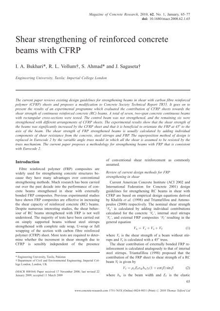
The current paper reviews existing design guidelines for <strong>strengthening</strong> <strong>beams</strong> in shear <strong>with</strong> carbon fibre <strong>reinforced</strong><br />
polymer (<strong>CFRP</strong>) sheets and proposes a modification to Concrete Society Technical Report TR55. It goes on to<br />
present the results <strong>of</strong> an experimental programme which evaluated the contribution <strong>of</strong> <strong>CFRP</strong> sheets towards the<br />
shear strength <strong>of</strong> continuous <strong>reinforced</strong> <strong>concrete</strong> (RC) <strong>beams</strong>. A total <strong>of</strong> seven, two-span <strong>concrete</strong> continuous <strong>beams</strong><br />
<strong>with</strong> rectangular cross-sections were tested. The control beam was not strengthened, and the remaining six were<br />
strengthened <strong>with</strong> different arrangements <strong>of</strong> <strong>CFRP</strong> sheets. The experimental results show that the shear strength <strong>of</strong><br />
the <strong>beams</strong> was significantly increased by the <strong>CFRP</strong> sheet and that it is beneficial to orientate the FRP at 458 to the<br />
axis <strong>of</strong> the beam. The shear strength <strong>of</strong> FRP strengthened <strong>beams</strong> is usually calculated by adding individual<br />
components <strong>of</strong> shear resistance from the <strong>concrete</strong>, steel stirrups and FRP. The superposition method <strong>of</strong> design is<br />
replaced in Eurocode 2 by the variable angle truss model in which all the shear is assumed to be resisted by the<br />
truss mechanism. The current paper proposes a methodology for <strong>strengthening</strong> <strong>beams</strong> <strong>with</strong> FRP that is consistent<br />
<strong>with</strong> Eurocode 2.<br />
Introduction<br />
Fibre <strong>reinforced</strong> polymer (FRP) composites are<br />
widely used for <strong>strengthening</strong> <strong>concrete</strong> structures because<br />
they have many advantages over conventional<br />
<strong>strengthening</strong> methods. Much research has been carried<br />
out over the past decade into the performance <strong>of</strong> <strong>concrete</strong><br />
<strong>beams</strong> strengthened in shear <strong>with</strong> externally<br />
bonded FRP composites. Previous experimental studies<br />
have shown FRP composites are effective in increasing<br />
the shear capacity <strong>of</strong> <strong>reinforced</strong> <strong>concrete</strong> (RC) <strong>beams</strong>.<br />
Despite numerous interesting studies, the shear behaviour<br />
<strong>of</strong> RC <strong>beams</strong> strengthened <strong>with</strong> FRP is not well<br />
understood. The majority <strong>of</strong> tests have been carried out<br />
on simply supported <strong>beams</strong> <strong>with</strong>out steel stirrups<br />
strengthened <strong>with</strong> complete side wrap, U-wrap or full<br />
wrapping <strong>of</strong> the section <strong>with</strong> carbon fibre <strong>reinforced</strong><br />
polymer (<strong>CFRP</strong>) sheet. More tests are required to determine<br />
whether the increment in shear strength due to<br />
<strong>CFRP</strong> is sensibly independent <strong>of</strong> the presence<br />
* Engineering University, Taxila, Pakistan<br />
† Department <strong>of</strong> Civil and Environmental Engineering, Imperial College<br />
London, London, UK<br />
(MACR 800164) Paper received 17 November 2008; last revised 22<br />
January 2009; accepted 11 March 2009<br />
Magazine <strong>of</strong> Concrete Research, 2010, 62, No. 1, January, 65–77<br />
doi: 10.1680/macr.2008.62.1.65<br />
<strong>of</strong> conventional shear reinforcement as commonly<br />
assumed.<br />
Review <strong>of</strong> current design methods for FRP<br />
<strong>strengthening</strong> in shear<br />
Current American Concrete Institute (ACI 2002 and<br />
International Federation for Concrete 2001) design<br />
guidelines for <strong>strengthening</strong> RC <strong>beams</strong> in shear <strong>with</strong><br />
<strong>CFRP</strong> are based on empirical design equations derived<br />
by Khalifa et al. (1998) and Triantafillou and Antonopoulos<br />
(2000) respectively. The nominal shear strength<br />
‘Vn’ is calculated by adding individual contributions<br />
calculated for the <strong>concrete</strong> ‘Vc’, internal steel stirrups<br />
‘Vs’, and external FRP composites ‘Vf’ resulting in the<br />
general equation<br />
Vn ¼ Vc þ Vs þ Vf<br />
(1)<br />
where Vc is the shear strength <strong>of</strong> a beam <strong>with</strong>out stirrups<br />
and Vs is calculated <strong>with</strong> a 458 truss.<br />
The shear contribution <strong>of</strong> externally bonded FRP reinforcement<br />
is calculated analogously to that <strong>of</strong> internal<br />
steel stirrups. Triantafillou (1998) proposed that the<br />
contribution <strong>of</strong> the FRP sheet to shear strength <strong>of</strong> a RC<br />
beam Vf is given by<br />
Vf ¼ rf Ef åfebwzf ð1þcot âÞsin<br />
â (2)<br />
where bw is the beam width and Ef is the elastic<br />
www.<strong>concrete</strong>-research.com 1751-763X (Online) 0024-9831 (Print) # 2010 Thomas Telford Ltd<br />
65
Bukhari et al.<br />
modulus <strong>of</strong> the FRP. The angle â describes the fibre<br />
orientation <strong>with</strong> respect to the longitudinal axis <strong>of</strong> the<br />
beam. The lever zf is taken as 0 . 9 df in Eurocode<br />
format or df in ACI (2002) format where df is the<br />
effective depth <strong>of</strong> FRP reinforcement measured from<br />
the centre <strong>of</strong> the tensile steel. In the current paper, df is<br />
measured to the extreme compressive fibre <strong>of</strong> the FRP<br />
when the FRP does not extend over the full height <strong>of</strong><br />
the beam. The FRP shear reinforcement ratio rf equals<br />
2tf wf /(bwsf ) where tf is the sheet thickness, wf is the<br />
sheet width and sf is the spacing <strong>of</strong> the FRP strips<br />
which equals wf for continuous sheets <strong>of</strong> vertically<br />
oriented FRP.<br />
FRP fails at a lower strain than in its naked state<br />
when bonded to <strong>concrete</strong> owing to either de-bonding or<br />
rupture. Consequently, the design stress is calculated in<br />
FRP in terms <strong>of</strong> an effective strain (åfe) which is given<br />
by<br />
åfe ¼ Råfu<br />
(3)<br />
where R is a reduction factor and åfu is the ultimate<br />
tensile strain <strong>of</strong> FRP.<br />
Calculation <strong>of</strong> effective stress in FRP<br />
Triantafillou (1998) rearranged Equation 2 to give<br />
the effective strain (åfe) in the FRP in terms <strong>of</strong> Vf: He<br />
found that the effective strain (åfe) is a function <strong>of</strong> the<br />
axial rigidity (rf Ef ) <strong>of</strong> FRP. He went on to derive an<br />
empirical relationship between strain and axial rigidity<br />
<strong>with</strong> data from 40 <strong>beams</strong> tested by various researchers.<br />
Khalifa et al. (1998) modified Triantafillou’s (1998)<br />
method for calculating åfe on the basis <strong>of</strong> a slightly<br />
enlarged data base <strong>of</strong> 48 <strong>beams</strong>. The experimental data<br />
used by Khalifa et al. (1998) included two types <strong>of</strong><br />
FRP materials (carbon and aramid) and three different<br />
wrapping configurations (sides only, U-shaped wrapping<br />
and complete wrapping), <strong>with</strong> both continuous<br />
sheets and strips <strong>of</strong> FRP. Khalifa et al. (1998) derived<br />
Equation 4a below from a regression analysis <strong>of</strong> test<br />
data including both FRP rupture and de-bonding failure<br />
modes. They went on to use Equation 4a to define the<br />
effective strain in the FRP at rupture.<br />
R ¼ 0:5622(r f Ef) 2<br />
for Efr f < 1:1 GPa<br />
1:2188(r f Ef) þ 0:778<br />
(4a)<br />
They defined the reduction factor for <strong>CFRP</strong> de-bonding<br />
(only applicable to side and U wrap) as<br />
R ¼ 0:0042ðf9cÞ 2=3 wfe ðtfEfÞ 0: 58<br />
åfudf<br />
(4b)<br />
where wfe is the effective width <strong>of</strong> the <strong>CFRP</strong> sheet<br />
which is taken as<br />
wfe ¼ df nLe (5)<br />
where n ¼ 1 for U wrap and 2 for side wrap. Khalifa et<br />
al. (1998) took the effective bond length Le as<br />
Le ¼ e 6: 134 0 : ½ 58ln ðtfEfÞŠ (6)<br />
Khalifa et al. (1998) took R as the least <strong>of</strong> 0 . 5 (to<br />
control the shear crack width and loss <strong>of</strong> aggregate<br />
interlock), Equation 4a and Equation 4b if applicable.<br />
The lever arm z f in Equation 2 was taken as df . They<br />
proposed that the design shear strength should be obtained<br />
by multiplying each component <strong>of</strong> the nominal<br />
shear strength by strength reduction factors equal to<br />
0 . 85 for Vc and Vs and 0 . 70 for Vf.<br />
Triantafillou and Antonopoulos (2000) presented<br />
equations for åfe which were derived from a regression<br />
analysis <strong>of</strong> data from 75 beam tests. The characteristic<br />
effective strain (åfke ¼ 0 . 8åfe) for fully wrapped <strong>CFRP</strong><br />
sheet (where shear failure is combined <strong>with</strong> or followed<br />
by FRP rupture) is given by<br />
åfke ¼ 0:8 3 0:17 f 2=3<br />
c =r f Ef<br />
0 : 30<br />
åfu<br />
(7)<br />
and for U-shaped or side wrapped <strong>CFRP</strong> (where premature<br />
shear failure occurs due to de-bonding) is<br />
åfke ¼ min 0:8 3 0:65 f 2=3<br />
c =r f Ef<br />
0 : 56<br />
3 10 3 ;0:8 3 0:17 f 2=3<br />
c =r f Ef<br />
0 : 30<br />
åfu<br />
(8)<br />
Equations 7 and 8 should be used <strong>with</strong> Ef in MPa and<br />
zf ¼ 0 . 9df in Equation 2. Equation 7 was derived from<br />
a regression analysis <strong>of</strong> shear failures combined <strong>with</strong> or<br />
followed by FRP fracture. The first term in Equation 8<br />
was derived from a regression analysis <strong>of</strong> shear failures<br />
combined <strong>with</strong> FRP de-bonding. Triantafillou and<br />
Antonopoulos (2000) proposed that in Eurocode format<br />
åfke should be used in Equation 2 in conjunction <strong>with</strong> a<br />
partial factor <strong>of</strong> safety <strong>of</strong> 1 . 3 if FRP de-bonding governs<br />
(i.e. for side or U wraps) or 1 . 2 if fracture governs<br />
(i.e. fully wrapped).<br />
In 2004, The Concrete Society published revised<br />
guidelines for <strong>strengthening</strong> <strong>beams</strong> in shear <strong>with</strong> FRP<br />
in the second edition <strong>of</strong> Technical Report (TR) 55<br />
(Concrete Society, 2003). The revised guidelines are<br />
based on the work <strong>of</strong> Denton et al. (2004) and supersede<br />
the original recommendations in TR55, which<br />
were derived from the work <strong>of</strong> Khalifa et al. (1998)<br />
The contribution <strong>of</strong> the FRP to the shear capacity is<br />
calculated in TR55 (Concrete Society, 2003) <strong>with</strong><br />
Equation 2 <strong>with</strong> an effective value for rf given by<br />
r f ¼ r f (df nltmax=3)=zf : (9)<br />
where n ¼ 0 for fully wrapped sections, 1 for U wrap<br />
and 2 for side wrap and ltmax is the anchorage length<br />
required to develop full anchorage capacity which is<br />
taken as<br />
pffiffiffiffiffiffiffiffiffiffiffiffiffiffiffiffiffiffiffiffi<br />
ltmax ¼ 0:7 ð Þ (10)<br />
Efd tf =f ct<br />
where fct ¼ tensile strength <strong>of</strong> <strong>concrete</strong> ¼ 0 . 21fck (2=3)<br />
66 Magazine <strong>of</strong> Concrete Research, 2010, 62, No. 1
The effective strain in the FRP is taken as the least<br />
pffiffiffiffiffiffiffiffiffiffiffiffiffiffiffiffiffiffi<br />
<strong>of</strong> (a) åfu/2, (b) 0:64 f ct=Efdtf , (c) 0 . 004.<br />
According to TR55, the first strain limit represents<br />
the average FRP strain when fracture occurs. The second<br />
strain limit corresponds to debonding <strong>of</strong> FRP and<br />
the third limit is based on experience and is intended to<br />
limit the loss <strong>of</strong> aggregate interlock due to excessive<br />
crack widths. The design stress in the FRP is obtained<br />
by multiplying the effective strain by the design elastic<br />
modulus which equals the characteristic value divided<br />
by a partial factor <strong>of</strong> safety, which depends on the FRP<br />
type and method <strong>of</strong> application, and which is typically<br />
around 1 . 2.<br />
Zhang and Hsu (2005) presented two equations for<br />
calculating R, the least <strong>of</strong> which is used in Equation 3.<br />
They concluded that the fracture <strong>of</strong> FRP laminates was<br />
far more complicated than expected and that there was<br />
no simple relationship between R and axial rigidity for<br />
FRP fracture. They derived Equation 11 below for bond<br />
failure from a regression analysis <strong>of</strong> <strong>beams</strong> which<br />
failed due to FRP de-bonding:<br />
R ¼ 1:4871ðrfEf = f cÞ<br />
0: 7488<br />
(11)<br />
Zhang and Hsu (2005) also derived an analytical equation<br />
for R from an analysis <strong>of</strong> bond failure which is<br />
similar in principle to that <strong>of</strong> Khalifa et al. (1998).<br />
Assessment and development <strong>of</strong> existing design<br />
recommendations<br />
The present authors assessed the accuracy <strong>of</strong> the<br />
design methods <strong>of</strong> Khalifa et al. (1998), Triantafillou<br />
and Antonopoulos (2000) and TR55 (Concrete Society,<br />
2003) by comparing measured and predicted values <strong>of</strong><br />
Vf (<strong>with</strong> partial factors <strong>of</strong> safety equal to 1) for a<br />
database <strong>of</strong> 97 <strong>beams</strong> strengthened in shear <strong>with</strong> <strong>CFRP</strong>.<br />
The authors’ database includes <strong>beams</strong> strengthened <strong>with</strong><br />
side wrapping, U-shaped wrapping and complete wrapping.<br />
The data for the <strong>beams</strong> <strong>with</strong> side and U wrap are<br />
given in Table 1. Vftest/Vfpred is plotted against the normalised<br />
axial rigidity <strong>of</strong> the <strong>CFRP</strong> in Figures 1(a) to<br />
1(c), which show considerable scatter in the accuracy<br />
<strong>of</strong> the predictions <strong>of</strong> Khalifa et al. (1998), Triantafillou<br />
and Antonopoulos (2000) and TR55 (Concrete Society,<br />
2003). Triantafillou’s (1998) method gives comparatively<br />
low values <strong>of</strong> Vftest/Vfpred for side-wrapped specimens<br />
as Equation 8 does not distinguish between side<br />
and U wrap.<br />
The design method in TR55 (Concrete Society,<br />
2003) differs from the methods <strong>of</strong> Khalifa et al. (1998)<br />
and Triantafillou (1998) in that it does not relate the<br />
strength reduction factor R to the axial rigidity <strong>of</strong> the<br />
FRP. The present authors carried out a regression analysis<br />
to determine whether a statistically significant relationship<br />
exists between the effective strain and the<br />
axial rigidity <strong>of</strong> the FRP for the <strong>beams</strong> in their database.<br />
The test data were separated into two categories<br />
pertaining to rupture and de-bonding <strong>of</strong> FRP. The axial<br />
<strong>Shear</strong> <strong>strengthening</strong> <strong>of</strong> <strong>reinforced</strong> <strong>concrete</strong> <strong>beams</strong> <strong>with</strong> <strong>CFRP</strong><br />
rigidity <strong>of</strong> the <strong>CFRP</strong> rf Ef was normalised by f 9c 2=3 as<br />
Horiguchi and Saeki (1997) showed that the bond<br />
strength between the <strong>concrete</strong> and FRP depends on<br />
f 9c 2=3 . Best-fit curves are plotted between the effective<br />
strain defined in Equation 2 and the normalised axial<br />
rigidity r f Ef = f 9c 2=3 <strong>of</strong> the FRP in Figures 2(a) and (b).<br />
The data points in Figure 2(a) which correspond to<br />
rupture <strong>of</strong> FRP are very scattered indicating that a<br />
simple equation based on regression analysis does not<br />
capture the complexity <strong>of</strong> the data. Figure 2(a) also<br />
shows the effective strains corresponding to the equations<br />
<strong>of</strong> Khalifa et al. (1998) (for åfu ¼ 0.014) and<br />
Triantafillou and Antonopoulos (2000) for FRP fracture.<br />
There seems little justification for these equations<br />
and it seems sufficient to limit åfe to 0 . 4åfu to avoid<br />
<strong>CFRP</strong> fracture. Separate regression analyses are shown<br />
in Figure 2(b) for (a) side wrap and (b) U wrap. Figure<br />
2(b) shows that a simple power equation gives a reasonable<br />
description <strong>of</strong> the relationship between the strength<br />
reduction factor and the axial rigidity <strong>of</strong> <strong>CFRP</strong> in<br />
<strong>beams</strong> which fail due to de-bonding <strong>of</strong> FRP. The majority<br />
<strong>of</strong> the data points lie above the curve when capacity<br />
reduction factors <strong>of</strong> 0 . 7 and 0 . 8 are applied to the lines<br />
<strong>of</strong> best fit in Figure 2(b) for side wrap and U wrap<br />
respectively. The resulting design equations for the effective<br />
strain åfe corresponding to de-bonding are given<br />
by<br />
For side wrap<br />
For U wrap<br />
åfe ¼ 0:7 40:25 rf Ef = f 2=3 ð Þ<br />
c<br />
3 10 3 < 0:4åfu < 0:004<br />
åfe ¼ 0:8 29:14 rf Ef= f 2=3 ð Þ<br />
c<br />
3 10 3 < 0:4åfu < 0:004<br />
0 : 70<br />
0 : 48<br />
(12a)<br />
(12b)<br />
where åfu is the ultimate strain in FRP, rf is the FRP<br />
shear reinforcement ratio, Ef is the elastic modulus <strong>of</strong><br />
FRP (MPa) and f 9c is the compressive strength <strong>of</strong> the<br />
<strong>concrete</strong> (MPa). Equation 12 should be used <strong>with</strong><br />
zf ¼ 0 . 9df in Equation 2.<br />
Equations 12a and 12b were used to calculate Vftest/<br />
Vfproposed for the specimens in Table 1. The resulting<br />
ratios Vftest/Vfproposed are plotted against the normalised<br />
axial rigidity <strong>of</strong> the <strong>CFRP</strong> in Figure 3. Comparison <strong>of</strong><br />
Figures 1(a) to 1(c), Figure 3 and the statistics in Table<br />
1 show that Equation 12 is more reliable than the other<br />
methods <strong>of</strong> which TR55 (Concrete Society, 2003) appears<br />
the best. Figure 4 compares the reduction factors<br />
R (<strong>with</strong> åfu ¼ 0 . 015) given by Equation 12 <strong>with</strong> the<br />
corresponding values given by Khalifa et al. (1998)<br />
(Equation 4a), Triantafillou and Antonopoulos (2000)<br />
(Equation 7) and Zhang and Hsu (2005) (Equation 11).<br />
The method <strong>of</strong> Triantafillou and Antonopoulos (2000)<br />
has the disadvantage <strong>of</strong> not differentiating between side<br />
Magazine <strong>of</strong> Concrete Research, 2010, 62, No. 1 67
Bukhari et al.<br />
Table 1. Comparison <strong>of</strong> measured and predicted Vf : (a) side wrap<br />
Beam no. f 9c:<br />
MPa<br />
Section details FRP properties and wrapping schemes Vftest:<br />
kN<br />
bw: d: df : Ef : ffu: MPa tf 10<br />
mm mm mm GPa<br />
3<br />
and U-wrapped sections. Khalifa et al.’s (1998) Equation<br />
4a gives an upper bound to R, which is frequently<br />
overridden by Equation 4b, which is based on bond<br />
failure. Equation 11 <strong>of</strong> Zhang and Hsu (2005) also<br />
gives an upper bound to R. Figure 4 shows that the<br />
relationship between the effective strain in the FRP and<br />
its axial rigidity is also evident in data from tests<br />
carried out by Khalifa and Nanni (2002) and the current<br />
authors in which the sheet thickness and the width<br />
<strong>of</strong> the beam were not varied. The authors consider there<br />
to be a genuine relationship between the axial rigidity<br />
rf<br />
<strong>of</strong> <strong>CFRP</strong> and åfe which should be accounted for in<br />
design. Therefore, it is suggested that Vf is taken as the<br />
least <strong>of</strong> the values calculated <strong>with</strong> TR55 or Equation 2<br />
<strong>with</strong> åfe from Equation 12 and zf ¼ 0 . 9df.<br />
Experimental programme<br />
Vftest/Vfpredicted<br />
Equation 12 Triantafillou Khalifa TR55<br />
IB(C2) 60 152 267 267 235 3450 0.34 1.80 40.4 0.94 0.67 0.64 0.81<br />
IB(C3) 60 152 267 267 235 3450 0.34 4.46 52.0 0.92 0.58 0.70 0.42<br />
IB(C4) 60 152 267 152 235 3450 0.34 4.46 40.4 1.25 0.78 0.96 0.80<br />
IB(C5) } 60 152 267 267 235 3450 0.34 1.80 60.6 — 0.98 0.69 0.88<br />
IB(C6-45) 60 152 267 267 235 3450 0 . 34 1 . 80 69 . 3 1 . 14 0 . 81 0 . 77 0 . 98<br />
IB(D6-45) 44 152 267 267 235 3450 0.34 1.80 70.9 1.34 0.93 0.97 1.15<br />
A(a) 30 70 100 100 235 3055 — 2.20 13.4 2.33 1.52 — —<br />
A(b) 30 70 100 100 235 3055 — 2.20 11.1 1.94 1.26 — —<br />
A(c) 30 70 100 100 235 3055 — 2 . 20 10 . 7 1 . 88 1 . 22 — —<br />
A(45) 30 70 100 100 235 3055 — 2.20 13.8 1.71 1.11 — —<br />
AD(B4) 32 150 170 120 230 3400 0.17 2.23 19.4 1.29 0.85 5.67 1.11<br />
AD(B5) 31 150 170 120 230 3400 0.17 2.23 21.1 1.42 0.93 6.23 1.22<br />
AD(B6) 34 150 170 170 230 3400 0.17 2.23 41.6 1.90 1.25 1.74 1.25<br />
C(RS90-1) þ 35 150 220 220 150 2400 1.00 6.67 34.3 0.97 0.58 0.55 0.93<br />
C(RS90-2) þ 35 150 220 220 150 2400 1.00 6.67 41.8 1.18 0.71 0.67 1.13<br />
C(RS135-1) þ 35 150 220 220 150 2400 1 . 00 4 . 44 40 . 8 0 . 92 0 . 59 0 . 69 1 . 17<br />
C(RS135-2) þ 35 150 220 220 150 2400 1.00 4.44 46.3 1.05 0.67 0.78 1.33<br />
CZ(T2) 56 260 500 500 238 2400 — 1.23 119.9 1.00 0.88 — —<br />
K(C-BT5) 35 150 355 255 228 3790 0.17 0.88 31.5 1.25 1.14 1.34 1.34<br />
SA(S2) 45 200 260 260 230 3480 0 . 11 0 . 55 68 . 4 2 . 04 2 . 89 2 . 79 3 . 15<br />
SA(S4) 38 200 260 260 230 3480 0.11 1.10 64.2 1.69 1.36 1.48 1.50<br />
T(Sla) 30 70 100 100 235 3300 — 2.20 13.6 2.37 1.54 — —<br />
T(Slb) 30 70 100 100 235 3300 — 2.20 11.3 1.97 1.28 — —<br />
T(S2a) 30 70 100 100 235 3300 — 3.30 15.9 2.45 1.51 — —<br />
T(S2b) 30 70 100 100 235 3300 — 3.30 12.9 1.99 1.23 — —<br />
T(S3a) 30 70 100 100 235 3300 — 4.40 13.2 1.87 1.11 — —<br />
T(S3b) 30 70 100 100 235 3300 — 4.40 10.6 1.50 0.89 — —<br />
T(S1-45) 30 70 100 100 235 3300 — 2.20 14.1 1.74 1.13 — —<br />
T(S2-45) 30 70 100 100 235 3300 — 3.30 15.5 1.69 1.04 — —<br />
T(S3-45) 30 70 100 100 235 3300 — 4.40 12.2 1.22 0.72 — —<br />
TA (S2-45) 65 180 500 500 101 1450 — 6 . 67 200 . 6 1 . 24 0 . 84 — —<br />
TA (S3-45) 50 180 500 500 49 577 — 22.2 324.3 1.96 1.21 — —<br />
TA(S4-45) 49 180 460 460 71 708 — 8.80 212.1 1.68 1.11 — —<br />
TA(SR1-45) 54 180 460 460 71 708 — 4.40 177.9 1.65 1.36 — —<br />
TA(SR2-45) 53 180 460 460 71 708 — 8.80 244.9 1.86 1.24 — —<br />
Uj (5) 24 100 170 170 230 2650 0.10 1.94 20.1 1.68 1.09 4.42 0.96<br />
Uj (6-45) 27 100 170 170 230 2650 0.10 1.94 24.0 1.34 0.88 3.45 0.80<br />
Uj (7) 27 100 170 170 230 2650 0.19 3.90 32.3 2.07 1.24 1.34 0.92<br />
Z(Z4 45) 42 152 200 200 165 2800 1.50 6.20 36.9 0.73 0.44 0.49 1.49<br />
Z(Z4 90) 42 152 200 200 165 2800 1.50 6.20 27.6 0.77 0.47 0.52 1.57<br />
Mean for side wrap 1.54 1.05 1.76 1.19<br />
Standard deviation for<br />
side wrap<br />
0 . 46 0 . 42 1 . 74 0 . 53<br />
( continued)<br />
Test specimens<br />
Seven two-span, continuous RC <strong>beams</strong> <strong>with</strong> a rectangular<br />
cross-section <strong>of</strong> 152 mm by 305 mm and<br />
68 Magazine <strong>of</strong> Concrete Research, 2010, 62, No. 1
Table 1. (continued)<br />
Table 1. Comparison <strong>of</strong> measured and predicted Vf : (b) U wrap<br />
Beam no. f 9c:<br />
MPa<br />
Section details FRP properties and wrapping schemes Vftest:<br />
kN<br />
bw: d: df : Ef : ffu: MPa tf 10<br />
mm mm mm GPa<br />
3<br />
shear span-to-depth ratio (a/d) <strong>of</strong> 2 . 85 were tested.<br />
The effective depth to the steel reinforcement was<br />
267 mm. Three 16 mm diameter bars were provided at<br />
the top and bottom <strong>of</strong> each beam. The yield strength<br />
<strong>of</strong> the reinforcement was 494 MPa. The corresponding<br />
flexural failure load <strong>of</strong> the <strong>beams</strong> is around 500 kN.<br />
No steel stirrups were provided <strong>with</strong>in the interior<br />
shear spans. To ensure shear failure occurred <strong>with</strong>in<br />
the central shear spans, 6 mm diameter steel stirrups<br />
were provided in the outer shear spans at 130 mm<br />
centres. Beam C1 was a control specimen so was not<br />
strengthened. The remaining tests investigated the contribution<br />
<strong>of</strong> different arrangements <strong>of</strong> <strong>CFRP</strong> to the<br />
shear capacity <strong>of</strong> the <strong>beams</strong>. The <strong>beams</strong> were not<br />
<strong>reinforced</strong> <strong>with</strong> internal stirrups <strong>with</strong>in the central<br />
shear spans as the aim was to compare the efficiency<br />
<strong>of</strong> different arrangements <strong>of</strong> <strong>CFRP</strong>. Rectangular sections<br />
were tested since the aim was to compare the<br />
response <strong>of</strong> continuous <strong>beams</strong> <strong>with</strong> that <strong>of</strong> simply<br />
supported rectangular sections tested by others. One<br />
beam was fully wrapped and was tested as a limiting<br />
case to determine the influence <strong>of</strong> the <strong>CFRP</strong> anchorage<br />
length. Specimen C-4 was designed to simulate<br />
the reduced anchorage in an upstand beam. The <strong>CFRP</strong><br />
<strong>Shear</strong> <strong>strengthening</strong> <strong>of</strong> <strong>reinforced</strong> <strong>concrete</strong> <strong>beams</strong> <strong>with</strong> <strong>CFRP</strong><br />
rf<br />
Vftest/Vfpredicted<br />
Equation 12 Triantafillou Khalifa TR55<br />
AD(B-7) 34 150 170 120 230 3400 0.17 2.23 29.3 0.99 1.24 1.10 1.07<br />
AD(B-8) 35 150 170 170 230 3400 0.17 2.23 46.6 1.10 1.37 0.97 1.09<br />
K(CW2) 28 150 255 255 228 3500 0.17 2.20 39.0 0.67 0.85 0.56 0.58<br />
K(CO2) 21 150 255 255 228 3500 0.17 0.88 40.0 1.22 1.46 1.74 1.52<br />
K(CO3) 21 150 255 255 228 3500 0.17 2.20 65.0 1.24 1.58 1.13 0.99<br />
K(BT2) 35 150 355 255 228 3790 0 . 17 2 . 20 65 . 0 1 . 04 1 . 29 0 . 79 0 . 96<br />
K(BT3) 35 150 355 255 228 3790 0.17 2.20 67.5 1.08 1.35 0.82 1.00<br />
K(BT4) 35 150 355 255 228 3790 0.17 0.88 72.0 1.85 2.61 2.19 2.66<br />
K(SW3-2) þ 19 150 255 255 228 3790 0.17 2.20 50.5 0.98 1.26 0.92 0.77<br />
K(SW4-2) þ 19 150 255 255 228 3790 0.17 2.20 80.5 1.56 2.01 1.46 1.23<br />
K(SO3-2) 28 150 255 255 228 3790 0.17 0.88 54.0 1.50 1.95 1.93 2.02<br />
K(SO3-3) 28 150 255 255 228 3790 0.17 1.32 56.5 1.27 1.54 1.35 1.41<br />
K(SO3-4) 28 150 255 255 228 3790 0.17 2.20 67.5 1.17 1.47 0.97 1.01<br />
K(SO3-5) 28 150 255 255 228 3790 0.17 2.20 92.5 1.60 2.02 1.32 1.38<br />
K(SO4-2) 28 150 255 255 228 3790 0.17 0.88 62.5 1.73 2.26 2.24 2.34<br />
K(SO4-3) 28 150 255 255 228 3790 0.17 2.20 90.0 1.56 1.96 1.29 1.35<br />
SA(S3) 41 200 260 260 230 3480 0 . 11 0 . 55 110 . 0 3 . 07 4 . 65 2 . 98 4 . 59<br />
SA(S5) 40 200 260 260 230 3480 0.11 1.10 106.1 1.71 2.24 1.48 2.22<br />
TK(BS2) 35 200 420 420 280 3494 — 0.17 39.2 2.18 2.73 — —<br />
TK(BS5) 37 200 420 420 280 3494 — 0.13 32.7 2.38 2.98 — —<br />
TK(BS6) 36 200 420 420 280 3494 — 0 . 09 30 . 0 3 . 23 4 . 03 — —<br />
Mean for U wrap 1.58 2.04 1.40 1.57<br />
Std dev. for U wrap 0.67 0.94 0.62 0.95<br />
§ Full wrap, þ Includes steel stirrups, IB ¼ Current paper, AD ¼ Adhikary and Mutsuyoshi (2004), A ¼ Antonopoulos (2000), AR ¼ Araki et al.<br />
(1997), C ¼ Chaallal et al. (1998), F ¼ Funakawa et al. (1997), K ¼ Khalifa et al. (1998), Khalifa and Nanni (2000, 2002), OM ¼ Ono et al.<br />
(1997), SA ¼ Sato et al. (1996), TK ¼ Taerwe et al. (1997), T ¼ Triantafillou (1998), Triantafillou and Antonopoulos (2000), TA ¼ Taljsten<br />
(2003), Uj ¼ Uji (1992), U ¼ Umezu et al. (1997), Z ¼ Zhang and Hsu (2005)<br />
sheet was 0 . 34 mm thick. The elastic modulus <strong>of</strong> the<br />
carbon fibres was 234.5 GPa and the ultimate tensile<br />
strength was 3450 MPa. Details <strong>of</strong> the <strong>beams</strong> and reinforcement<br />
are shown in Figure 5.<br />
Concrete mix<br />
Beams C1 to C6 were cast from <strong>concrete</strong> mix ‘A’<br />
which had a 28 day mean compressive cylinder strength<br />
<strong>of</strong> 60 MPa. Beam D6 was cast from <strong>concrete</strong> mix ‘B’<br />
which had a 28 day mean compressive cylinder strength<br />
<strong>of</strong> 44 MPa. Both the mixes consisted <strong>of</strong> type I cement<br />
<strong>with</strong> maximum limestone coarse aggregate sizes <strong>of</strong><br />
19 mm and 13 mm for mixes ‘A’ and ‘B’ respectively.<br />
Strengthening scheme<br />
Figure 5 shows the configurations <strong>of</strong> <strong>CFRP</strong> used in<br />
the tests. The <strong>CFRP</strong> sheets were bonded to the vertical<br />
sides <strong>of</strong> the <strong>beams</strong> in all the <strong>beams</strong> except C5, which<br />
was fully wrapped. Prior to <strong>strengthening</strong>, the beam<br />
surfaces were cleaned <strong>of</strong> loose particles and form lines<br />
by grinding the <strong>concrete</strong> surface <strong>with</strong> an electric grinder.<br />
The edges <strong>of</strong> beam C5 were smoothed to reduce stress<br />
concentrations at these locations owing to the full wrapping<br />
<strong>of</strong> <strong>CFRP</strong> sheet. After surface preparation, the <strong>CFRP</strong><br />
Magazine <strong>of</strong> Concrete Research, 2010, 62, No. 1 69
Bukhari et al.<br />
V / V<br />
V / V<br />
V / V<br />
ftest fpred<br />
ftest fpred<br />
ftest fpred<br />
4·0<br />
3·0<br />
2·0<br />
1·0<br />
0<br />
0<br />
6·0<br />
5·0<br />
4·0<br />
3·0<br />
2·0<br />
1·0<br />
0<br />
0<br />
4·0<br />
3·0<br />
2·0<br />
1·0<br />
0<br />
0<br />
20<br />
20<br />
20<br />
40<br />
40<br />
40<br />
f f<br />
E / f<br />
(a)<br />
60<br />
E / f<br />
(b)<br />
f f<br />
60<br />
E / f<br />
(c)<br />
f f<br />
sheet was cut to the required length and infused <strong>with</strong> two<br />
part epoxy. The surface was brushed and primed <strong>with</strong><br />
one coat <strong>of</strong> epoxy. The saturated <strong>CFRP</strong> sheet was then<br />
applied to the sides <strong>of</strong> the beam at the required positions.<br />
In <strong>beams</strong> C2 to C5, the <strong>CFRP</strong> sheet was applied <strong>with</strong> the<br />
main fibres oriented perpendicular to the longitudinal<br />
axis <strong>of</strong> the beam. In <strong>beams</strong> C6 and D6, the direction <strong>of</strong><br />
the main fibres was oriented at 458 to the longitudinal<br />
axis <strong>of</strong> the beam as shown in Figure 5.<br />
Test set-up<br />
Each beam was simply supported and continuous<br />
over two spans and loaded <strong>with</strong> a concentrated load at<br />
60<br />
(2/3)<br />
c<br />
(2/3)<br />
c<br />
(2/3)<br />
c<br />
80<br />
80<br />
80<br />
Triantafillou side<br />
Triantafillou U<br />
Triantafillou W<br />
Design 1/1·3<br />
100<br />
Khalifa side<br />
Khalifa U<br />
Khalifa W<br />
Design 0·7<br />
100<br />
TR55 side<br />
TR55 U<br />
TR55 W<br />
TR55 Pelligrino side<br />
Design 1/1·2<br />
100<br />
Figure 1. Comparison <strong>of</strong> measured and predicted Vf :<br />
(a) Triantafillou and Antonopoulos’ method; (b)Khalifa et<br />
al.’s method; (c) TR55 method<br />
120<br />
120<br />
120<br />
R<br />
Effective strain 1000ε fe<br />
1·2<br />
1·0<br />
0·8<br />
0·6<br />
0·4<br />
0·2<br />
0<br />
0<br />
25<br />
20<br />
15<br />
10<br />
5<br />
0<br />
0<br />
10<br />
20<br />
y 0·80x<br />
2<br />
R 0·06<br />
20<br />
30<br />
0·12<br />
f f<br />
W<br />
Triantafillou Equation 7<br />
Khalifa Equation 4a<br />
Best fit<br />
the centre <strong>of</strong> each span, as shown in Figure 5. The<br />
load was applied <strong>with</strong> a 1000 kN capacity hydraulic<br />
jack. Linear variable displacement transducers<br />
(LVDTs) were used to measure vertical displacements<br />
at mid-span and over the supports. Strains were also<br />
40<br />
E / f<br />
(a)<br />
Best-fit U<br />
εfe<br />
29·14x<br />
2<br />
R 0·72<br />
Best-fit S<br />
εfe<br />
40·25x<br />
2<br />
R 0·57<br />
40<br />
f f<br />
(2/3)<br />
c<br />
0·48<br />
0·70<br />
60<br />
E / f<br />
(b)<br />
(2/3)<br />
c<br />
50<br />
80<br />
60<br />
70<br />
S<br />
U<br />
Design U<br />
Design S<br />
Best-fit U<br />
Best-fit side<br />
100<br />
Figure 2. Proposed effective strain against normalised axial<br />
rigidity: (a) fracture <strong>of</strong> FRP; (b) de-bonding <strong>of</strong> FRP<br />
V / V<br />
fpred ftest<br />
4·0<br />
3·0<br />
2·0<br />
1·0<br />
0<br />
0<br />
20<br />
40<br />
60<br />
E / f<br />
f f<br />
(2/3)<br />
c<br />
Equation 12a U<br />
Equation 12b side<br />
Pelligrino side<br />
Design 1/1·2<br />
80<br />
100<br />
Figure 3. Comparison <strong>of</strong> measured and predicted Vf for<br />
Equation 12<br />
70 Magazine <strong>of</strong> Concrete Research, 2010, 62, No. 1<br />
80<br />
120<br />
120
R<br />
0·6<br />
0·5<br />
0·4<br />
0·3<br />
0·2<br />
0·1<br />
0·0<br />
0<br />
20<br />
40<br />
p E / f<br />
Proposed side Equation 12a<br />
Proposed U Equation 12b<br />
Triantafillou Equation 8<br />
Khalifa Equation 4a<br />
Zhang Equation 11<br />
Authors’ <strong>beams</strong> S<br />
Khalifa U<br />
measured in the <strong>CFRP</strong> on the vertical face <strong>of</strong> the<br />
beam <strong>with</strong> vertically oriented surface-mounted electrical<br />
resistance strain gauges. The strain gauges were<br />
located along the anticipated line <strong>of</strong> the diagonal shear<br />
crack at distances <strong>of</strong> 127, 330 and 533 mm from the<br />
face <strong>of</strong> the central support. The crack patterns at failure<br />
are shown in Figure 6.<br />
Experimental results and discussion<br />
f f<br />
(2/3)<br />
c<br />
100<br />
Figure 4. Comparison <strong>of</strong> strength reduction factors R<br />
(åfu ¼ 0 . 015)<br />
120<br />
The experimental results indicate that <strong>strengthening</strong><br />
continuous RC <strong>beams</strong> in shear <strong>with</strong> <strong>CFRP</strong> sheet can<br />
be highly effective and that the contribution <strong>of</strong> the<br />
<strong>CFRP</strong> depends on its configuration and orientation. Of<br />
the seven <strong>beams</strong> tested, C1 was a control beam which<br />
was, consequently, not strengthened. Beam C1 failed<br />
at total load <strong>of</strong> 250 kN as a result <strong>of</strong> a shear-tension<br />
failure. The presence <strong>of</strong> <strong>CFRP</strong> sheets was found to<br />
alter the crack pattern from that observed in the control<br />
beam.<br />
Beam C2 was strengthened <strong>with</strong> <strong>CFRP</strong> sheets measuring<br />
304 . 8 mm by 304 . 8 mm, which were applied in<br />
the middle <strong>of</strong> each <strong>of</strong> the internal shear spans as shown<br />
in Figure 5. The beam failed in shear at total load <strong>of</strong><br />
384 . 7 kN, which is 54% greater than the control beam<br />
C1, owing to de-lamination <strong>of</strong> the <strong>CFRP</strong> sheet. Beam<br />
C5 was strengthened <strong>with</strong> a similar configuration <strong>of</strong><br />
<strong>CFRP</strong> sheets to beam C2, but the sheets were fully<br />
wrapped rather than being side wrapped. A shear crack<br />
appeared at the mid-height <strong>of</strong> the beam near the central<br />
support at a load <strong>of</strong> 384 . 7 kN. The crack widened and<br />
travelled towards the internal support along the bottom<br />
face <strong>of</strong> the beam and upwards towards the load point.<br />
Clicking sounds were heard in the <strong>CFRP</strong> sheet when<br />
the load reached 403 . 9 kN, but the presence <strong>of</strong> the<br />
<strong>CFRP</strong> sheet stopped the crack from propagating and<br />
led to the formation <strong>of</strong> a second major diagonal crack<br />
between the load point and the <strong>CFRP</strong> sheet. The second<br />
60<br />
80<br />
<strong>Shear</strong> <strong>strengthening</strong> <strong>of</strong> <strong>reinforced</strong> <strong>concrete</strong> <strong>beams</strong> <strong>with</strong> <strong>CFRP</strong><br />
crack propagated along the tensile reinforcement towards<br />
the central support. De-lamination <strong>of</strong> the <strong>CFRP</strong><br />
sheet was observed on both sides <strong>of</strong> the beam, but the<br />
beam failed as a result <strong>of</strong> <strong>CFRP</strong> sheet rupturing along<br />
<strong>with</strong> <strong>concrete</strong> splitting at the bottom face <strong>of</strong> the beam.<br />
The failure load <strong>of</strong> C5 was 452 kN which is 81% greater<br />
than the control beam C1 and 27% greater than<br />
beam C2. The deflection <strong>of</strong> the beam and the strain in<br />
the <strong>CFRP</strong> sheet were also greater than in beam C2.<br />
Beam C3 was strengthened by complete side wrapping<br />
<strong>with</strong> <strong>CFRP</strong> sheets in the internal shear spans as<br />
shown in Figure 5. On loading, small flexural cracks<br />
appeared in the top face <strong>of</strong> beam above the central<br />
support. The cracks in the side faces <strong>of</strong> the beam were<br />
invisible during the test since they were obscured by<br />
the <strong>CFRP</strong> wrapping. Clicking sounds were heard as the<br />
load was increased and at 365 . 4 kN de-lamination occurred<br />
between the <strong>concrete</strong> and <strong>CFRP</strong> sheet under one<br />
<strong>of</strong> the load points. The beam failed at 423 . 2 kN, which<br />
is 69% greater than the control beam C1, due to delamination<br />
<strong>of</strong> the <strong>CFRP</strong> sheet. In addition, a longitudinal<br />
crack was also observed at the top face <strong>of</strong> the<br />
beam, which is indicative <strong>of</strong> a splitting failure. The<br />
<strong>CFRP</strong> sheet was removed after the test to see the cracking<br />
pattern at failure. The crack pattern was significantly<br />
different from the other <strong>beams</strong> in that the failure<br />
crack travelled along the bottom steel reinforcement,<br />
which is consistent <strong>with</strong> the arching action observed in<br />
the test. Loss <strong>of</strong> bond occurred between the steel reinforcement<br />
and <strong>concrete</strong> which resulted in separation <strong>of</strong><br />
the <strong>concrete</strong> cover at the bottom face <strong>of</strong> the beam.<br />
Beam C4 was strengthened throughout the length <strong>of</strong><br />
the shear span as in beam C3 but the <strong>CFRP</strong> sheets were<br />
only positioned <strong>with</strong>in the tensile (i.e. upper) half <strong>of</strong><br />
the beam depth as shown in Figure 5. The beam failed<br />
at 384.7 kN, which is 54% greater than the control<br />
beam C1, as a result <strong>of</strong> the <strong>concrete</strong> crushing and<br />
splitting along the bottom steel reinforcement and delamination<br />
<strong>of</strong> the <strong>CFRP</strong> sheet in the middle <strong>of</strong> the<br />
interior shear span.<br />
In beam C6, 304 . 8 mm wide <strong>CFRP</strong> sheets were<br />
applied <strong>with</strong> the main fibres oriented almost perpendicular<br />
to the angle <strong>of</strong> the shear cracks at an angle <strong>of</strong><br />
458 to the longitudinal axis <strong>of</strong> the beam as shown in<br />
Figure 5. Beam C6 failed at a load <strong>of</strong> 480 . 9kN,<br />
which is 92% greater than C1, as a result <strong>of</strong> the <strong>CFRP</strong><br />
sheet de-laminating under the loading point. Yielding<br />
<strong>of</strong> the longitudinal reinforcement was observed at failure<br />
along <strong>with</strong> splitting <strong>of</strong> the <strong>concrete</strong> cover at the<br />
bottom face <strong>of</strong> the beam. The failure crack was inclined<br />
at a relatively steep angle <strong>of</strong> 588 to the longitudinal<br />
axis <strong>of</strong> the beam. Beam D6 was strengthened<br />
<strong>with</strong> the same configuration <strong>of</strong> <strong>CFRP</strong> sheet as beam<br />
C6 but the <strong>concrete</strong> compressive strength was 20%<br />
lower than in beam D6. Beam D6 failed at a total<br />
load <strong>of</strong> 461 . 7 kN, which is 7% less than C6, as a<br />
result <strong>of</strong> the <strong>CFRP</strong> sheet de-laminating from the beam<br />
surface.<br />
Magazine <strong>of</strong> Concrete Research, 2010, 62, No. 1 71
Bukhari et al.<br />
Beam C1<br />
Beam C2<br />
Beam C3<br />
Beam C4<br />
Beam C5<br />
Beams C6 and D6<br />
838<br />
Figure 5. Beam configuration details<br />
9 mm dia. steel stirrups<br />
@ 130 mm c/c<br />
(both ends)<br />
762<br />
838<br />
229 305 228<br />
Load<br />
<strong>Shear</strong> strength<br />
The shear strengths <strong>of</strong> the authors’ <strong>beams</strong> are listed<br />
in Table 2. The tests showed that the surface area <strong>of</strong> the<br />
<strong>CFRP</strong> sheet can be minimised while maintaining a considerable<br />
increase in shear capacity. For example, the<br />
strength <strong>of</strong> beam C2 was only 15% less than that <strong>of</strong><br />
beam C3 <strong>with</strong> complete side wrap even though the area<br />
<strong>of</strong> <strong>CFRP</strong> was reduced by 63% in beam C2. Placing the<br />
370<br />
481 357<br />
304<br />
(3 3) 16 mm dia. bars<br />
<strong>CFRP</strong> over half the beam depth <strong>with</strong>in the tensile zone<br />
as in Beam C4 (see Figure 5) increased shear strength<br />
but resulted in a brittle failure mode as shown in Figure<br />
7 and is, therefore, not recommended. Applying <strong>CFRP</strong><br />
<strong>with</strong>in the central half <strong>of</strong> the shear span as in C2<br />
(where the strength was increased by 54%) appears to<br />
be effective in continuous <strong>beams</strong> <strong>with</strong> ratios <strong>of</strong> shear<br />
span to effective depth up to at least 2 . 85. Tests C6 and<br />
D6 showed that shear strength is enhanced considerably<br />
72 Magazine <strong>of</strong> Concrete Research, 2010, 62, No. 1<br />
305<br />
152
Figure 6. Crack pattern in tested <strong>beams</strong><br />
if the <strong>CFRP</strong> sheets are oriented <strong>with</strong> the main fibres<br />
at 458.<br />
Load–deflection behaviour<br />
Figure 7 shows that all the <strong>CFRP</strong> strengthened <strong>beams</strong><br />
were slightly stiffer and deflected more at the ultimate<br />
load than the control beam C1. The largest deflection<br />
occurred in beam C6 where the <strong>CFRP</strong> sheet was applied<br />
<strong>with</strong> the main fibres oriented at 458 to the long-<br />
<strong>Shear</strong> <strong>strengthening</strong> <strong>of</strong> <strong>reinforced</strong> <strong>concrete</strong> <strong>beams</strong> <strong>with</strong> <strong>CFRP</strong><br />
(Beam C1) (Beam C2)<br />
(Beam C3) (Beam C3)<br />
(Beam C4) (Beam C5)<br />
(Beam C6) (Beam D6)<br />
itudinal axis <strong>of</strong> the beam. Beams C1, C2 and C4<br />
showed brittle behaviour, whereas the other <strong>beams</strong><br />
failed in a relatively ductile mode.<br />
Load–strain behaviour<br />
Figure 8 shows the variation in the vertical strains<br />
measured in the <strong>CFRP</strong> at the centre <strong>of</strong> the failed shear<br />
span. The strains were very small prior to diagonal<br />
cracking after which the strain increased rapidly. The<br />
Magazine <strong>of</strong> Concrete Research, 2010, 62, No. 1 73
Bukhari et al.<br />
Table 2. Experimental results<br />
Ultimate load: kN Vexp: kN Vftest: kN Deflection: mm Rstrength Rstrain Failure mode<br />
C1 250 75.0 — 1.9 — — <strong>Shear</strong><br />
C2 384.7 115.4 40.4 2.68 0.18 0.08 Sheet delamination<br />
C3 423.2 127.0 52.0 4.2 0.09 0.16 Sheet delamination<br />
C4 384.7 115.4 40.4 3.9 0.12 0.18 Sheet delamination<br />
C5 452 . 0 135 . 6 60 . 6 4 . 4 0 . 27 0 . 18 Sheet rupture<br />
C6 480.9 144.3 69.3 5.3 0.22 0.32 Sheet delamination<br />
D6 461.7 138.5 70.9 5.0 0.20 0.22 Sheet delamination<br />
Load: kN<br />
600<br />
500<br />
400<br />
300<br />
200<br />
100<br />
0<br />
0<br />
1<br />
2 3<br />
Deflection: mm<br />
4<br />
Figure 7. Load–mid-span deflection curves<br />
Load: kN<br />
600<br />
500<br />
400<br />
300<br />
200<br />
100<br />
0<br />
0<br />
1000 2000 3000 4000<br />
Strain at mid-depth <strong>of</strong> beam: µ s<br />
greatest strains were measured in beam C6 in which<br />
the <strong>CFRP</strong> sheet was applied at 458 to the longitudinal<br />
axis <strong>of</strong> the beam.<br />
Analysis <strong>of</strong> current authors’ test <strong>beams</strong><br />
The contribution <strong>of</strong> the <strong>CFRP</strong> to shear strength was<br />
estimated for each beam by subtracting the shear<br />
strength <strong>of</strong> the control beam from that <strong>of</strong> the strengthened<br />
<strong>beams</strong>. The shear strength <strong>of</strong> the control beam<br />
was reduced by a factor <strong>of</strong> (44/60) 1=3 in the case <strong>of</strong><br />
beam D6 to account for the difference in <strong>concrete</strong><br />
strengths between <strong>beams</strong> C1 and D6. Two different<br />
methods were used to estimate the strength reduction<br />
factor R in Equation 3. First, reduction factors (Rstrain)<br />
were obtained by dividing the peak strain measured in<br />
the FRP by its ultimate strain. Second, strength reduction<br />
factors (Rstrength) were estimated from Equations 1<br />
and 2. The resulting R values are given in Table 2. The<br />
5<br />
C1<br />
C2<br />
C3<br />
C4<br />
C5<br />
C6<br />
D6<br />
6<br />
C1<br />
C2<br />
C3<br />
C4<br />
C5<br />
C6<br />
D6<br />
5000<br />
Figure 8. Load–vertical strain in <strong>CFRP</strong> sheet (mid-depth)<br />
R values derived from the strains are <strong>of</strong> a similar order<br />
<strong>of</strong> magnitude to the values calculated from back substitution<br />
into Equations 1 and 2, but there is no consistent<br />
relationship between the two. The measured and predicted<br />
contributions <strong>of</strong> the <strong>CFRP</strong> to the shear strength<br />
are compared in Table 1, which shows that Equation 12<br />
gives the best prediction <strong>of</strong> Vf. The FRP shear reinforcement<br />
ratio rf was taken as 2tf wf /(bwav) for the<br />
authors’ tests, which are designated <strong>with</strong> the prefix IB<br />
in Table 1, where tf is the sheet thickness, wf is the<br />
sheet width and av is the shear span <strong>of</strong> 762 mm. TR55<br />
gives reasonable predictions <strong>of</strong> Vf for all the <strong>beams</strong><br />
except C3 <strong>with</strong> complete side wrap where Vf is significantly<br />
overestimated.<br />
Application <strong>of</strong> Eurocode 2<br />
The ENV version <strong>of</strong> Eurocode 2 (British Standards<br />
Institution, 1992) included the ‘standard method’ for<br />
calculating the shear strength <strong>of</strong> <strong>beams</strong> which was<br />
equivalent to Equation 1. The ‘standard method’ was<br />
removed from Eurocode 2 (British Standards Institution,<br />
2004) which only gives the variable strut inclination<br />
method for the design <strong>of</strong> shear reinforcement in <strong>beams</strong>.<br />
It is assumed in the variable strut inclination method that<br />
the shear force is entirely resisted by a truss consisting<br />
<strong>of</strong> <strong>concrete</strong> struts acting in compression equilibrated by<br />
shear reinforcement in tension. The angle <strong>of</strong> the <strong>concrete</strong><br />
struts varies from 21.8 to458to the longitudinal<br />
axis <strong>of</strong> the beam depending upon the applied shear<br />
force. For members <strong>with</strong> inclined shear reinforcement,<br />
the design value <strong>of</strong> the shear strength is given by<br />
VRd,s ¼ Aswð0:9dÞfywdðcot Ł þ cot âÞsin<br />
â=s (13)<br />
where Asw is the area <strong>of</strong> steel shear reinforcement; fywd<br />
is the yield strength <strong>of</strong> the shear reinforcement; s is the<br />
spacing <strong>of</strong> the stirrups; Ł is the angle in degrees <strong>of</strong> the<br />
<strong>concrete</strong> strut to the longitudinal axis <strong>of</strong> the beam; â is<br />
the inclination angle <strong>of</strong> shear reinforcement. The value<br />
<strong>of</strong> cot Ł is limited to 1 < cotŁ < 2 . 5. Eurocode 224 defines the maximum shear capacity in terms <strong>of</strong> cotŁ<br />
and the effective crushing strength <strong>of</strong> the <strong>concrete</strong> as<br />
follows for <strong>beams</strong> <strong>with</strong> vertical stirrups<br />
VRd,max ¼ 0:9bwdí f cd= ðcot Ł þ tan ŁÞ<br />
(14)<br />
where í is a strength reduction factor for <strong>concrete</strong> <strong>with</strong><br />
skew cracks and fcd is the design <strong>concrete</strong> strength.<br />
74 Magazine <strong>of</strong> Concrete Research, 2010, 62, No. 1
The variable angle truss model is an idealisation<br />
based on the lower bound theorem <strong>of</strong> plasticity in<br />
which all the shear force is assumed to be resisted by<br />
the stirrups. In reality, the angle <strong>of</strong> the compression<br />
field in the truss is steeper than assumed in Eurocode 2<br />
and part <strong>of</strong> the shear force is resisted by Vc, which is<br />
not constant as assumed in Equation 1. The following<br />
issues are relevant to the application <strong>of</strong> the variable<br />
angle truss model to <strong>beams</strong> strengthened in shear <strong>with</strong><br />
<strong>CFRP</strong>.<br />
(a) Figure 9 shows that Eurocode 2 (British Standards<br />
Institution, 2004) gives greater shear strengths than<br />
Equation 1 if the reinforcement index exceeds a<br />
critical value <strong>of</strong> around twice the minimum value<br />
specified in Eurocode 2.<br />
(b) The area <strong>of</strong> steel shear reinforcement contributing<br />
to the shear strength is assumed to be constant in<br />
the ‘standard method’ but varies <strong>with</strong> cotŁ in<br />
Equation 13. The contribution <strong>of</strong> steel shear reinforcement<br />
to shear strength is reduced when the<br />
beam is strengthened <strong>with</strong> FRP if the design shear<br />
force is sufficiently high to govern the maximum<br />
permissible value <strong>of</strong> cotŁ.<br />
(c) Tests show that internal steel stirrups and external<br />
<strong>CFRP</strong> shear reinforcement are most efficient when<br />
oriented at 458. This can be seen by comparing the<br />
shear strengths <strong>of</strong> the authors’ <strong>beams</strong> C2, C5, C6<br />
and D6 or Chaallal et al.’s (1998) <strong>beams</strong> RS90 and<br />
RS135. The increased efficiency <strong>of</strong> inclined stirrups<br />
is not reflected in Equation 13 which predicts<br />
that changing the orientation <strong>of</strong> the shear reinforcement<br />
FRP from 908 to 458 reduces the shear<br />
strength by 1% if cotŁ¼2 . 5.<br />
(d) The procedure <strong>of</strong> deriving the effective stress<br />
(Eåfe) in <strong>CFRP</strong> from test data <strong>with</strong> Equations 1<br />
and 2 is dubious since Vc is not constant as assumed<br />
and the truss angle is not 458. The procedure<br />
would give very different stresses to the yield<br />
stress if used for <strong>beams</strong> <strong>with</strong> steel stirrups.<br />
Equation 13 can be modified as follows to give the<br />
shear strength <strong>of</strong> <strong>beams</strong> <strong>with</strong>out internal stirrups<br />
strengthened <strong>with</strong> <strong>CFRP</strong><br />
VRd,FRP ¼ Czf bw Efðcot Ł þ cot âÞsin<br />
â (15)<br />
where C is the least <strong>of</strong> either råfeEquation12 or r*åfeTR55<br />
where r is the FRP ratio defined below Equation 2, r*<br />
is defined in Equation 9 and åfe is calculated in accordance<br />
using Equation 12 or TR55 (Concrete Society,<br />
2003) as noted. The following methods were investigated<br />
for calculating the shear strength (V ¼ Vc + Vs +<br />
Vf ) <strong>of</strong> <strong>beams</strong> strengthened <strong>with</strong> <strong>CFRP</strong> <strong>with</strong> Eurocode 2.<br />
(a) Method 1: Vc + Vs was taken as the greatest <strong>of</strong> Vc<br />
or VRd,s from Equation 13 <strong>with</strong> the maximum<br />
permissible value <strong>of</strong> cotŁ corresponding to the<br />
shear capacity <strong>of</strong> the strengthened beam. Vf was<br />
calculated using Equation 15 <strong>with</strong> cotŁ ¼ 1.<br />
<strong>Shear</strong> <strong>strengthening</strong> <strong>of</strong> <strong>reinforced</strong> <strong>concrete</strong> <strong>beams</strong> <strong>with</strong> <strong>CFRP</strong><br />
V/(0·9 f h d)<br />
ck v<br />
0·5<br />
0·4<br />
0·3<br />
0·2<br />
0·1<br />
0<br />
0<br />
Chaallal<br />
Chaallal<br />
Pelligrino<br />
Monti UF90<br />
M2 Chaalal fc 35 MPa<br />
M3 γc 1<br />
M3 γc<br />
1·5<br />
Pelligrino no internal stirrups<br />
No <strong>CFRP</strong><br />
Pelligrino <strong>CFRP</strong> internal stirrups<br />
Internal stirrups<strong>CFRP</strong> No internal stirrups<br />
0·05 0·10 0·15 0·20 0·25<br />
Stirrup index [ Af/( b s) CE ]/( νf<br />
)<br />
sy w f ck<br />
0·30<br />
Figure 9. Comparison between measured and predicted shear<br />
strengths<br />
(b) Method 2: Vc + Vs was taken as Vc + VRd,s where<br />
VRd,s was calculated using Equation 13 <strong>with</strong><br />
cotŁ ¼ 1. Vf was calculated as in (a) above.<br />
(c) Method 3: As (a) above but Vf was calculated <strong>with</strong><br />
Equation 15 using the value <strong>of</strong> cotŁ used for VRd,s<br />
in Equation 13. V ¼ Vc + Vs + Vf was not taken as<br />
less than Vc.<br />
The methods were assessed for <strong>beams</strong> <strong>with</strong>in the<br />
authors’ database <strong>with</strong> U or side wrapping where sufficient<br />
data were available. The database consisted <strong>of</strong> 30<br />
<strong>beams</strong> <strong>reinforced</strong> in shear <strong>with</strong> only <strong>CFRP</strong> (six <strong>beams</strong><br />
from this study, five <strong>beams</strong> from Adhikary and Mutsuyoshi<br />
(2004) (B-4 to B-8 inclusive), eight <strong>beams</strong><br />
from Khalifa and Nanni (2002, 2000) (BT2 to BT5<br />
inclusive and SO3-2 to SO3-4 and SO4-2), nine <strong>beams</strong><br />
from Triantafillou (1998) (S1a, S1b, S2a, S2b, S3a,<br />
S36b, S1-45 to S3-45) and two <strong>beams</strong> from Zhang and<br />
Hsu (2005) (Z4 45, Z4 90)) and 20 <strong>beams</strong> <strong>with</strong> <strong>CFRP</strong><br />
and steel shear reinforcement (four <strong>beams</strong> from<br />
Chaallal et al. (1998), all 11 <strong>beams</strong> from Pelligrino and<br />
Modena (2002) and five <strong>beams</strong> from Monti and Liotta<br />
(2007) (UF90, UF45+A, UF45+D, WS45+, UF90)).<br />
The <strong>beams</strong> <strong>of</strong> Monti and Liotta (2007) and Pelligrino<br />
and Modena (2002) are not included in Table 1. The<br />
<strong>CFRP</strong> was oriented at 908 in all the <strong>beams</strong> except those<br />
<strong>with</strong> 45 in their label where the orientation was 458.<br />
The <strong>beams</strong> <strong>of</strong> Monti and Liotta (2007) had unusually<br />
low <strong>concrete</strong> cube strengths <strong>of</strong> 13 . 3 MPa. The top <strong>of</strong><br />
the <strong>CFRP</strong> was stopped 150 mm below the top <strong>of</strong> these<br />
<strong>beams</strong>, which had an effective depth <strong>of</strong> 410 mm, to<br />
simulate the presence <strong>of</strong> a flange. The top <strong>of</strong> the sheet<br />
was mechanically anchored in all the <strong>beams</strong> except<br />
UF90, which had a comparatively low strength.<br />
The strengths <strong>of</strong> the <strong>beams</strong> are compared in Figure 9<br />
<strong>with</strong> the strengths calculated <strong>with</strong> method 3. Figure 9<br />
shows that method 3 overestimates the strength <strong>of</strong> a<br />
significant number <strong>of</strong> <strong>beams</strong> <strong>with</strong> stirrups and is therefore<br />
not recommended. Method 2 is illustrated in Figure<br />
9 (<strong>with</strong> ªc ¼ 1 . 5 and â ¼ 908) for Chaalal et al.’s<br />
<strong>beams</strong> in which f 9c was 35 MPa. Figures 10(a) and<br />
10(b), in which the material factors <strong>of</strong> safety were<br />
Magazine <strong>of</strong> Concrete Research, 2010, 62, No. 1 75
Bukhari et al.<br />
V / V<br />
V / V<br />
test pred<br />
test pred<br />
2·5<br />
2·0<br />
1·5<br />
1·0<br />
0·5<br />
0<br />
0<br />
2·5<br />
2·0<br />
1·5<br />
1·0<br />
0·5<br />
0<br />
0<br />
M1 no stirrups 90 M1 stirrups 90<br />
M1 no stirrups 45 M1 stirrups Chaalal 45<br />
M1 stirrups Monti 45<br />
50<br />
100<br />
f f<br />
Normalised axial rigidity E / f<br />
(a)<br />
f f<br />
Normalised axial rigidity E / f<br />
(b)<br />
150<br />
(2/3)<br />
c<br />
M2 no stirrups 90 M2 stirrups 90<br />
M2 no stirrups 45 M2 stirrups Chaalal 45<br />
M2 stirrups Monti 45<br />
50<br />
100<br />
150<br />
(2/3)<br />
c<br />
200<br />
200<br />
Figures 10. Comparison between measured and predicted<br />
shear strengths (ªc ¼ 1 . 5): (a) method 1 (Vf ¼ minimum from<br />
TR55 or Equation 12); (b) method 2 (Vf ¼ minimum from<br />
TR55 or Equation 12)<br />
taken as 1.5 for <strong>concrete</strong> and 1.0 for steel and <strong>CFRP</strong>,<br />
show that methods 1 and 2 give similar results for the<br />
<strong>beams</strong> in the database. Figures 9 and 10 show all three<br />
methods are less conservative for <strong>beams</strong> <strong>with</strong> internal<br />
steel shear reinforcement, which suggests that the principle<br />
<strong>of</strong> superposition assumed in Equation 1 is not<br />
strictly valid due to strain incompatibility. The reduced<br />
efficiency <strong>of</strong> <strong>CFRP</strong> in <strong>beams</strong> <strong>with</strong> internal stirrups is<br />
related to two fundamental issues. First, the presence <strong>of</strong><br />
internal stirrups changes the crack pattern. A single<br />
dominant shear crack tends to form in <strong>beams</strong> <strong>with</strong>out<br />
internal stirrups strengthened <strong>with</strong> <strong>CFRP</strong> whereas multiple<br />
parallel shear cracks form in <strong>beams</strong> <strong>with</strong> internal<br />
stirrups. The influence <strong>of</strong> stirrups on the crack pattern,<br />
and consequently the anchorage <strong>of</strong> the <strong>CFRP</strong>, which<br />
determines its effective area, is not included in the<br />
design methods discussed in this paper or that <strong>of</strong> Monti<br />
and Liotta (2007).<br />
Second, methods 1 to 3 which utilise the lower<br />
bound theorem <strong>of</strong> plasticity, assume<br />
(a) that the internal stirrups yield at failure; and<br />
(b) that the effective strain in the <strong>CFRP</strong> at failure is<br />
independent <strong>of</strong> the area <strong>of</strong> internal shear reinforcement.<br />
Assumption (a) is only credible if the strain in the<br />
<strong>CFRP</strong> at failure is sufficient for the internal stirrups to<br />
yield. Strain measurements such as those in Figure 8<br />
suggest this is likely to be the case unless the axial<br />
rigidity <strong>of</strong> the <strong>CFRP</strong> is very high. In methods 1 to 3,<br />
Equation 13 is used to calculate Vc + Vs (<strong>with</strong> cotŁ<br />
calculated in terms <strong>of</strong> the shear capacity <strong>of</strong> the<br />
strengthened beam) whereas in method 2, Vc + Vs is<br />
taken as the design shear strength <strong>of</strong> the un-strengthened<br />
beam. Providing the stirrups yield, both approaches<br />
imply Vc + Vs is independent <strong>of</strong> the strain in<br />
the stirrups, which is not generally the case since shear<br />
failure is relatively brittle. In reality, loss <strong>of</strong> aggregate<br />
interlock is likely to reduce Vc + Vs if the crack widths<br />
in the strengthened beam are greater than in the unstrengthened<br />
beam at failure. Vc + Vs is also likely to<br />
reduce if the strain in the internal stirrups at failure is<br />
less in the strengthened than un-strengthened beam.<br />
Figure 9 shows that the variable angle truss model in<br />
Eurocode 2 can give significantly higher shear<br />
strengths than the ‘standard method’ for <strong>beams</strong> <strong>with</strong><br />
internal steel stirrups. It follows that method 1 can give<br />
significantly higher strengths for strengthened <strong>beams</strong><br />
<strong>with</strong> <strong>CFRP</strong> than method 2 which calculates Vs + Vc<br />
using the ‘standard method’. The current authors consider<br />
it unwise to take advantage <strong>of</strong> this increase in<br />
strength for reasons discussed above. Therefore, it is<br />
suggested in the absence <strong>of</strong> further test data to the<br />
contrary that method 2 is used to assess the shear<br />
strength <strong>of</strong> <strong>beams</strong> strengthened <strong>with</strong> <strong>CFRP</strong>.<br />
Conclusions<br />
This paper describes a series <strong>of</strong> six tests on continuous<br />
<strong>beams</strong> strengthened in shear <strong>with</strong> <strong>CFRP</strong>. The tests<br />
showed that it is beneficial to orientate the fibres in the<br />
<strong>CFRP</strong> sheets at 458 so that they are approximately<br />
perpendicular to the shear cracks. The tests also support<br />
the hypothesis that the efficiency <strong>of</strong> <strong>CFRP</strong> reduces<br />
<strong>with</strong> its axial rigidity. TR55 (Concrete Society, 2003) is<br />
unique among the design methods considered in this<br />
paper in not relating the effective strain in <strong>CFRP</strong> to its<br />
axial rigidity. Consequently, TR55 (see Figure 1(c))<br />
was found significantly to overestimate Vf in some<br />
<strong>beams</strong> including ones tested by the current authors and<br />
Pelligrino and Modena (2002). Therefore, it is suggested<br />
that TR55 should be modified to include Equations<br />
12a and 12b, which relate the effective strain in<br />
<strong>CFRP</strong> to its axial rigidity in side and U-wrapped sections<br />
respectively.<br />
It is shown that the variable angle truss model in<br />
Eurocode 2 can overestimate the shear strength <strong>of</strong><br />
<strong>beams</strong> <strong>with</strong> internal stirrups that are strengthened <strong>with</strong><br />
<strong>CFRP</strong>. This implies <strong>CFRP</strong> strengthened <strong>beams</strong> can have<br />
76 Magazine <strong>of</strong> Concrete Research, 2010, 62, No. 1
insufficient ductility for the lower bound theorem <strong>of</strong><br />
plasticity to be valid. Therefore, it is recommended that<br />
shear strength is calculated by adding the individual<br />
contributions calculated for the <strong>concrete</strong> Vc, internal<br />
steel stirrups Vs, and <strong>CFRP</strong> Vf <strong>with</strong> Vs and Vf calculated<br />
<strong>with</strong> a 458 truss because this reduces the ductility<br />
demand on the beam.<br />
References<br />
ACI (American Concrete Institute) (2002) Guide for the Design and<br />
Construction <strong>of</strong> Externally Bonded FRP Systems for Strengthening<br />
Concrete Structures. ACI, Farmington Hills, Michigan, USA, 2002.<br />
ACI Committee 440.<br />
Adhikary BB and Mutsuyoshi H (2004) Behavior <strong>of</strong> <strong>concrete</strong> <strong>beams</strong><br />
strengthened in shear <strong>with</strong> carbon-fiber sheets. Journal <strong>of</strong> Composites<br />
for Construction 8(3): 258–264.<br />
Antonopoulos CP (2000) <strong>Shear</strong> Strengthening <strong>of</strong> Reinforced Concrete<br />
Structures using Composite Materials. Diploma thesis, Department<br />
<strong>of</strong> Civil Engineering, University <strong>of</strong> Patras, Greece.<br />
Araki N, Matsuzaki Y, Nakano K, Kataoka T and Fukuyama H<br />
(1997) <strong>Shear</strong> capacity <strong>of</strong> retr<strong>of</strong>itted RC members <strong>with</strong> continuous<br />
fiber sheets. Proceedings <strong>of</strong> the Third Symposium on Non-Metallic<br />
(FRP) Reinforcement for Concrete Structures, Japan 1: 515–522.<br />
British Standards Institution (1992) ENV 1992-1, Eurocode2: Design<br />
<strong>of</strong> Concrete Structures: General Rules for Buildings. BSI, London,<br />
1992.<br />
British Standards Institution (2004) Eurocode 2-1: Design <strong>of</strong> Concrete<br />
Structures: General Rules for Buildings. BSI, London, 2004.<br />
Chaallal O, Nollet MJ and Perraton D (1998) <strong>Shear</strong> <strong>strengthening</strong> <strong>of</strong><br />
RC <strong>beams</strong> by externally bonded side <strong>CFRP</strong> strips. Journal <strong>of</strong> Composites<br />
for Construction 2(2): 111–113.<br />
Concrete Society (2003) Design Guidance for Strengthening Concrete<br />
Structures Using Fibre Composite Materials. Concrete Society,<br />
Camberley, 2003. Technical Report 55.<br />
Denton SR, Shave JD and Porter AD (2004) <strong>Shear</strong> <strong>strengthening</strong> <strong>of</strong><br />
<strong>reinforced</strong> <strong>concrete</strong> structures using FRP composites. In Advanced<br />
Polymer Composites for Structural Applications in Construction<br />
(Holloway LC, Chrssanthopoulos MK and Moy SSJ (eds)). Woodhead<br />
Publishing, Cambridge, pp. 134–143.<br />
Funakawa I, Shimono K, Watanbe T, Asada S and Ushijima S (1997)<br />
Experimental study on shear <strong>strengthening</strong> <strong>with</strong> continuous fiber<br />
reinforcement sheet and methyl methacrylate resin. Non-Metallic<br />
(FRP) Reinforcement for Concrete Structures. Japan Concrete Institute,<br />
Tokyo, Vol. 1, pp. 475–482.<br />
Horiguchi T and Saeki N (1997) Effect <strong>of</strong> test methods and quality <strong>of</strong><br />
<strong>concrete</strong> on bond strength <strong>of</strong> <strong>CFRP</strong> sheet. Proceedings <strong>of</strong> the Third<br />
Symposium on Non-Metallic (FRP) Reinforcement for Concrete<br />
Structures, Japan 1: 265–270.<br />
International Federation for Concrete (fib) (2001) Externally Bonded<br />
<strong>Shear</strong> <strong>strengthening</strong> <strong>of</strong> <strong>reinforced</strong> <strong>concrete</strong> <strong>beams</strong> <strong>with</strong> <strong>CFRP</strong><br />
FRP Reinforcement for RC Structures. The International Federation<br />
for Concrete, Lausanne, 2001.<br />
Khalifa A and Nanni A (2000) Improving shear capacity <strong>of</strong> existing<br />
RC T-section <strong>beams</strong> using <strong>CFRP</strong> composites. Cement and Concrete<br />
Composites 22(2): 165–174.<br />
Khalifa A and Nanni A (2002) Rehabilitation <strong>of</strong> rectangular simply<br />
supported RC <strong>beams</strong> <strong>with</strong> shear deficiencies using <strong>CFRP</strong> composites.<br />
Construction and Building Materials 16(3): 135–146.<br />
Khalifa A, Gold W, Nanni A and Abdel-Aziz MI (1998) Contribution<br />
<strong>of</strong> externally bonded FRP to the shear capacity <strong>of</strong> RC flexural<br />
members. Journal <strong>of</strong> Composites for Construction 2(4): 195–202.<br />
Monti G and Liotta M (2007) Tests and design equations for FRP<br />
<strong>strengthening</strong> in shear. Construction and Building Materials 21(4):<br />
799–809.<br />
Ono K, Matsumura M, Sakanishi S and Miyata K (1997) Strength<br />
Improvement <strong>of</strong> RC bridge piers by carbon fiber sheet. In Non-<br />
Metallic (FRP) Reinforcement for Concrete Structures. Japan Concrete<br />
Institute, Tokyo, Vol. 1, pp. 563–570.<br />
Pelligrino C and Modena C (2002) Fiber <strong>reinforced</strong> polymer shear<br />
<strong>strengthening</strong> <strong>of</strong> <strong>reinforced</strong> <strong>concrete</strong> <strong>beams</strong> <strong>with</strong> transverse reinforcement.<br />
Journal <strong>of</strong> Composites for Construction 6(21): May,<br />
104–111.<br />
Sato Y, Ueda T, Kakuta Y and Tanaka T (1996) <strong>Shear</strong> reinforcing<br />
effect <strong>of</strong> carbon fiber sheet attached to side <strong>of</strong> <strong>reinforced</strong> <strong>concrete</strong><br />
<strong>beams</strong>. Advanced Composite Materials in Bridges and Structures<br />
(El-Badry MM (ed.)), CSCE, Montreal, Canada, pp. 621–627.<br />
Taerwe L, Khalil H and Matthys S (1997) Behaviour <strong>of</strong> RC <strong>beams</strong><br />
strengthened in shear by external <strong>CFRP</strong> sheets. In Non-Metallic<br />
(FRP) Reinforcement for Concrete Structures. Japan Concrete Institute,<br />
Tokyo, Vol. 1, pp. 483–490.<br />
Triantafillou TC (1998) <strong>Shear</strong> <strong>strengthening</strong> <strong>of</strong> <strong>reinforced</strong> <strong>concrete</strong><br />
<strong>beams</strong> using epoxy-bonded FRP composites. ACI Structural Journal<br />
95(2): Mar.–Apr., 107–115.<br />
Triantafillou TC and Antonopoulos CP (2000) Design <strong>of</strong> <strong>concrete</strong><br />
flexural members strengthened in shear <strong>with</strong> FRP. Journal <strong>of</strong> Composites<br />
for Construction 4(4): 198–205.<br />
Taljsten B (2003) Strengthening <strong>concrete</strong> <strong>beams</strong> for shear <strong>with</strong> <strong>CFRP</strong><br />
sheets. Construction and Building Materials 17(1): 15–26.<br />
Uji K (1992) Improving shear capacity <strong>of</strong> existing <strong>reinforced</strong> <strong>concrete</strong><br />
members by applying carbon fiber sheets. Transactions <strong>of</strong> the<br />
Japan Concrete Institute 14: 253–266.<br />
Umezu K, Fujita M, Nakai H and Tamaki K (1997) <strong>Shear</strong> behaviour<br />
<strong>of</strong> RC <strong>beams</strong> <strong>with</strong> aramid fiber sheet. Proceedings <strong>of</strong> the Third<br />
Symposium on Non-Metallic (FRP) Reinforcement for Concrete<br />
Structures, Japan, 491–498.<br />
Zhang Z and Hsu T (2005) <strong>Shear</strong> <strong>strengthening</strong> <strong>of</strong> <strong>reinforced</strong> <strong>concrete</strong><br />
<strong>beams</strong> using carbon-fiber-<strong>reinforced</strong> polymer laminates. Journal <strong>of</strong><br />
Composites for Construction 9(2): 158–169.<br />
Discussion contributions on this paper should reach the editor by<br />
1 July 2010<br />
Magazine <strong>of</strong> Concrete Research, 2010, 62, No. 1 77