Download OWNERS HANDBOOK 90 V9A1M Early Model PDF File
Download OWNERS HANDBOOK 90 V9A1M Early Model PDF File
Download OWNERS HANDBOOK 90 V9A1M Early Model PDF File

Create successful ePaper yourself
Turn your PDF publications into a flip-book with our unique Google optimized e-Paper software.
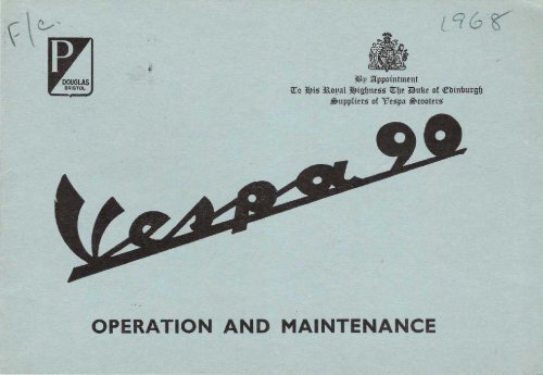
J£JP ~ppointment<br />
~o ~i~ 3lo!,al ~igfJne55 ~~e 3iulte of celJinfJutg~<br />
j!luppIitts of 1:Tespa~tootets<br />
OPERATION AND MAINTENANCE
OPERATION AND MAINTENANCE<br />
1Dp %lppointment<br />
~o JIJi5'.nopaI JIJig~ne5'5'~~e ;auke of ~binbutg~<br />
35>lIppIiet5' of 17espa ~tootttS<br />
DOUGLAS (SALES & SERVICE) LTD., KINGSWOOD, BRISTOL<br />
Telephone 67-1881<br />
DIVISION OF THE WESTINGHOUSE BRAKE AND SIGNAL COMPANY LIMITED
NOTICE<br />
We trust that your Vespa will give you excellent service, and will satisfy your every need.<br />
This booklet, in which the simple instructions for operation and maintenance can be found,<br />
will enable you to understand and use your machine in the most advantageous manner.<br />
To keep your VESPA in perfect running order and not to invalidate the guarantee offered<br />
by the contract, it is advisable to entrust repairs only to retailers or authorised service stations.<br />
Demand original VESPAspare parts exclusively., All VESPAsparesare madeof the samematerial,<br />
have undergone the same machining steps and inspections as the components of your VESPA.<br />
This means guarantee for long life and normal performance of your machine and for your personal<br />
safety.<br />
Special care should be taken with regard to fuel mixture which should consist of a good<br />
quality petrol and oil of make, grade and in the amount prescribed in this booklet, page 28.<br />
SERVICE EXCHANGE<br />
Ask your Dealer for full particulars relating to the Service Exchange Scheme. The use of<br />
the facilities we offer through this medium ensures an economical, speedy, and reliable means<br />
of carrying out repairs when such become necessary.<br />
2-
INDEX OF MAIN DIRECTIONS<br />
Introduction ... ... ... page 2 Lubrication chart ... .. . ... page 28<br />
Layout of controls<br />
Technicaldata ...<br />
...<br />
...<br />
...<br />
...<br />
..<br />
..<br />
5<br />
6<br />
Operating instructions: Faultfinding<br />
... ... ... ... .. 32<br />
Identification detai I ... ... .. 10 Engine: description ... ... .. 34<br />
Operating instruction ... ... .. 11<br />
Tyre pressures<br />
Running-in<br />
...<br />
...<br />
...<br />
...<br />
...<br />
...<br />
..<br />
..<br />
11<br />
13<br />
Chassis: description<br />
Wiring diagram ...<br />
...<br />
...<br />
...<br />
...<br />
..<br />
..<br />
34<br />
36<br />
Maintenance ... ... ... .. 16 Electricalequipment ... ... .. 38<br />
The descriptions and illustrations in this booklet are not to be taken as binding on the Manufacturer. The essential<br />
features of the model described and illustrated herein remaining unaltered, Douglas (Sales & Service) Ltd. reserve<br />
therefore the right to carry out at any moment, without being obliged to bring this booklet up..to..date in due course,<br />
modification that may occur concerning machine units and parts, or delivery of accessories, that the Firm deems to<br />
be convenient on improvement purposes or for what may concern manufacturing or commercial requirements.<br />
-3
4-<br />
Fig. I - Vespa <strong>90</strong>
Fig.2 - Installationof controls and transmissions<br />
I. Clutch control (lever) and gear change (twist grip) - 2. Front<br />
brake lever - 3. Throttle twist trip. 4. Main switch unit. 5. Front<br />
brake shoes- 6. Rear brake pedal- 7. Kickstarter - 8. Gear selector<br />
and gear control adjusting screws . 9. Rear brake shoe - 10.<br />
Clutch . 11. Carburettor and air cleaner - 12. Choke control<br />
13. Fuel Tap.<br />
-5
L<br />
TECHNICAL DATA<br />
Consumption: (CUNA Standards) approx.<br />
156 mls.jimp. gal.. petrol-oil mixture i.e.<br />
2% oil.<br />
Max. Speed: (CUNA Standards) 43.5 m.p.h.<br />
Carrying capacity 2 persons<br />
Range 174 miles<br />
Max fuel capacity: 1.15 imp galls. incl. 0.15<br />
imp. galls. reserve<br />
DIMENSIONS<br />
Wheel base<br />
Handlebar width<br />
Total length<br />
1160mm. (45.2")<br />
610 mm. (23.9")<br />
1650mm. (64.9")<br />
Max. height<br />
Min. ground clearance<br />
Turning radius<br />
Total dry weight<br />
995 mm. (39.17")<br />
225 mm. ( 8.85")<br />
1650mm. (64.9")<br />
70 Kg. (157 Ibs.)<br />
Engine: Displacement 88.5 C.c.- 5.4 cu. in. -<br />
(Bore 47 mm. - 1.85" - Stroke 51 mm. -<br />
2.0" - Compression ratio I:7.2; Two-stroke<br />
rotary distribution).<br />
H.T. flywheel magneto coil ignition.<br />
Spark advance: 19° :J: 1° before T.D.C.<br />
Sparking plug: Recommendations see p. 38.<br />
Note.- The fuel consumption and maximum speed figures must not be accepted as binding.<br />
Many factors outside our control can considerably affect them once the machine is in the hands<br />
of the owner and on the road.<br />
6-
Fig. 3 .. Engine section<br />
I. Group carburettor air cleaner .. 2. Piston .. J. Crankshaft<br />
4. Clutch.. 5. Mainshaft and gear pinion assy. .. 6. Gear shlfter<br />
7. Flywheel magneto.. 8. Kicksurter.. 9. Crankcase swinging arm<br />
clutch side (pivoted to frame).<br />
-7
I<br />
..<br />
I<br />
Fig. 4 - Steering lock<br />
l I. Normal position - 2. Locked position<br />
8-<br />
~ ... ~<br />
Fig. 5 - Dual Seat (for pivoting the seat on its forward edge push<br />
thl lever indicated by arrow).
A: Open the fuel tap - B: Select neutral - C: Pull<br />
out the Choke control rod (with cold engine) - D: Bring<br />
throttle twist grip to idling position . E: Depress<br />
the Kickstarter.<br />
B /-....<br />
.-. ,~<br />
'-J<br />
Fig. 6 - Starting Instructions<br />
-9
IDENTIFICATION DATA The chassis prefix and serial number identify<br />
Each vehicle bears a Serial No. with a specific<br />
production series stamped on the frame and<br />
engine. as indicated in figs. 21 and 22.<br />
10 -<br />
the vehicle as prescribed<br />
numbers must be quoted<br />
spare parts.<br />
Fig. 21 - Serial number stamped on engine. Fig. 22 - Serial number stamped on frame.<br />
by law; these<br />
when ordering
OPERATING INSTRUCTIONS<br />
Before operating the vehicle: unscrew the plug on the gear box marked "aLia"<br />
(fig. 18)and check that the oil is level with the hole when the vehicle is standing upright.<br />
- Check tyre pressure:<br />
Front (17 p.s.i.): Rear (23 p.s.i.) solo;<br />
Rear (33 p.s.i.): with pillion passenger.<br />
OPERATION<br />
INSTRUCTIONS<br />
NOTES<br />
STEERI NG LOCK<br />
(a) Locking the<br />
scooter.<br />
(b) Unlocking the<br />
scooter.<br />
To lock the vehicle it is necessary to turn the<br />
handlebars in anticlockwise direction up to<br />
the limit stop; rotate the key and push inwards,<br />
so that it thrusts the sliding bar<br />
against the steering column.<br />
To ease the insertion of the sliding bar into<br />
the hole of the steering column, slightly<br />
turn the handlebars from the limit stop<br />
clockwise.<br />
To release the handlebars, insert the key<br />
in the lock, turn it to the left and pull it<br />
back; then tu rn the hand lebars in the normal<br />
position.<br />
When the handlebars<br />
are locked the<br />
key will now spring<br />
back to its original<br />
position and can be<br />
extracted.<br />
It can be extracted<br />
from the lock even<br />
if the handlebars are<br />
free.<br />
The steering Jock<br />
should not be lubricated.<br />
-11
OPERATION<br />
FUEL SUPPLY<br />
STARTING<br />
SETTING THE<br />
SCOOTER IN<br />
MOTION<br />
GEAR CHANGE<br />
12-<br />
OPERATING INSTRUCTIONS<br />
INSTRUCTIONS<br />
Ensure that the fuel tank breather<br />
clean. Use a mixture 2 % by<br />
is always<br />
volume<br />
during and after running-in.<br />
- Carry out the instructions indicated on<br />
fig. 6. Do not use the choke when the<br />
-<br />
engine is warm; as soon as the engine<br />
is running smoothly bring the choke<br />
control back to its normal position.<br />
With the engine running at idling speed<br />
declutch and rotate the gear change<br />
twist grip to the position of first gear<br />
(fig. 6). For setting the vehicle in motion<br />
slowly let in the clutch and gradually open<br />
the throttle.<br />
- Close the throttle, declutch and rotate<br />
the gear change grip to a higher or lower<br />
gear, as the case may be (fig. 7).<br />
NOTES<br />
In case of hard<br />
starti ng see page<br />
32.<br />
Do not attempt to<br />
ride the vehicle unless<br />
the handlebars<br />
rotate freely.<br />
When It is necessary<br />
to slow down<br />
do not hesitate in<br />
changing to a lower<br />
gear.
OPERATING INSTRUCTIONS<br />
OPERATION INSTRUCTIONS NOTES<br />
STOPPING THE<br />
ENGINE<br />
- Before stopping the engine change to<br />
"neutral" and then operate the cut-out<br />
button on the switch unit.<br />
RUNNING-IN PERIOD<br />
Up to I,000 miles the machine should never be driven at a speed exceeding 35<br />
m.p.h. It is important of course at all times never to let the engine labour but<br />
during its early life it is doubly important. Use your gear-box freely; never under<br />
any circumstances allow the motor to work hard.<br />
After first 600 miles change oil in gear box (see page 28) and check that all nuts and<br />
bolts are tight.<br />
- 13
~I f:!<br />
\J<br />
Fig.7- Gear Operation<br />
I. Gear change twist grip - 2. Clutch control lever - 3. Gear<br />
change cables - 4. Gear shllter - 5. Selector grou p - 6. Ist gear<br />
7. 2nd gear - 8. Top gear - 9. Helical gear - 10. Clutch - 11. Main<br />
shalt - 12. Stirrup lor gear change.<br />
N.B. - The position I - 2 - 3 on the gear change twist grip correspond<br />
respectively co bottom, 2nd and 3rd gear: the" 0 .,<br />
indicates neutral.
~Fig.8 - Fuel supply_anddistribution diagram<br />
I. Fuel Tap: (A) Reserve; (B) Open; (C) Closed. 2. Throttle<br />
slide set screw. 3. Slow running adjuster screw - 4. Slow running<br />
jet - S. Starter valve - 6. Slow running jet air Bleed - 7. Air filter<br />
8. Main let air Bleed. 9. Starter jet. 10. Float. 11. Main jet<br />
12. Throttle slide. 13. Inlet port. 14. Transfer ports. 15. Exhaust<br />
port.<br />
14 7<br />
11 10 - 15<br />
8
OPERATING AND MAINTENANCE INSTRUCTIONS<br />
STARTING UP when the engine is<br />
flooded:<br />
In the case of difficulties caused by flooding<br />
(presence of unvaporised mixture in the<br />
cylinder),<br />
used:<br />
the following methods can be<br />
- Attempt push starting: select the 2nd<br />
gear, declutch, push the vehicle to a<br />
-<br />
certain speed, sharply release the clutch<br />
and when the engine starts declutch.<br />
Close the fuel tap. remove the sparking<br />
plug (fig. 13) and clean; then kick over<br />
the engine several times. Screw in the<br />
sparking plug securely, open the fuel<br />
tap and kick over the engine.<br />
16-<br />
ADJUSTMENTS ON CARBURETTOR<br />
For adjusting the idling speed turn the slow<br />
running adjuster screw (fig. 8 No. 2).<br />
- On the carburettor body a set screw is<br />
provided for adjusting the throttle cable<br />
play; this screw is to be reset only if<br />
necessary or on dismantling and reassembly<br />
operations.<br />
- On the carburettor body is a spring<br />
loaded volume control screw (fig.8, No. 3).<br />
In order not to influence the engine<br />
running at idle speed, we recommend<br />
that owners should avoid resetting<br />
this screw. Any alteration should<br />
preferably be entrusted to a Service<br />
Station.
Fig. 9 - Removing wheel from vehicle Fig. 10 - Brake adjustment<br />
- 17
18 -<br />
Fig. 11 . Tyre removal
OPERATION<br />
CHANGING<br />
WHEELS AND<br />
TYRES<br />
BRAKE ADJUST-<br />
MENT<br />
OPERATING AND MAINTENANCE INSTRUCTIONS<br />
INSTRUCTIONS<br />
- For dismantling the wheels from the<br />
vehicle remove the bolts as indicated<br />
in fig. 9.<br />
On reassembly tighten said bolts alternately<br />
and progressively.<br />
- When a tyre has to be removed, first<br />
deflate and then remove the nuts joining<br />
the two wheel rims (fig. 11).<br />
- Adjust set screws indicated in fig. 10,<br />
keeping in mind that when the brake lever<br />
or pedal are in the off position the wheels<br />
should rotate freely; the braking action<br />
should begin immediately on operating<br />
the respective controls.<br />
NOTES<br />
The front and rear<br />
wheel are interchangeable<br />
one with<br />
another on condition<br />
that the tyre pressures<br />
are regulated accord..<br />
ingly (page 11).<br />
- 19
20 -<br />
Fig. 12 - Installation of engine and suspension<br />
I. Steering column and (ront suspension - 2. Engine- 3. Crankcase<br />
dutch side with sWinging arm pivoted to frame.. 4. Rear supsension<br />
spring and hydraulic damper assy. .. S. Bolt securing carburettor<br />
6. Bolt securing damper of rear suspension - 7. Nut securing<br />
engine.
OPERATION<br />
SPARKPLUG<br />
REMOVAL<br />
CHANGING OIL<br />
IN GEAR CASE<br />
DISMANTLI NG<br />
AIR FILTER<br />
OPERATING AND MAINTENANCE INSTRUCTIONS<br />
INSTRUCTIONS<br />
- To remove the spark-plug. rotate the knob<br />
and remove the panel; disconnect the H.T.<br />
lead and extract the spark-plug using the<br />
box wrench as indicated in fig. 13.<br />
- Drain off through hole (fig. 18).<br />
- Introduce a small quantity of flushing<br />
oil. run the engine a few minutes to ensure<br />
thorough circulation and cleaning and<br />
drain off again.<br />
- Afterwards refill gear case with new oil<br />
(up to level of the filling hole).<br />
- For dismantling the air filter (fig. 14),<br />
pivot the seat on its forward edge (fig. 5).<br />
remove the tool kit. and the control cable<br />
of the choke mechanism (the cable end ring<br />
can be seen on Fig. 14).then disconnect the<br />
NOTES<br />
On reassembling the<br />
spark-plug ensure that<br />
it is screwed into the<br />
threaded hole at the<br />
correct angle.<br />
This operation of<br />
changing oil should<br />
be carried out with<br />
warm engine.<br />
-21
I<br />
I<br />
!iJo...<br />
22 - Fig.13 Dismantling spark-plug<br />
! I<br />
~<br />
-I
Fig. 14 . To approach the carburettor and air cleaner O$sy.(see Instructions at page 24).<br />
$ \<br />
I<br />
- 23
....<br />
OPERATION<br />
DISMANTLING<br />
CYLINDER HEAD<br />
OPERATING AND MAINTENANCE INSTRUCTIONS<br />
INSTRUCTIONS<br />
fuel tap rod (see Fig. 14); next unscrew<br />
the two wing nuts securing the air filter<br />
case and extract it.<br />
- Remove the carburettor (screw No. 5,<br />
fig. 12). Remove silencer, loosen bolt<br />
connecting engine to bearer bracket (fig.<br />
12, No. 7), detach rear damper (fig. 12,<br />
No. 6) and swivel down the engine on its<br />
own bearer bracket.<br />
The cylinder head can then be eased away<br />
from the unit by unscrewing the 4 securing<br />
bolts by means of a box wrench.<br />
NOTES<br />
It is advisable when<br />
carrying out this<br />
operation to place a<br />
wooden platform<br />
underneath the rear<br />
end of the chassis<br />
foot-board, so as to<br />
obtain greater rear<br />
wheel lift than is<br />
possible by the use of<br />
the stand and, at the<br />
same time. adequate<br />
stability.<br />
Note -When re.assembling the carburettor should be mounted in such a way as to ensure that the float is located vertically.<br />
14 -<br />
J
Should difficulties of starting or running<br />
occur. check the spark plug:<br />
- Clean the spark plug electrodes with a<br />
wire brush or emery cloth and adjust<br />
the gap (see Plug recommendations page<br />
38). Check porcelain insulation: if cracked<br />
or broken change the plug.<br />
Clean in neat petrol.<br />
It is advisable to use the types of spark<br />
plug prescribed by factory.<br />
Every 4000 km (2400 miles):<br />
(I) -Check oil level in gear case (see lubrication<br />
chart).<br />
(2) - De-coke the engine (see page 24)<br />
cylinder head, piston crown and cylinder<br />
ports). Ensure that residual carbon deposits<br />
do not remain inside the cylinder. Clean the<br />
exhaust pipe using a suitable scraper.<br />
MAINTENANCE<br />
Every 8000 Km (4800 miles):<br />
(I) -Change oil in gear case (see lubrication<br />
chart).<br />
(2) - Remove the rubber plug on front<br />
suspension (No. 3 - fig. 18) and refill with<br />
grease the housing of the front wheel axle<br />
bearingand speedometer drive gear.<br />
(3) - Remove the air filter (see page 21).<br />
clean by agitating in an oil petrol bath and<br />
if possibleair blastdry.<br />
(4) - Lubricate control cables transmissions<br />
and felt lubricatingpad on flywheel.<br />
(5) - Clean. and if necessary. set the contact<br />
breaker points (fig. 17).<br />
In case of difficultyconsult your Dealer.<br />
- 25
3<br />
Fig. 16 - Ignition circuit<br />
I. Flywheel coU - 2. Flywheel cam - 3. Contact breaker<br />
denser - 5. Sparking plug - 6. Engine cut-out switch.<br />
- 4. Con-<br />
Fig. 17 - Setting contact breaker points.<br />
A - (Point gap) = (0.011" to 0.019").<br />
26 -
LAYING UP<br />
We recommend that the following operations<br />
be carried out:<br />
(I) - Clean down the vehicle.<br />
(2) - With the engine stationary, piston<br />
at the bottom dead centre position, remove<br />
the spark plug. Next, introduce through<br />
the plug hole 10 to 15 cc. of 30 SAE Oil.<br />
After said operation depress the kickstarter<br />
three or four times.<br />
(3) - Drain off all fuel contained in the fuel<br />
tank; then grease over all unpainted metallic<br />
parts; next raise the wheels off the ground<br />
by placingwooden chocks under the footboard.<br />
CLEANING THE MACHINE<br />
For cleaning the exposed surface of the<br />
engine use paraffin, a brush and clean rags.<br />
The painted surfaces of the machine should<br />
be sponged down with water and dried off<br />
with a chamois leather. Do not use paraffin<br />
for washing down painted surfaces.<br />
- 27
LUBRICATION CHART<br />
.Marketed a:so by National Benz,le Co. Lt.:!.. by arrangement with Shell-Mex & B.P. Ltd.<br />
28 -<br />
Part to be lubricated I Lubrication<br />
Every 2,500 Every 5,000 .Shell .B.P. Esso Wokefie/d Mobi/<br />
Gear-box Gearbox change Shell 2T Two- Energol Two- EsseExtra Castrol XL Mobiloil A<br />
topping-up oil Stroke Oil Stroke Oil Motor Oil<br />
or or 20W /30<br />
Shell X-lOO 30 Energol SAE 30<br />
Front suspension<br />
Felt pad on flywheel Control cables<br />
cam Essa<br />
Joints on brake Gear.change Retinax A Energrease L.2. Multi-purpose Castrolease L.M. Mobilgrease M.<br />
control quadrant Grease H<br />
Speedo flexible<br />
drive<br />
Shell 2T Two- Energol Two- Essolube 30 in Castrol XL in Mobiloil A<br />
Stroke Oil in Stroke Oil in ratio of 2% or ratio of 2% or ratio of 2%<br />
ratio of 2% or ratio of 2% or t pint to Ihalls. t pint to It galls t pint to Itgal<br />
Engineat each re-fuelling t pint to It t pint to It petrol. Essa petrol. Castrol petrol or Mot)<br />
galls. petrol galls. petrol Two-Stroke Two-Stroke 011 Mix in ratio<br />
11<br />
After first 600 miles change Gearbox Oil.<br />
APPROVED PETROL/OIL MIXTURE<br />
Moke DescriPtion<br />
Shell 2T Two-Stroke Mixture<br />
B.P. B.P.-Zoom<br />
National Ben- Hi-FIi<br />
zole Co. Ltd.<br />
Hydraulic Dampers When not working efficiently, consult your<br />
Dealer. If servicing is required, they should<br />
always be returned to the Works.<br />
Motor 011 in in ratio of t t pint to.<br />
ratio of t pint pint to I gall. gall. petrol<br />
to I gall. petrol<br />
petrol<br />
}<br />
TO be used with<br />
equal parts of<br />
neat petrol.<br />
J
Fig. 18 . Lubrication scheme<br />
A: Engine lubricated by fuel mixture (2% by volume) - I. Oil filler hole - 2. Oildraining<br />
hole - 3. Rubber plug of speedometer drive gear housing.<br />
MOTOR OIL 30 SAE GREASE<br />
SEE CHART<br />
- 29
MAINTENANCE<br />
Setting the head lamp. The correct orienta- Check that both front and rear tyres are<br />
tion of the main beam can be obtained both inflated to correct pressures. See Chart, page<br />
horizontally and vertically as follows. 11.<br />
30 -<br />
- - -- - - -<br />
The horizontal distance equivalent is 16' 6. and the vertical equivalent is 2' 10"'-2' 11.<br />
Fig. 19 - Adjustment of head lamp<br />
N.B... Dimension110" corresponds to adjustment carried out with driver and passenger on the machine.
Place the scooter on a level floor in front of<br />
a white wall as seen in Fig. 19. Start the<br />
engine, hold the throttle control twistgrip<br />
at about 1/3 and set the switch on "mai n<br />
beam. "<br />
With two persons on the Vespa, slacken the<br />
set screw securing the head lamp, then move<br />
the latter as required in order that the beam<br />
axis coincides with point "0" on the wall.<br />
Tighten the screw firmly. \1<br />
This operation can be carried out also with the<br />
driver only sitting on the seat.<br />
In this case, of course, the beam alignment<br />
should be altered whenever the scooter is<br />
being ridden by both driver and passenger.<br />
- 31
32 -<br />
FAULT FINDING<br />
If the machine does not run properly, inspect and rectify as explained below. Ifthesuggestedremedies are not sufficient<br />
to eliminate the trouble, the customer should not try to carry out operations but approach an authorised Vespa Dealer.<br />
who has the necessary facilities to undertake this work.<br />
HARD STARTING<br />
I.. - Fuel system - Carburation. Ignition<br />
Fault finding Remedies<br />
Lack of fuel.<br />
Turn to Reserve and refill as soon as possible.<br />
Filter, jets. fuel tap, carburettor body dogged or dirty. Remove, wash in petrol and blow dry.<br />
Engine flooding. Air cleaner choked or dirty. See page 16.<br />
Sparking plug dirty a Porcelain of sparking plug cracked. Disconnect the plug lead. Check if sparking occurs between lead<br />
and crankcase when the kickstarter is operated.<br />
Breaker points dirty. worn or pitted; gap between breaker points Consult your Dealer.<br />
incorrect.<br />
VARIOUS RUNNING DEFECTS<br />
I. - Lack of power<br />
Silencer choked. Clean (see page 25).<br />
Cylinder head joint or sparkplug loose. Position head correctly and tighten nuts uniformly; tighten spark<br />
plug with plug spanner.<br />
2. .. Silencer or carburettor.<br />
Check the sparking plug, clean, change or set the electrode gap<br />
Back-firing. (see page 38).
3. - High fuel consumption<br />
Fault finding<br />
(a> Air filter choked or dirty or choke control set in closed<br />
or partially closed position.<br />
(b) Other causes (carburettor, lack in compression etc).<br />
4. . Noisy engine - Defective clutch - Gear pinions<br />
disengage of own accord. Kickstarter a55Y. not meshing<br />
. Defective operation of controls and steering-<br />
Defective suspension -Defective braking.<br />
5. - Defective electrical equipment.<br />
Wire terminals disconnected or incorrectly connected.<br />
Headlight beam incorrectly set.<br />
Remedies<br />
Wash in pure petrol, air blastdry.<br />
Free off choke control and lubricate.<br />
Consult your Dealer.<br />
Consult you Dealer.<br />
Carefully check and connect.<br />
Adjust (see page 30).<br />
- 33
GENERAL SPECIFICATION<br />
Installation of engine (see fig. 12): The<br />
engine is pivoted to the chassis of the vehicle<br />
through the crankcase swinging arm (clutch<br />
side). The rear wheel is fitted on the outer<br />
side of the main shaft.<br />
Lubrication of engine (piston, cylinder,<br />
crankshaft, main bearing - flywheel side)<br />
is effected by the oil in the fuel mixture.<br />
The clutch, the main bearing - clutch side,<br />
-and gear box function in an oil bath.<br />
Fuel supply (see fig. 8): gravity feed with<br />
mixture of oil and petrol. Carburettor provided<br />
with a throttle slide.<br />
Three way tap ("closed", "open", "reserve<br />
").<br />
Clutch (see fig. 3): multiplate on the layshaft.<br />
The unit is operated by lever located<br />
on L.H. handlebars and adjustable cable.<br />
34 -<br />
Gear box (see fig. 7): three speed drive<br />
with constant mesh gears. Operated by the<br />
twist grip on L.H. handlebar which functions<br />
in conjunction with the clutch control lever.<br />
Transmission ratio engine to driving wheel:<br />
Bottom gear I : 17.18<br />
2nd gear I: 9.66<br />
3rd gear I: 6.12<br />
Starting (see fig. 6): by means of a kickstarter<br />
on the R.H. side of the vehicle.<br />
Cooling: at all speeds by means of a centrifugal<br />
fan.<br />
Air intake: situated inside the frame.<br />
Exhaust silencer: combined expansion and<br />
absorption type.<br />
Chassis (see fig. I): of pressed sheet stee<br />
with streamlined monocoque type structure,
Handlebars: Light alloy casting incorporating<br />
speedometer. All transmission cables<br />
and various controls are enclosed.<br />
Steering column, suspension: On the<br />
lower end of the steering column is pivoted<br />
the front wheel swinging hub: front and<br />
rear suspensions with helical spring and<br />
hydraulic damper.<br />
Wheels: Interchangeable and made up of<br />
10" dia. pressed steel flanges. fitted with 3.00 -<br />
10" tyres.<br />
Brakes: cable operated expanding type.<br />
Front brake is operated by hand-lever<br />
(R.H. handlebars); the rear brake is pedal<br />
operated on R.H. footboard.<br />
Parking stand: a two legged stand with a<br />
central return spring.<br />
Steering lock: the locking device operates<br />
by mean of a sliding<br />
steering column.<br />
bar engaging in the<br />
STANDARD TOOL KIT<br />
Wrenches: I box wrench (11-17-21 mm.);<br />
2 single open-ended wrenches (7-8 mm.).<br />
Screwdriver: I item.<br />
These tools are contained in a canvas roll<br />
together with this booklet which is placed<br />
in a tool box located under the saddle.<br />
- 35
36 -<br />
7. 9<br />
WIRING DIAGRAM .~~ .1,<br />
9<br />
I. Black- 2. White - 3. Green - 4. Red - 5. Violet- 6. Brown<br />
7. Blue- 8. Pink- 9. Yellow.<br />
9<br />
3<br />
6 1 1 85
Fig. 19- Installation of electrical equIpment<br />
. see page 36 and electrical<br />
connections ... see Fig. at<br />
the present page<br />
Fig. 20 - Light and dip switch<br />
0... I - 2: Switching lever posir.ions. ...O. Lights off; - I. Pilot light<br />
and tail lamp on; - 2. Head light. front parking light and tail :amp<br />
on A: Main and dipped beam switch -8: Horn button -M: Engine<br />
cut-out.<br />
- 37<br />
.,
Asix poleflywheelmagneto-nominal voltage<br />
6 V - supplies alternating current to the<br />
electrical equipment.<br />
The main switch unit is installed on the<br />
handlebars (fig. 20).<br />
Following groups are fed:<br />
- The headlamp, dia. 105 mm. (4.15")<br />
38 -<br />
ELECTRICAL EQUIPMENT<br />
SPARK PLUG RECOMMENDATIONS<br />
Make<br />
KLG<br />
A.c.<br />
LODGE<br />
CHAMPION<br />
BOSCH<br />
has a 25/25 W bulb (main and dipped<br />
beam) and a 5 W (Pilot light bulb).<br />
- The rear lamp is provided with a 5 W<br />
bulb (red pilot light and white light<br />
for registration<br />
(10 W).<br />
plate) and a Stop light<br />
- Horn.<br />
Type<br />
FaO<br />
M42F<br />
2HN<br />
L.SI<br />
W.240T.I.<br />
Gap<br />
0.023<br />
0.022<br />
0.023<br />
0.023<br />
0.023