Reference Point System - RPS - VW 010 55
Reference Point System - RPS - VW 010 55
Reference Point System - RPS - VW 010 55

Create successful ePaper yourself
Turn your PDF publications into a flip-book with our unique Google optimized e-Paper software.
The English translation is believed to be accurate. In case<br />
of discrepancies the German version shall govern.<br />
Form FE 41 - 12.00<br />
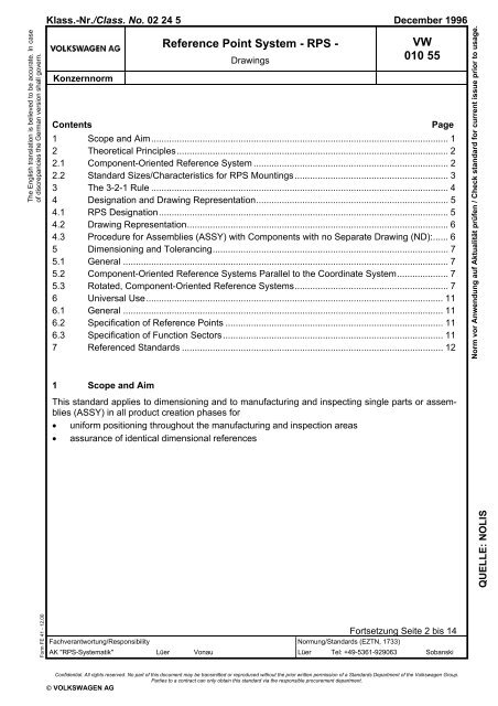
Klass.-Nr./Class. No. 02 24 5 December 1996<br />
Konzernnorm<br />
<strong>Reference</strong> <strong>Point</strong> <strong>System</strong> - <strong>RPS</strong> -<br />
Drawings<br />
<strong>VW</strong><br />
<strong>010</strong> <strong>55</strong><br />
Contents Page<br />
1 Scope and Aim.................................................................................................................... 1<br />
2 Theoretical Principles.......................................................................................................... 2<br />
2.1 Component-Oriented <strong>Reference</strong> <strong>System</strong> ............................................................................ 2<br />
2.2 Standard Sizes/Characteristics for <strong>RPS</strong> Mountings............................................................ 3<br />
3 The 3-2-1 Rule .................................................................................................................... 4<br />
4 Designation and Drawing Representation........................................................................... 5<br />
4.1 <strong>RPS</strong> Designation................................................................................................................. 5<br />
4.2 Drawing Representation......................................................................................................6<br />
4.3 Procedure for Assemblies (ASSY) with Components with no Separate Drawing (ND):...... 6<br />
5 Dimensioning and Tolerancing............................................................................................ 7<br />
5.1 General ............................................................................................................................... 7<br />
5.2 Component-Oriented <strong>Reference</strong> <strong>System</strong>s Parallel to the Coordinate <strong>System</strong>.................... 7<br />
5.3 Rotated, Component-Oriented <strong>Reference</strong> <strong>System</strong>s............................................................ 7<br />
6 Universal Use.................................................................................................................... 11<br />
6.1 General ............................................................................................................................. 11<br />
6.2 Specification of <strong>Reference</strong> <strong>Point</strong>s ..................................................................................... 11<br />
6.3 Specification of Function Sectors...................................................................................... 11<br />
7 <strong>Reference</strong>d Standards ...................................................................................................... 12<br />
1 Scope and Aim<br />
This standard applies to dimensioning and to manufacturing and inspecting single parts or assemblies<br />
(ASSY) in all product creation phases for<br />
• uniform positioning throughout the manufacturing and inspection areas<br />
• assurance of identical dimensional references<br />
Fortsetzung Seite 2 bis 14<br />
Fachverantwortung/Responsibility Normung/Standards (EZTN, 1733)<br />
AK "<strong>RPS</strong>-<strong>System</strong>atik" Lüer Vonau Lüer Tel: +49-5361-929063 Sobanski<br />
Confidential. All rights reserved. No part of this document may be transmitted or reproduced without the prior written permission of a Standards Department of the Volkswagen Group.<br />
Parties to a contract can only obtain this standard via the responsible procurement department.<br />
© VOLKSWAGEN AG<br />
Norm vor Anwendung auf Aktualität prüfen / Check standard for current issue prior to usage.<br />
QUELLE: NOLIS
Page 2<br />
<strong>VW</strong> <strong>010</strong> <strong>55</strong>: 1996-12<br />
2 Theoretical Principles<br />
2.1 Component-Oriented <strong>Reference</strong> <strong>System</strong><br />
One of the basic ideas forming the basis for the reference point system is the component-oriented<br />
coordinate system according to <strong>VW</strong> <strong>010</strong> 52.<br />
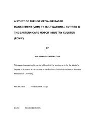
A vehicle is dimensioned by means of a global coordinate system (mathematical vehicle coordinate<br />
system), the origin of which is defined to be in the center at the level of the front axle of a vehicle<br />
(see <strong>VW</strong> <strong>010</strong> 59 Part 1; <strong>VW</strong> <strong>010</strong> 52 is the binding reference for the vehicle coordinate system),<br />
Figure 1.<br />
A Vertical plane S Longitudinal center plane D Horizontal plane<br />
Figure 1. Global coordinate system for vehicles<br />
Starting from the axes of this coordinate system, grid lines are spread out parallel to the axes.<br />
These grid lines, spaced 100 mm apart, theoretically penetrate the vehicle. These grid lines serve<br />
to find all points on the vehicle. In other words, they help to determine the position of each vehicle<br />
component. Dimensioning is also performed with the aid of these grid lines.<br />
The reference point system is based on a component-oriented reference system.<br />
The origin of the component reference system is defined by the intersection point of three reference<br />
planes. The reference planes are formed via the <strong>RPS</strong> main mountings defined on the component.<br />
When several parts are assembled, these parts are toleranced with respect to each other.<br />
After the parts are joined, the ASSY is described by a combined component-oriented reference<br />
system. This is formed<br />
by adoption of one of the existing reference systems or<br />
by forming a new reference system using the existing reference points.<br />
The specification of the new reference system depends on the function of the ASSY.
2.2 Standard Sizes/Characteristics for <strong>RPS</strong> Mountings<br />
Page 3<br />
<strong>VW</strong> <strong>010</strong> <strong>55</strong>: 1996-12<br />
Multiple-use location holes with high precision requirements must be adequately strong.<br />
In general, the standard sizes according to Table 1 and Table 2 shall be used. In case of holes in<br />
<strong>RPS</strong> surfaces, it must be ensured that the bearing surfaces are of adequate size and provide process<br />
assurance.<br />
The specified dimensions shall be projected – parallel to the axes – onto the component.<br />
Table 1. Recommended standard values<br />
For further standard sizes see <strong>VW</strong> <strong>010</strong> 77<br />
Designation Nominal dimension<br />
Tol. Graphical representation<br />
Location<br />
holes,<br />
pluggable<br />
Surfaces<br />
Edges<br />
Round hole see <strong>VW</strong> <strong>010</strong>77<br />
Square<br />
Rectangle<br />
Circle<br />
Edge<br />
length "a"<br />
10<br />
15<br />
20<br />
25<br />
6 x 20<br />
10 x 20<br />
15 x 20<br />
Ø 15<br />
Ø 20<br />
Ø 25<br />
Table 2. Recommended standard values<br />
For further standard sizes see <strong>VW</strong> <strong>010</strong> 78<br />
Location holes,<br />
pluggable<br />
Designation<br />
Long hole<br />
Long hole<br />
in angle<br />
position<br />
10<br />
20<br />
25<br />
Nominal dimension<br />
w x l<br />
see <strong>VW</strong> <strong>010</strong>78<br />
+1<br />
+1<br />
+1<br />
+1<br />
Tol. Graphical representation
Page 4<br />
<strong>VW</strong> <strong>010</strong> <strong>55</strong>: 1996-12<br />
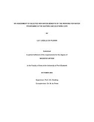
3 The 3-2-1 Rule<br />
Every rigid body possesses six degrees of freedom in three-dimensional space: three translational<br />
degrees parallel to the axes of a reference system and three rotatory degrees around the axes,<br />
Figure 2.<br />
Figure 2. The degrees of freedom in three-dimensional space<br />
In order to support a non-rotationally-symmetric body in a uniquely determinate manner, it must be<br />
fixed in all six possible directions of movement. The 3-2-1-rule provides for such unique fixing. It<br />
determines the following main-mounting distribution:<br />
E.g. 3 mountings in z direction<br />
2 mountings in y direction<br />
1 mounting in x direction<br />
Implementation of this rule is shown based on the following representation, Figure 3.<br />
Figure 3. Application of the 3-2-1 rule<br />
The three mountings in z direction restrict three degrees of freedom: translation in z direction and<br />
rotation around the x and y axes. The pin in the round hole prevents motion parallel to the axes in<br />
the x and y directions and, finally, the pin in the long hole prevents rotation around the z axis, Figure<br />
3.<br />
This rule applies equally to any other rigid component, even if its structure is much more complex.<br />
With a system of rigid bodies, the elements of which are interconnected by joints or guides, more<br />
than 6 degrees of freedom must be fixed using additional main mountings.<br />
For non-rigid components, additional support points must be defined for supporting the components<br />
according to <strong>RPS</strong> aspects.<br />
<strong>RPS</strong> 1 shall be the point that binds the most degrees of freedom.
4 Designation and Drawing Representation<br />
4.1 <strong>RPS</strong> Designation<br />
All <strong>RPS</strong> points must be included in the part drawing.<br />
The designation is subdivided as follows:<br />
• Main mounting points = Capitals<br />
→ H = Hole<br />
→ F = Surface<br />
→ T = Theoretical point<br />
is the mean of two support points<br />
• Support points = Small letters<br />
→ h = Hole<br />
→ f = Surface<br />
→ t = Theoretical point<br />
is the mean of two support points<br />
Page 5<br />
<strong>VW</strong> <strong>010</strong> <strong>55</strong>: 1996-12<br />
• Mounting types → Location holes/pins = Code letter H,h<br />
→ Surfaces/edges/ball/tip = Code letter F,f<br />
→ Theoretical point = Code letter T,t<br />
• Fixing directions = Small letters<br />
→ x, y, z for component-oriented reference systems parallel<br />
to the coordinate system<br />
→ a, b, c for rotated, component-oriented reference systems<br />
Examples of designation:<br />
Fixing direction<br />
Code letter for surface as main mounting<br />
Fixing directions<br />
Code letter for hole as main mounting<br />
Designation with numbering<br />
Fixing direction<br />
Code letter for surface as main mounting<br />
Designation with numbering<br />
Fixing direction<br />
Code letter for surface as support point<br />
Designation with numbering<br />
Numbering begins with the <strong>RPS</strong> 1 point for each single part and for each assembly.
Page 6<br />
<strong>VW</strong> <strong>010</strong> <strong>55</strong>: 1996-12<br />
4.2 Drawing Representation<br />
Drawing representation takes place according to the valid drawing guidelines.<br />
The <strong>RPS</strong> surfaces shall be identified by means of cross-hatching.<br />
If a part drawing does not exist yet, <strong>RPS</strong> Dimensions Sheet FE 515 1) shall be used.<br />
As soon as the part drawing exists, the specifications from the <strong>RPS</strong> Dimensions Sheet are adopted<br />
directly in the drawing or adopted in text macro NO-F23 2) . Administration of these specifications in<br />
the text macro is mandatory.<br />
4.3 Procedure for Assemblies (ASSY) with Components with no Separate Drawing (ND):<br />
The <strong>RPS</strong> points for components with no drawing (ND) must be identified by specifying the item<br />
number or part number.<br />
A drawing exists for part 1; ND for parts 2 and 3, Figure 4.<br />
A <strong>RPS</strong> 1 Hxy; <strong>RPS</strong> 1 Hxy for Item 3 S <strong>RPS</strong> 2 Hx only for Item 3<br />
D <strong>RPS</strong> 1 Hxy only for Item 2<br />
Fig. 4 ASSY with <strong>RPS</strong> points<br />
F <strong>RPS</strong> 2 Hy; <strong>RPS</strong> 2 Hy for Item 2<br />
Graphical representation, not adopted in drawing<br />
1) Stored in design data administration system under FEO 000 515<br />
2) Stored in design data administration system under NOF 000 023
5 Dimensioning and Tolerancing<br />
5.1 General<br />
Page 7<br />
<strong>VW</strong> <strong>010</strong> <strong>55</strong>: 1996-12<br />
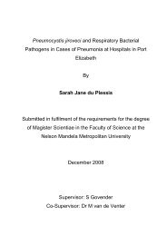
Dimensions and tolerances can be entered directly in the drawing or via the table, Figure 5.<br />
The starting point for dimensioning the components is generally the origin of the reference system.<br />
Form and functional dimensions with tolerances shall always be referenced to the origin of the reference<br />
system.<br />
Example: The holes within a hole group are dimensioned with respect to each other. The position<br />
of the hole group is dimensioned with respect to the reference planes.<br />
In the fixing direction, the main mountings are positioned without tolerance with respect to the vehicle<br />
coordinate system / reference system.<br />
The origin/reference point is shown in the drawing or table. If two or three fixing directions are<br />
bound at one point, tolerancing must be separated according to the hole or surface. In this case,<br />
the surface must be identified one line lower in the table. Here, the surface is set to zero in the tolerance<br />
zone. In the line in which the hole is set to zero, the tolerance zone for the surface shall be<br />
identified with a horizontal line, see the table in Figure 5.<br />
The support-point tolerances shall be defined according to the requirements.<br />
5.2 Component-Oriented <strong>Reference</strong> <strong>System</strong>s Parallel to the Coordinate <strong>System</strong><br />
The origin of the reference system is defined without tolerances in the global vehicle coordinate<br />
system by means of a translation, Figure 5<br />
5.3 Rotated, Component-Oriented <strong>Reference</strong> <strong>System</strong>s<br />
With rotated reference systems, the theoretical angles of rotation must be specified in <strong>RPS</strong> Dimensions<br />
Sheet FE 515 1) or in the drawing table text macro NO-F23 2) .<br />
If there are several angles of rotation, the angle specification and thus the sequence of rotations<br />
shall be obtained from the drawing. "See drawing" must be added to the table instead of the angle<br />
entry.<br />
The position of the reference point is determined by means of its x, y and z coordinates in the<br />
global vehicle coordinate system.<br />
Angles of rotation around the x, y and z axes are entered using mathematically positive or negative<br />
values. Positive angles are specified counterclockwise and negative angles clockwise.<br />
In the coordinate system, the horizontal axis is assigned an angle of zero.<br />
Nominal dimensions and tolerances are specified in a, b and c values in the <strong>RPS</strong> table.<br />
The fixing directions of the <strong>RPS</strong> points are specified as a, b and c values in the table and/or drawing,<br />
e.g. <strong>RPS</strong> 1 HabFc, Figure 6 and Figure 7.<br />
1), 2) see page 6
Page 8<br />
<strong>VW</strong> <strong>010</strong> <strong>55</strong>: 1996-12<br />
Feld<br />
Sect.<br />
<strong>RPS</strong><br />
F.-<br />
Pkt./<br />
Globale Koordinaten<br />
Global coordinates Aufnahmeart/ Bemerkung<br />
Mounting type/ note<br />
Bezugspunkt:<br />
x: 515 y: 275 z: 725<br />
<strong>Reference</strong> point:<br />
Theor. Drehwinkel um Achse:<br />
x: y: z:<br />
Theor. angle of rotat. around axis:<br />
Nennmasse/ Nominal sizes Toleranzen/ Tolerances<br />
Funct.<br />
AE AE AE<br />
point x y z<br />
x/a y/b z/c x/a y/b z/c<br />
1HxyFz 515 275 725 Hole Ø 14.5+0.2 0 0 0 0 0 – .<br />
. . . . . . . . Surface Ø 34.5+1 . . . ±1 ±1 0 .<br />
2Hx . . 520 365 725 Long hole 13+0.2 x 26+0.4 5 90 0 0 ±0.5 . .<br />
3F . . z 490 385 725 Surface 10+1 x 20+1 25 110 0 ±1 ±1 0 .<br />
4F . . z 600 380 725 Surface 10+1 x 20+1 85 105 0 ±1 ±1 0 .<br />
5F . . z 610 275 725 Surface 10+1 x 20+1 95 0 0 ±1 ±1 ±0.5 .<br />
a 1 595 350 725 Hole Ø 8+0.2 . . . . 0.2<br />
Fig. 5 Dimensioning with text macro NO–F23<br />
A if necessary
A <strong>Reference</strong> point S View R<br />
Page 9<br />
<strong>VW</strong> <strong>010</strong> <strong>55</strong>: 1996-12<br />
Feld<br />
Sect.<br />
<strong>RPS</strong><br />
F.-<br />
Pkt./<br />
Globale Koordinaten<br />
Global coordinates Aufnahmeart/ Bemerkung<br />
Mounting type/ note<br />
Bezugspunkt:<br />
x: 515 y: 275 z: 725<br />
<strong>Reference</strong> point:<br />
Theor. Drehwinkel um Achse:<br />
x: 0° y: 25° z: 0°<br />
Theor. angle of rotat. around axis:<br />
Nennmasse/ Nominal sizes Toleranzen/ Tolerances<br />
Funct.<br />
AE1 AE2 AE3<br />
point x y z<br />
x/a y/b z/c x/a y/b z/c<br />
1HabFc 515 275 725 Hole Ø 14.5+0.2 0 0 0 0 0 – .<br />
. . . . . . . . Surface Ø 34.5+1 . . . ±1 ±1 0 .<br />
2Ha . . 519.5 365 722.9 Long hole 13+0.2 x 26+0.4 5 90 0 0 ±0.5 . .<br />
3F . . c 492.3 385 735.6 Surface 10+1 x 20+1 25 110 0 ±1 ±1 0 .<br />
4F . . c 592 380 689.1 Surface 10+1 x 20+1 85 105 0 ±1 ±1 0 .<br />
5f . . c 601.1 275 684.8 Surface 10+1 x 20+1 95 0 0 ±1 ±1 ±0.5 .<br />
a 1 587.5 350 691.2 Hole Ø 8+0.2 . . . . 0.2<br />
Fig. 6 <strong>Reference</strong> point is formed directly via <strong>RPS</strong> main mountings.
Page 10<br />
<strong>VW</strong> <strong>010</strong> <strong>55</strong>: 1996-12<br />
A <strong>Reference</strong> point S View R<br />
Feld<br />
Sect.<br />
<strong>RPS</strong><br />
F.-<br />
Pkt./<br />
Globale Koordinaten<br />
Global coordinates Aufnahmeart/ Bemerkung<br />
Mounting type/ note<br />
Bezugspunkt:<br />
x: <strong>55</strong>0 y: 350 z: 650<br />
<strong>Reference</strong> point:<br />
Theor. Drehwinkel um Achse:<br />
x: 0° y: 25° z: 0°<br />
Theor. angle of rotat. around axis:<br />
Nennmasse/ Nominal sizes Toleranzen/ Tolerances<br />
Funct.<br />
AE1 AE2 AE3<br />
point x y z<br />
x/a y/b z/c x/a y/b z/c<br />
1HabFc <strong>55</strong>0 275 732.8 Hole Ø 14.5+0.2 35 75 75 0 0 – .<br />
. . . . . . . . Surface Ø 34.5+1 . . . ±1 ±1 0 .<br />
2Ha . . <strong>55</strong>4.5 365 730.6 Long hole 13+0.2 x 26+0.4 30 15 75 0 ±0.5 . .<br />
3F . . c 527.3 385 743.3 Surface 10+1 x 20+1 60 35 75 ±1 ±1 0 .<br />
4F . . c 627 380 696.8 Surface 10+1 x 20+1 50 30 75 ±1 ±1 0 .<br />
5f . . c 636.1 275 692.6 Surface 10+1 x 20+1 60 75 75 ±1 ±1 ±0.5 .<br />
a 1 622.5 350 699 Hole Ø 8+0.2 . . . . 0.2<br />
Fig. 7 <strong>Reference</strong> point is formed via <strong>RPS</strong> main mountings with defined distances
6 Universal Use<br />
6.1 General<br />
Page 11<br />
<strong>VW</strong> <strong>010</strong> <strong>55</strong>: 1996-12<br />
The purpose of the <strong>RPS</strong> is to provide process assurance/capability and repeat accuracy for the<br />
procedures in order to make them independent of setting work performed by the worker.<br />
The reference points must be used in all manufacturing, assembly, inspection and installation processes.<br />
In case of self-contained function sectors such as the side panel tank flap, a reference change in<br />
combination with functional dimensions to <strong>RPS</strong> planes is permissible.<br />
Prior to the specification of <strong>RPS</strong> points, it is absolutely necessary to define the functions of the single<br />
part and the relevant assemblies with their required functional tolerances.<br />
<strong>Reference</strong> points that were established at the beginning of a process must be kept for as long as<br />
possible. In order to avoid changes to arranged reference points, they are jointly defined – as early<br />
as possible in the design and development process – in consultation with all departments participating<br />
in the production process.<br />
<strong>Reference</strong> points must be positioned at stable areas of a component that will remain unchanged<br />
even in further development and/or production processes.<br />
<strong>Reference</strong> points on components that move relative to the body during driving operation can be<br />
considered according to the 3-2-1 rule only in the actual design position.<br />
The <strong>RPS</strong> points on components that are used several times in vehicles and thus have multiple references<br />
to the global coordinate system can be shown without a global coordinate reference in the<br />
technical drawing.<br />
The reference point system is equally oriented toward the production process, toward the function<br />
sectors and toward the strategic quality goals, e.g. audit, process capability.<br />
6.2 Specification of <strong>Reference</strong> <strong>Point</strong>s<br />
Parallelism to the coordinate system (holes and surfaces) must be observed when entering the<br />
reference points. In the case of rotated systems, parallelism to the reference planes must be observed.<br />
The <strong>RPS</strong> points must be produced in the tool sequence in which the greatest dimensional stability<br />
is attained.<br />
Whenever possible, reference points must be produced with a standardized shape (hole, surface),<br />
which must be defined in detail.<br />
If holes cannot be made in a component, surfaces or edges must be used to specify reference<br />
points.<br />
In the case of COP parts (transfer parts), the respective reference-point positions arise in the<br />
ASSY.<br />
6.3 Specification of Function Sectors<br />
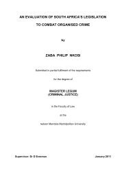
Use of the <strong>RPS</strong> on a complex portion of the vehicle such as the dashboard requires a structure that<br />
addresses the development and design engineering systems and includes all parts, single parts<br />
and assemblies.<br />
A function sector includes all components in the visible and covered areas that directly affect their<br />
surroundings with their function points.<br />
The specification of reference planes depends on the spatial and geometric position relationship of<br />
a component with its surroundings.<br />
The reference planes are identical for a function sector. In other words, components or component<br />
groups and the surroundings have the same starting basis, Figure 8.
Page 12<br />
<strong>VW</strong> <strong>010</strong> <strong>55</strong>: 1996-12<br />
A Dashboard ASSY function sector S Airbag function sector<br />
D Center-vent function sector F Air outlet vent function sector FS<br />
Fig. 8<br />
7 <strong>Reference</strong>d Standards<br />
<strong>VW</strong> <strong>010</strong> 52<br />
<strong>VW</strong> <strong>010</strong> 59 T1<br />
<strong>VW</strong> <strong>010</strong> 77<br />
<strong>VW</strong> <strong>010</strong> 78
Page 13<br />
<strong>VW</strong> <strong>010</strong> <strong>55</strong>: 1996-12
Page 14<br />
<strong>VW</strong> <strong>010</strong> <strong>55</strong>: 1996-12