Sedimentation and Clarification - Public Health
Sedimentation and Clarification - Public Health
Sedimentation and Clarification - Public Health

You also want an ePaper? Increase the reach of your titles
YUMPU automatically turns print PDFs into web optimized ePapers that Google loves.
<strong>Sedimentation</strong> <strong>and</strong> <strong>Clarification</strong><br />
<strong>Sedimentation</strong> is the next step in conventional filtration plants. (Direct filtration plants omit this<br />
step.) The purpose of sedimentation is to enhance the filtration process by removing particulates.<br />
<strong>Sedimentation</strong> is the process by which suspended particles are removed from the water by means<br />
of gravity or separation. In the sedimentation process, the water passes through a relatively quiet<br />
<strong>and</strong> still basin. In these conditions, the floc particles settle to the bottom of the basin, while<br />
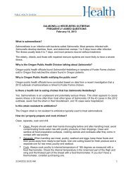
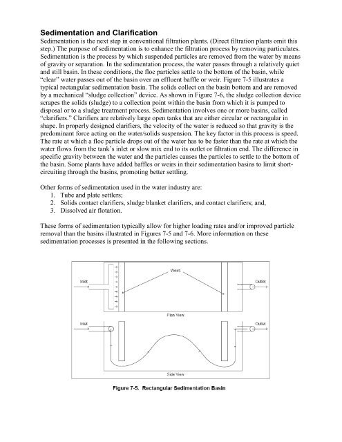
“clear” water passes out of the basin over an effluent baffle or weir. Figure 7-5 illustrates a<br />
typical rectangular sedimentation basin. The solids collect on the basin bottom <strong>and</strong> are removed<br />
by a mechanical “sludge collection” device. As shown in Figure 7-6, the sludge collection device<br />
scrapes the solids (sludge) to a collection point within the basin from which it is pumped to<br />
disposal or to a sludge treatment process. <strong>Sedimentation</strong> involves one or more basins, called<br />
“clarifiers.” Clarifiers are relatively large open tanks that are either circular or rectangular in<br />
shape. In properly designed clarifiers, the velocity of the water is reduced so that gravity is the<br />
predominant force acting on the water/solids suspension. The key factor in this process is speed.<br />
The rate at which a floc particle drops out of the water has to be faster than the rate at which the<br />
water flows from the tank’s inlet or slow mix end to its outlet or filtration end. The difference in<br />
specific gravity between the water <strong>and</strong> the particles causes the particles to settle to the bottom of<br />
the basin. Some plants have added baffles or weirs in their sedimentation basins to limit shortcircuiting<br />
through the basins, promoting better settling.<br />
Other forms of sedimentation used in the water industry are:<br />
1. Tube <strong>and</strong> plate settlers;<br />
2. Solids contact clarifiers, sludge blanket clarifiers, <strong>and</strong> contact clarifiers; <strong>and</strong>,<br />
3. Dissolved air flotation.<br />
These forms of sedimentation typically allow for higher loading rates <strong>and</strong>/or improved particle<br />
removal than the basins illustrated in Figures 7-5 <strong>and</strong> 7-6. More information on these<br />
sedimentation processes is presented in the following sections.
Pre-<strong>Sedimentation</strong><br />
Not all systems use pre-sedimentation, but pre-sedimentation is often used when raw water<br />
turbidity is high or highly variable. Pre-sedimentation basins range in size, depending on the<br />
flow, <strong>and</strong> the water is sometimes pre-treated with a coagulant <strong>and</strong>/or a polymer prior to entering<br />
the pre-sedimentation basin (AWWA, 1999). The addition of coagulants <strong>and</strong>/or polymers at this<br />
point in the treatment process could be helpful if a system needs to reduce the natural organic<br />
matter entering the plant. Natural organic matter is a disinfection byproduct precursor, <strong>and</strong> if a<br />
system has high organic matter (measured as total organic carbon, or TOC), then presedimentation<br />
could be beneficial for system compliance.<br />
Effect on Turbidity<br />
<strong>Sedimentation</strong> may remove suspended solids <strong>and</strong> reduce turbidity by about 50 to 90 percent,<br />
depending on the nature of the solids, the level of pretreatment provided, <strong>and</strong> the design of the<br />
clarifiers. Common values are in the 60 to 80 percent range (Hudson, 1981).
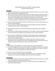
Tube <strong>and</strong> Plate Settlers<br />
Inclined tubes <strong>and</strong> plates can be used in sedimentation basins to allow greater loading rates. This<br />
technology relies on the<br />
theory of reduced-depth<br />
sedimentation: particles<br />
need only settle to the<br />
surface of the tube or<br />
plate below for removal<br />
from the process flow.<br />
Generally, a space of<br />
two inches is provided<br />
between tube walls or<br />
plates to maximize<br />
settling efficiency. The<br />
typical angle of<br />
inclination is about 60 degrees, so that settled solids slide down to the bottom of the basin.<br />
Figure 7-7 illustrates a plate settler used for high-rate sedimentation.
Solids Contact Clarifiers, Sludge Blanket Clarifiers, <strong>and</strong> Contact Clarifiers<br />
Solids contact clarifiers represent an entirely different approach to high-rate clarification. They<br />
consist of a basin similar to that used for a conventional clarifier, but with a sludge recycle<br />
system to promote development of a dense sludge blanket that captures floc. There are numerous<br />
types of solids contact units on the market in the United States. These units are all similar in<br />
design in that they combine solids contact mixing, flocculation, solids-water-separation, <strong>and</strong><br />
continuous removal of sludge in a single package-type basin. The recirculation rate of water <strong>and</strong><br />
solids in solids contact units is critical to the units’ effective operation. Too high a recirculation<br />
rate will cause the sludge blanket to lift <strong>and</strong> create increased loading to the filters.<br />
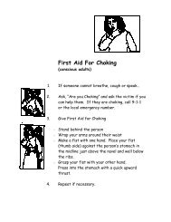
Accelator®<br />
An Accelator® solids contact clarifier is shown in Figure 7-8. Raw water enters the primary<br />
mixing <strong>and</strong> reaction zone, where it receives the coagulant chemical. Coagulation <strong>and</strong> flocculation<br />
begin in this chamber in the presence of previously formed floc particles. These particles provide<br />
the nucleus of new floc particles. The resulting solids precipitant is pumped up into a secondary<br />
mixing <strong>and</strong> reaction zone. More gentle mix energy in this chamber allows completion of the<br />
flocculation process <strong>and</strong> separation of the solids. The mixture of solids <strong>and</strong> water flows down a<br />
draft tube. The downward flow starts the solids particles on a path down the hood to the sludge<br />
blanket at the bottom of the basin. Clear water flows up at a constantly reducing velocity that<br />
allows small particles to settle out. Other manufacturers of solids contact units may have flow<br />
patterns different than the Accelator® flow pattern.<br />
Sludge Blanket Clarifiers<br />
Sludge blanket clarifiers are a variation of solids contact units in which coagulated water flows<br />
up through a blanket of previously formed solids. As the small, coagulated particles enter the<br />
sludge blanket, contact with other particles in the blanket causes flocculation to occur. The floc<br />
grows in size <strong>and</strong> becomes part of the blanket. A blanket depth of several feet is required for<br />
efficient clarification (AWWA <strong>and</strong> ASCE, 1998).
Contact Clarifiers<br />
Contact clarifiers (sometimes referred to as contact adsorption clarifiers) are designed to provide<br />
flocculation <strong>and</strong> clarification in a single process. These clarifiers consist of a basin filled with<br />
adsorption media, generally plastic or rock about the size of pea gravel. As water passes through<br />
the media, hydraulic mixing promotes flocculation <strong>and</strong> the flocculated particles adhere to the<br />
surface of the media particles. The media is cleaned periodically using an air, or air <strong>and</strong> water,<br />
backwash process to remove the solids.<br />
Dissolved Air Flotation<br />
Dissolved air flotation clarifiers bubble air into the flocculated water <strong>and</strong> cause the floc particles<br />
to float to the surface. Dissolved air flotation clarification allows for loading rates up to 10 times<br />
that of conventional<br />
clarifiers (AWWA <strong>and</strong><br />
ASCE, 1998). Dissolved air<br />
flotation consists of<br />
saturating a sidestream with<br />
air at high pressure <strong>and</strong> then<br />
injecting it into a flotation<br />
tank to mix with incoming<br />
water. As the side-stream<br />
enters the flotation tank, the<br />
pressure drop releases the<br />
dissolved air. The air<br />
bubbles then rise, attaching<br />
to floc particles <strong>and</strong><br />
creating a layer of sludge at the surface of the tank. The clarified water is collected near the<br />
bottom of the tank.
Optimization of the <strong>Sedimentation</strong> <strong>and</strong> <strong>Clarification</strong> Process<br />
Optimization of the clarification process will minimize solids loading on the filters <strong>and</strong> will<br />
contribute to enhanced filter performance <strong>and</strong> better overall treated water quality.A water system<br />
should consider the following items when evaluating sedimentation basins:<br />
1. Conducting a tracer study in the sedimentation basin. Often, very simple design changes<br />
can be made to improve sedimentation basin performance. For information on tracer<br />
studies, see the LT1ESWTR Disinfection Profiling <strong>and</strong> Benchmarking Technical<br />
Guidance Manual (EPA, 2003).<br />
2. Is sludge collection <strong>and</strong> removal adequate? Inadequate sludge collection <strong>and</strong> removal can<br />
cause particles to become re-suspended in water or upset circulation. Systems should<br />
disrupt the sludge blanket as little as possible. Sludge draw-off rates can affect the sludge<br />
blanket. Sludge draw-off procedures should be checked periodically, making sure sludge<br />
levels are low <strong>and</strong> sludge should be wasted if necessary. Sludge pumping lines should be<br />
inspected routinely to ensure that they are not becoming plugged. These lines should also<br />
be flushed occasionally to prevent the buildup of solids.<br />
3. Do basin inlet <strong>and</strong> outlet conditions prevent the breakup of formed floc particles? Settling<br />
basin inlets are often responsible for creating turbulence that can break up floc.<br />
Improperly designed outlets are also often responsible for the breakup of floc. Finger<br />
launders (small troughs with V–notch weir openings that collect water uniformly over a<br />
large area of a basin) can be used to decrease the chance of floc breakup.<br />
4. Is the floc the correct size <strong>and</strong> density? Poorly formed floc is characterized by small or<br />
loosely held particles that do not settle properly <strong>and</strong> are carried out of the settling basin.<br />
Such floc may be the result of inadequate rapid mixing, improper coagulant dosages, or<br />
improper flocculation. Systems should look to previous steps in the treatment train to<br />
solve this problem.<br />
5. Is the basin subject to short-circuiting? If the basin is not properly designed, water<br />
bypasses the normal flow path through the basin <strong>and</strong> reaches the outlet in less than the<br />
normal detention time. Causes of shortcircuiting may include poor influent baffling or<br />
improperly placed collection troughs. If the influent enters the basin <strong>and</strong> hits a solid<br />
baffle, strong currents may result. A perforated baffle may distribute inlet water without<br />
causing strong currents. Tube or plate settlers may also improve efficiency, especially if<br />
flows have increased beyond original design conditions. The installation of tube settlers<br />
can sometimes double a basin’s original settling capacity.<br />
6. Are basins located outside <strong>and</strong> subject to windy conditions? Wind can create currents in<br />
open basins that can cause short-circuiting or disturb the floc. If wind poses a problem,<br />
installing barriers may reduce the effect <strong>and</strong> keep debris out of the unit.<br />
7. Are basins subject to algal growth? Although primarily a problem in open, outdoor<br />
basins, algae can also grow as a result of window placement around indoor basins. Algae<br />
should be removed regularly to avoid buildup.<br />
8. Is the sludge blanket in SCUs maintained properly? Operators should be able to measure<br />
the sludge depth <strong>and</strong> percent solids to ensure the sludge blanket is within the<br />
manufacturer’s recommendations. A timing device to ensure consistent blanket quality<br />
characteristics should control sludge removal rates <strong>and</strong> schedule.<br />
9. Is the recirculation rate for SCUs within the manufacturer’s recommendations? Various<br />
designs have different recirculation rates <strong>and</strong> flow patterns. Systems should refer to the<br />
manufacturer’s operation manual.
Equations for Determining Basin Volumes