
Create successful ePaper yourself
Turn your PDF publications into a flip-book with our unique Google optimized e-Paper software.
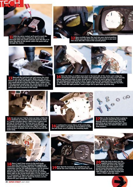
11 With the wires routed, we’ll need to mark the<br />
tach posts using a paint pen. Be sure to be<br />
thorough with your paint coverage since the idea is to<br />
leave two dots on the plastic where the posts will go<br />
through the cluster.<br />
Now pull the tach back out and remove the cover<br />
13 so you can drill your spots. Make sure the circuit<br />
board is out of the way before you start drilling! I used a<br />
very small drill bit to start the holes since I wasn’t sure<br />
if the placement would clear the circuit board or not. It’s<br />
a good idea for you to do the same since there is some<br />
guess-and-check involved in this install.<br />
As you can see I had to clock my holes a little bit<br />
15 clockwise to clear the circuit board but in doing<br />
so I found a location where I didn’t have to pierce any<br />
portion of circuit board. You may have to drill your<br />
board but just make sure you aren’t going through any<br />
metal portion and you’re in the clear. Next I cut away<br />
some sections of plastic that were interfering with the<br />
tach’s body.<br />
Since I won’t have access to the bolt heads<br />
18once the tach is in, I mounted the supplied eye<br />
connectors before installing the tach. I installed three<br />
connectors, one for 12v switched power, one for ground<br />
and one for the Ignitor signal that drives the tach.<br />
Honda makes the power and ground easy by marking<br />
them right on the circuit board with a (+) for power and<br />
a (-) for ground. To figure out which terminal is for the<br />
Ignitor signal make sure to check the factory service<br />
manual for your vehicle like I did.<br />
70 SUPER STREET JULY 2010<br />
Now carefully lower the tach into your desired position.<br />
12 Make sure you don’t move the tach around as you want<br />
two clean dots like I have in the second picture.<br />
Once the holes are drilled move back to the back side of the cluster and realign the<br />
14 circuit board. Check where the holes come through and make sure they aren’t directly<br />
below any metal portions of your circuit board – if they are you’re going to have to move<br />
the mounting points until they’re clear. As you can see in the second picture I’m pointing<br />
to where the upper hole lined up, it was right on the circuit and I had to relocate my holes.<br />
Once I found the right position I used a larger bit to open them up all the way.<br />
I continued to remove three of the protruding<br />
16pegs where I am going to run hardware so that<br />
the bolt heads aren’t limiting the mounting depth.<br />
Now that the terminals are installed we can<br />
19throw the cover backing on and mount the tach.<br />
Here is the hardware that is going to<br />
17be used to connect the tach wiring<br />
directly into the circuit board. You can<br />
pick these up at most any hardware store:<br />
(3) 4mmX7 nuts, (3) 4mmX7 bolts and (3)<br />
4mm washers.<br />
With the tach in place use the<br />
20supplied washers and 7mm lock<br />
nuts to secure the tach to the cluster.<br />
I had to leave the lower corner of the<br />
circuit board disconnected to secure<br />
the lower stud, but the top stud went<br />
right through an already existing hole<br />
– score! (That’s what she said.)