Mechanical Components.pdf - Ken Gilbert
Mechanical Components.pdf - Ken Gilbert
Mechanical Components.pdf - Ken Gilbert

Create successful ePaper yourself
Turn your PDF publications into a flip-book with our unique Google optimized e-Paper software.
4-1 [S100] SPECIFICATION AND SERVICE DATA<br />
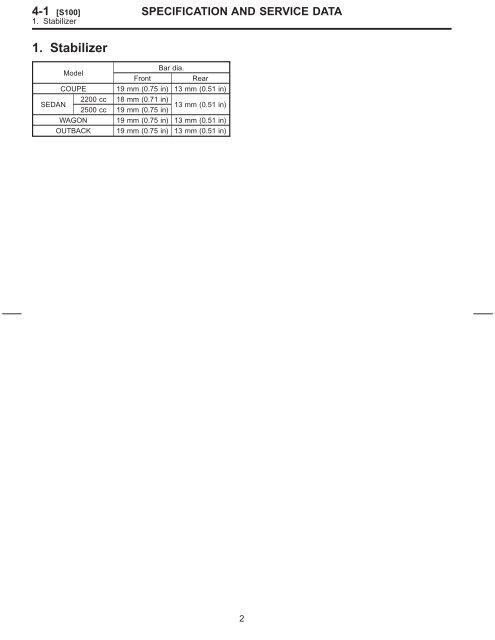
1. Stabilizer<br />
1. Stabilizer<br />
Model<br />
Front<br />
Bar dia.<br />
Rear<br />
COUPE 19 mm (0.75 in) 13 mm (0.51 in)<br />
SEDAN<br />
2200 cc<br />
2500 cc<br />
18 mm (0.71 in)<br />
19 mm (0.75 in)<br />
13 mm (0.51 in)<br />
WAGON 19 mm (0.75 in) 13 mm (0.51 in)<br />
OUTBACK 19 mm (0.75 in) 13 mm (0.51 in)<br />
2
2. Wheel Alignment<br />
Front<br />
Rear<br />
2200 cc 2500 cc<br />
Sedan,<br />
Coupe<br />
Wagon OUTBACK Coupe Sedan<br />
Camber<br />
(tolerance: ±0°30′)<br />
0° 0° 0° −0°25′ −0°25′<br />
Caster<br />
(common difference: ±1°)<br />
3° 3° 3°<br />
0±3 mm(0±0.12 in)<br />
3°05′ 3°05′<br />
Toe-in<br />
Each toe-in angle: −0°09′ [when toe-in is −3 mm (−0.12 in)]<br />
Each toe-out angle: 0°09′ [when toe-out is 3 mm (0.12 in)]<br />
Kingpin angle 14° 14° 14° 14° 14°<br />
Wheel arch height<br />
[tolerance: +12 / −24 mm ( +0.47 / − 0.94 in)]<br />
Camber<br />
(tolerance: ±0°45′)<br />
391 mm<br />
(15.39 in)<br />
391 mm<br />
(15.39 in)<br />
394 mm<br />
(15.51 in)<br />
371 mm<br />
(14.61 in)<br />
371 mm<br />
(14.61 in)<br />
−0°55′ −0°55′ −0°55′ −1°10′ −1°10′<br />
Toe-in 0±3 mm(0±0.12 in) Each toe-in angle: 0°±18′<br />
Wheel arch height<br />
[tolerance: +12 / −24 mm ( +0.47 / − 0.94 in)]<br />
Thrust angle<br />
(tolerance: 0°±20′)<br />
379 mm<br />
(14.92 in)<br />
NOTE:<br />
Front and rear toe-ins and front camber can be<br />
adjusted. If toe-in or camber tolerance exceeds<br />
specifications, adjust toe-in and camber to the<br />
specification.<br />
The other items indicated in the specification<br />
table cannot be adjusted. If the other items<br />
exceeds specifications, check suspension parts<br />
and connections for deformities; and replace with<br />
new ones as required.<br />
SPECIFICATION AND SERVICE DATA<br />
B4M2250A<br />
379 mm<br />
(14.92 in)<br />
386 mm<br />
(15.20 in)<br />
363 mm<br />
(14.29 in)<br />
363 mm<br />
(14.29 in)<br />
0° 0° 0° 0° 0°<br />
3<br />
[S200] 4-1<br />
2. Wheel Alignment
4-1 [C100] COMPONENT PARTS<br />
1. Front Suspension<br />
1. Front Suspension<br />
(1) Crossmember<br />
(2) Bolt ASSY<br />
(3) Housing<br />
(4) Washer<br />
(5) Stop rubber (Rear)<br />
(6) Rear bushing<br />
(7) Stop rubber (Front)<br />
(8) Ball joint<br />
(9) Transverse link<br />
(10) Cotter pin<br />
(11) Front bushing<br />
(12) Stabilizer link<br />
(13) Clamp<br />
(14) Bushing<br />
(15) Stabilizer<br />
(16) Jack-up plate (Except 2500 cc<br />
MT model)<br />
(17) Dust seal<br />
(18) Strut mount<br />
(19) Spacer<br />
(20) Upper spring seat<br />
(21) Rubber seat<br />
(22) Dust cover<br />
(23) Helper<br />
(24) Coil spring<br />
(25) Damper strut<br />
(26) Adjusting bolt<br />
(27) Castle nut<br />
(28) Self-locking nut<br />
(29) Dynamic damper (2500 cc MT<br />
model)<br />
4<br />
(30) Jack-up plate (2500 cc MT<br />
model)<br />
H4M1287A
Tightening torque: N·m (kg-m, ft-lb)<br />
T1: 18±5 (1.8±0.5, 13.0±3.6)<br />
T2: 20±6 (2.0±0.6, 14.5±4.3)<br />
T3: 25±4 (2.5±0.4, 18.1±2.9)<br />
T4: 29±5 (3.0±0.5, 21.7±3.6)<br />
T5: 39 (4, 29)<br />
T6: 44±6 (4.5±0.6, 32.5±4.3)<br />
T7: 49±10 (5.0±1.0, 36±7)<br />
T8: 54±5 (5.5±0.5, 39.8±3.6)<br />
T9: 98±15 (10.0±1.5, 72±11)<br />
T10: 152±20 (15.5±2.0, 112±14)<br />
T11: 186±10 (19.0±1.0, 137±7)<br />
T12: 245±49 (25.0±5.0, 181±36)<br />
COMPONENT PARTS<br />
5<br />
[C100] 4-1<br />
1. Front Suspension
4-1 [C200] COMPONENT PARTS<br />
2. Rear Suspension<br />
2. Rear Suspension<br />
(1) Stabilizer<br />
(2) Stabilizer bracket<br />
(3) Stabilizer bushing<br />
(4) Clamp<br />
(5) Floating bushing<br />
(6) Stopper<br />
(7) Stabilizer link<br />
(8) Rear lateral link<br />
(9) Bushing (C)<br />
(10) Bushing (A)<br />
(11) Front lateral link<br />
(12) Bushing (B)<br />
(13) Trailing link rear bushing<br />
(14) Trailing link<br />
(15) Trailing link front bushing<br />
(16) Trailing link bracket<br />
(17) Cap<br />
(18) Washer<br />
(19) Crossmember<br />
(20) Cap<br />
(21) Strut mount<br />
(22) Spring seat<br />
(23) Rubber seat upper<br />
(24) Dust cover<br />
(25) Coil spring<br />
(26) Helper<br />
(27) Rubber seat lower<br />
(28) Damper strut<br />
(29) Self-locking nut<br />
6<br />
H4M1273A<br />
Tightening torque: N·m (kg-m, ft-lb)<br />
T1: 20±6 (2.0±0.6, 14.5±4.3)<br />
T2: 25±7 (2.5±0.7, 18.1±5.1)<br />
T3: 44±6 (4.5±0.6, 32.5±4.3)<br />
T4: 59±10 (6.0±1.0, 43±7)<br />
T5: 98±15 (10.0±1.5, 72±11)<br />
T6: 98±20 (10.0±2.0, 72±14)<br />
T7: 113±15 (11.5±1.5, 83±11)<br />
T8: 127±20 (13.0±2.0, 94±14)<br />
T9: 137±20 (14.0±2.0, 101±14)<br />
T10: 196 +39 / −10 (20.0 +4.0 / −1.0,<br />
145 +29 / −7 )
1. On-car Services<br />
A: WHEEL ALIGNMENT<br />
PROCEDURES<br />
Check, adjust and/or measure wheel alignment in<br />
accordance with procedures indicated in figure.<br />
SERVICE PROCEDURE<br />
7<br />
[W1A0] 4-1<br />
1. On-car Services<br />
B4M1088A
4-1 [W1B1] SERVICE PROCEDURE<br />
1. On-car Services<br />
B: INSPECTION AND ADJUSTMENT<br />
1. WHEEL ARCH HEIGHT (FRONT AND<br />
REAR)<br />
1) Adjust tire pressure to specifications.<br />
2) Set vehicle under “curb weight” conditions.<br />
(Empty luggage compartment, install spare tire,<br />
jack, service tools, and top up fuel tank.)<br />
3) Set steering wheel in a wheel-forward position.<br />
4) Suspend thread from wheel arch (point “A” in<br />
figure) to determine a point directly above center of<br />
spindle.<br />
5) Measure distance between measuring point “A”<br />
and center of spindle.<br />
2200 cc<br />
2500 cc<br />
Vehicles<br />
Front<br />
Specified wheel arch height<br />
Rear<br />
Coupe, Sedan 391 +12 / −24 mm (15.39 +0.47 / −0.94 in) 379 +12 / −24 mm (14.92 +0.47 / −0.94 in)<br />
Wagon 391 +12 / −24 mm (15.39 +0.47 / −0.94 in) 379 +12 / −24 mm (14.92 +0.47 / −0.94 in)<br />
OUTBACK 394 +12 / −24 mm (15.51 +0.47 / −0.94 in) 386 +12 / −24 mm (15.20 +0.47 / −0.94 in)<br />
Coupe 371 +12 / −24 mm (14.61 +0.47 / −0.94 in) 363 +12 / −24 mm (14.29 +0.47 / −0.94 in)<br />
Sedan 371 +12 / −24 mm (14.61 +0.47 / −0.94 in) 363 +12 / −24 mm (14.29 +0.47 / −0.94 in)<br />
8<br />
G4M0479
2. CAMBER (FRONT AND REAR)<br />
Inspection<br />
1) Place front wheel on turning radius gauge.<br />
Make sure ground contacting surfaces of front and<br />
rear wheels are set at the same height.<br />
2) Set ST into the center of the wheel, and then<br />
install the wheel alignment gauge.<br />
ST 927380000 ADAPTER<br />
B4M0567A<br />
NOTE:<br />
Refer to the “SPECIFICATIONS AND SERVICE<br />
DATA” for the camber values. <br />
Front camber adjustment<br />
1) Loosen two self-locking nuts located at lower<br />
front portion of strut.<br />
CAUTION:<br />
When adjusting bolt needs to be loosened or<br />
tightened, hold its head with a wrench and turn<br />
self-locking nut.<br />
Discard loosened self-locking nut and<br />
replace with a new one.<br />
Camber is<br />
increased.<br />
Camber is<br />
decreased.<br />
2) Turn camber adjusting bolt so that camber is<br />
set at the specification.<br />
NOTE:<br />
Moving the adjusting bolt by one scale graduation<br />
changes camber by approximately 0°10′.<br />
Left side Right side<br />
B4M0190<br />
B4M0350<br />
SERVICE PROCEDURE<br />
Rotate counterclockwise.<br />
Rotate clockwise.<br />
B4M0350<br />
B4M0190<br />
S4M0300A<br />
Rotate clockwise.<br />
Rotate counterclockwise.<br />
3) Tighten the two self-locking nuts. Tightening torque:<br />
152±20 N·m (15.5±2.0 kg-m, 112±14 ft-lb)<br />
9<br />
[W1B2] 4-1<br />
1. On-car Services
4-1 [W1B3] SERVICE PROCEDURE<br />
1. On-car Services<br />
3. CASTER (FRONT)<br />
Inspection<br />
1) Place front wheel on turning radius gauge.<br />
Make sure ground contacting surfaces of front and<br />
rear wheels are set at the same height.<br />
2) Set ST into the center of the wheel, and then<br />
install the wheel alignment gauge.<br />
ST 927380000 ADAPTER<br />
NOTE:<br />
Refer to the “SPECIFICATIONS AND SERVICE<br />
DATA” for the caster value. <br />
B4M0567A<br />
4. FRONT WHEEL TOE-IN<br />
Inspection<br />
1) Using a toe gauge, measure front wheel toe-in.<br />
Toe-in: 0±3 mm(0±0.12 in)<br />
2) Mark rear sides of left and right tires at height<br />
corresponding to center of spindles and measure<br />
distance “B” between marks.<br />
3) Move vehicle forward so that marks line up with<br />
front sides at height corresponding to center of<br />
spindles.<br />
4) Measure distance “A” between left and right<br />
marks. Toe-in can then be obtained by the following<br />
equation:<br />
B − A = Toe-in<br />
M4A0059<br />
10<br />
Adjustment<br />
1) Loosen the left and right side steering tie-rods<br />
lock nuts.<br />
2) Turn the left and right tie rods equal amounts<br />
until the toe-in is at the specification.<br />
Both the left and right tie-rods are right-hand<br />
threaded. To increase toe-in, turn both tie-rods<br />
clockwise equal amounts (as viewed from the<br />
inside of the vehicle).<br />
3) Tighten tie-rod lock nut.<br />
G4M0482<br />
Tightening torque:<br />
83±5 N·m (8.5±0.5 kg-m, 61.5±3.6 ft-lb)<br />
CAUTION:<br />
Correct tie-rod boot, if it is twisted.<br />
NOTE:<br />
Check the left and right wheel steering angle is<br />
within specifications.
5. REAR WHEEL TOE-IN<br />
Inspection<br />
1) Using a toe-in gauge, measure rear wheel toein.<br />
Toe-in: 0±3 mm(0±0.12 in)<br />
2) Mark rear sides of left and right tires at height<br />
corresponding to center of spindles and measure<br />
distance “B” between marks.<br />
3) Move vehicle forward so that marks line up with<br />
front sides at height corresponding to center of<br />
spindles.<br />
4) Measure distance “A” between left and right<br />
marks. Toe-in can then be obtained by the following<br />
equation:<br />
B − A = Toe-in<br />
Toe-in is<br />
increased.<br />
Toe-in is<br />
decreased.<br />
M4A0059<br />
Adjustment<br />
1) Loosen self-locking nut on inner side of rear<br />
lateral link.<br />
CAUTION:<br />
When loosening or tightening adjusting bolt,<br />
hold bolt head and turn self-locking nut.<br />
Discard loosened self-locking nut and<br />
replace with a new one.<br />
G4M0486<br />
2) Turn adjusting bolt head until toe-in is at the<br />
specification.<br />
NOTE:<br />
When left and right wheels are adjusted for toe-in<br />
at the same time, the movement of one scale<br />
graduation changes toe-in by approximately 3 mm<br />
(0.12 in).<br />
Left side Right side<br />
B4M0192<br />
B4M0352<br />
3) Tighten self-locking nut.<br />
Tightening torque:<br />
98±15 N·m (10±1.5 kg-m, 72±11 ft-lb)<br />
SERVICE PROCEDURE<br />
Rotate clockwise.<br />
Rotate counterclockwise.<br />
11<br />
B4M0352<br />
B4M0192<br />
[W1B5] 4-1<br />
1. On-car Services<br />
Rotate counterclockwise.<br />
Rotate clockwise.
4-1 [W1B6] SERVICE PROCEDURE<br />
1. On-car Services<br />
6. THRUST ANGLE<br />
Inspection<br />
1) Position vehicle on a level surface.<br />
2) Move vehicle 3 to 4 meters directly forward.<br />
3) Determine locus of both front and rear axles.<br />
4) Measure distance “L” between center line of<br />
loci of the axles.<br />
Thrust angle:<br />
Less than 20′ when “L” is equal to or<br />
less than 15 mm (0.59 in).<br />
G4M0488<br />
Adjustment<br />
1) Make thrust angle adjustments by turning toe-in<br />
adjusting bolts of rear suspension equally in the<br />
same direction.<br />
2) When one rear wheel is adjusted in a toe-in<br />
direction, adjust the other rear wheel equally in<br />
toe-out direction, in order to make thrust angle<br />
adjustment.<br />
3) When left and right adjusting bolts are turned<br />
incrementally by one graduation in the same<br />
direction, the thrust angle of the AWD model will<br />
change approximately 10′ [“L” is almost equal to<br />
7.5 mm (0.295 in)].<br />
Thrust angle:<br />
0°±20′<br />
12<br />
NOTE:<br />
Thrust angle refers to a mean value of left and right<br />
rear wheel toe angles in relation to vehicle body<br />
center line. Vehicle is driven straight in the thrust<br />
angle direction while swinging in the oblique direction<br />
depending on the degree of the mean thrust<br />
angle.<br />
B4M0193A<br />
B4M0194A<br />
Thrust angle: r<br />
r=(α − β) /2<br />
α: Right rear wheel toe angle<br />
β: Left rear wheel toe angle<br />
NOTE:<br />
Here, use only positive toe-in values from each<br />
wheel to substitute for α and β in the equation.<br />
7. STEERING ANGLE<br />
Inspection<br />
1) Place vehicle on a turning radius gauge.<br />
2) While depressing brake pedal, turn steering<br />
wheel fully to the left and right. With steering wheel<br />
held at each fully turned position, measure both the<br />
inner and outer wheel steering angle.<br />
Steering angle:<br />
Inner wheel 37.4°±1.5°<br />
Outer wheel 32.5°±1.5°
Adjustment<br />
Turn tie-rod to adjust steering angle of both inner<br />
and outer wheels.<br />
CAUTION:<br />
Check toe-in.<br />
Correct boot if it is twisted.<br />
SERVICE PROCEDURE<br />
G4M0482<br />
13<br />
[W1B7] 4-1<br />
1. On-car Services
4-1 [W2A0] SERVICE PROCEDURE<br />
2. Front Transverse Link<br />
2. Front Transverse Link<br />
A: REMOVAL<br />
(1) Front crossmember<br />
(2) Transverse link<br />
(3) Stabilizer link<br />
(4) Front stabilizer<br />
(5) Self-locking nut<br />
1) Disconnect stabilizer link from transverse link.<br />
2) Remove bolt securing ball joint of transverse<br />
link to housing.<br />
G4M0491<br />
3) Remove nuts (do not remove bolts.) securing<br />
transverse link to crossmember.<br />
14<br />
B4M1084A<br />
Tightening torque: N·m (kg-m, ft-lb)<br />
T1: 29±5 (3.0±0.5, 21.7±3.6)<br />
T2: 44±6 (4.5±0.6, 32.5±4.3)<br />
T3: 98±15 (10.0±1.5, 72±11)<br />
T4: 186±10 (19.0±1.0, 137±7)<br />
T5: 245±49 (25.0±5.0, 181±36)<br />
4) Remove two bolts securing bushing bracket of<br />
transverse link to car body at rear bushing location.<br />
5) Extract ball joint from housing.<br />
G4M0492
6) Remove bolts securing transverse link to crossmember<br />
and extract transverse link from crossmember.<br />
B: DISASSEMBLY<br />
1. FRONT BUSHING<br />
G4M0493<br />
Using ST, press front bushing out of place.<br />
ST 927680000 INSTALLER & REMOVER SET<br />
G4M0494<br />
2. REAR BUSHING<br />
1) Scribe an aligning mark on transverse link and<br />
rear bushing.<br />
2) Loosen nut and remove rear bushing.<br />
SERVICE PROCEDURE<br />
G4M0495<br />
15<br />
C: INSPECTION<br />
1) Check transverse link for wear, damage and<br />
cracks, and correct or replace if defective.<br />
2) Check bushings for cracks, fatigue or damage.<br />
3) Check rear bushing for oil leaks.<br />
D: ASSEMBLY<br />
1. FRONT BUSHING<br />
[W2D2] 4-1<br />
2. Front Transverse Link<br />
To reassemble, reverse disassembly procedures.<br />
CAUTION:<br />
Install front bushing in correct direction, as<br />
shown in figure.<br />
G4M0496<br />
2. REAR BUSHING<br />
1) Install rear bushing to transverse link and align<br />
aligning marks scribed on the two.<br />
2) Tighten self-locking nut.<br />
CAUTION:<br />
Discard loosened self-locking nut and<br />
replace with a new one.<br />
While holding rear bushing so as not to<br />
change position of aligning marks, tighten selflocking<br />
nut.<br />
Tightening torque:<br />
186±10 N·m (19.0±1.0 kg-m, 137±7 ft-lb)
4-1 [W2E0] SERVICE PROCEDURE<br />
2. Front Transverse Link<br />
E: INSTALLATION<br />
1) Temporarily tighten the two bolts used to secure<br />
rear bushing of the transverse link to body.<br />
NOTE:<br />
These bolts should be tightened to such an extent<br />
that they can still move back and forth in the oblong<br />
shaped hole in the bracket (which holds the bushing).<br />
2) Install bolts used to connect transverse link to<br />
crossmember and temporarily tighten with nuts.<br />
CAUTION:<br />
Discard loosened self-locking nut and replace<br />
with a new one.<br />
3) Insert ball joint into housing.<br />
4) Connect stabilizer link to transverse link, and<br />
temporarily tighten bolts.<br />
CAUTION:<br />
Discard loosened self-locking nut and replace<br />
with a new one.<br />
G4M0497<br />
5) Tighten the following points in the order shown<br />
afterward when wheels are in full contact with the<br />
ground and vehicle is curb weight.<br />
(1) Transverse link and stabilizer<br />
Tightening torque:<br />
29±5 N·m (3.0±0.5 kg-m, 21.7±3.6 ft-lb)<br />
(2) Transverse link and crossmember<br />
Tightening torque:<br />
98±15 N·m (10.0±1.5 kg-m, 72±11 ft-lb)<br />
(3) Transverse link rear bushing and body<br />
Tightening torque:<br />
245±49 N·m (25±5 kg-m, 181±36 ft-lb)<br />
16<br />
NOTE:<br />
Move rear bushing back and forth until transverse<br />
link- to-rear bushing clearance is established<br />
(as indicated in figure.) before tightening.<br />
Check wheel alignment and adjust if necessary.<br />
G4M0928
3. Front Ball Joint<br />
A: REMOVAL<br />
1) Remove the wheels.<br />
2) Pull out the cotter pin from the ball stud, remove<br />
the castle nut, and extract the ball stud from the<br />
transverse link.<br />
3) Remove the bolt securing the ball joint to the<br />
housing.<br />
4) Extract the ball joint from the housing.<br />
B: INSPECTION<br />
G4M0499<br />
1) Measure play of ball joint by the following procedures.<br />
Replace with a new one when the play<br />
exceeds the specified value.<br />
(1) With 686 N (70 kg, 154 lb) loaded in the<br />
direction shown in the figure, measure dimension<br />
1.<br />
G4M0500<br />
(2) With 686 N (70 kg, 154 lb) loaded in the<br />
opposite direction shown in the figure, measure<br />
dimension 2.<br />
SERVICE PROCEDURE<br />
G4M0501<br />
17<br />
(3) Calculate plays from the following formula.<br />
S= 2 − 1<br />
(4) When plays is larger than the following<br />
value, replace with a new one.<br />
FRONT BALL JOINT<br />
Specified play for replacement: S<br />
Less than 0.3 mm (0.012 in)<br />
2) When play is smaller than the specified value,<br />
visually inspect the dust cover.<br />
3) The ball joint and cover that have been<br />
removed must be checked for wear, damage or<br />
cracks, and any defective part must be replaced.<br />
4) If the dust cover is damaged, replace with the<br />
new ball joint.<br />
C: INSTALLATION<br />
[W3C0] 4-1<br />
3. Front Ball Joint<br />
1) Install ball joint onto housing.<br />
Tightening torque (Bolt):<br />
49 N·m (5.0 kg-m, 36 ft-lb)<br />
CAUTION:<br />
Do not apply grease to tapered portion of ball<br />
stud.<br />
2) Connect ball joint to transverse link.<br />
Tightening torque (Castle nut):<br />
39 N·m (4.0 kg-m, 29 ft-lb)<br />
3) Retighten castle nut further within 60° until a<br />
slot in castle nut is aligned with the hole in ball stud<br />
end, then insert new cotter pin and bend it around<br />
castle nut.<br />
4) Install front wheels.
4-1 [W4A0] SERVICE PROCEDURE<br />
4. Front Strut<br />
4. Front Strut<br />
A: REMOVAL<br />
(1) Dust seal<br />
(2) Strut mount<br />
(3) Spacer<br />
(4) Upper spring seat<br />
(5) Rubber seat<br />
(6) Dust cover<br />
(7) Helper<br />
(8) Coil spring<br />
(9) Damper strut<br />
(10) Adjusting bolt<br />
(11) Self-locking nut<br />
1) Remove wheel.<br />
2) Depress brake pedal and hold it down using a<br />
wooden block etc.<br />
3) Remove union bolts from caliper.<br />
CAUTION:<br />
Use brake hose cap to prevent brake fluid from<br />
escaping.<br />
B4M1170<br />
18<br />
B4M1085A<br />
Tightening torque: N·m (kg-m, ft-lb)<br />
T1: 20±6 (2.0±0.6, 14.5±4.3)<br />
T2: 54±5 (5.5±0.5, 39.8±3.6)<br />
T3: 152±20 (15.5±2.0, 112±14)<br />
4) Remove brake hose clamp and disconnect<br />
brake hose from strut. Attach brake hose to body<br />
using gum tape.<br />
G4M0504<br />
5) Scribe an alignment mark on the camber<br />
adjusting bolt which secures strut to housing.<br />
6) Remove bolt securing the ABS sensor harness<br />
on models equipped with ABS.
7) Remove two bolts securing housing to strut.<br />
CAUTION:<br />
While holding head of adjusting bolt, loosen<br />
self-locking nut.<br />
8) Remove the three nuts securing strut mount to<br />
body.<br />
B: DISASSEMBLY<br />
G4M0505<br />
1) Using a coil spring compressor, compress coil<br />
spring.<br />
SERVICE PROCEDURE<br />
G4M0506<br />
19<br />
2) Using ST, remove self-locking nut.<br />
ST 927760000 STRUT MOUNT SOCKET<br />
G4M0507<br />
3) Remove strut mount, upper spring seat and<br />
rubber seat from strut.<br />
4) Gradually decreasing compression force, and<br />
remove coil spring.<br />
5) Remove dust cover and helper spring.<br />
C: INSPECTION<br />
[W4C1] 4-1<br />
4. Front Strut<br />
Check the disassembled parts for cracks, damage<br />
and wear, and replace with new parts if defective.<br />
1. DAMPER STRUT<br />
1) Check for oil leakage.<br />
2) Move the piston rod up and down to check its<br />
operates smoothly without any binding.<br />
3) Play of piston rod<br />
Measure the play as follows:<br />
Fix outer shell and fully extend the rod. Set a dial<br />
gauge at the end of the rod: L [10 mm (0.39 in)],<br />
then apply a force of: W [±20N(±2 kg, ±4 lb)] to<br />
threaded portion. With the force of ±20N(±2 kg,<br />
±4 lb) applied, read both dial gauge readings, P1 and P2. G4M0508<br />
The free play is determined by the following equation:<br />
Limit of play:<br />
Less than 0.8 mm (0.031 in)<br />
If the play is greater, replace the strut.
4-1 [W4C2] SERVICE PROCEDURE<br />
4. Front Strut<br />
2. STRUT MOUNT<br />
Check rubber part for creep, cracks and<br />
deterioration, and replace it with new one if defective.<br />
3. DUST COVER<br />
If any cracks or damage are found, replace it with<br />
a new one.<br />
4. COIL SPRING<br />
One having permanent strain should be replaced<br />
with a new one. When vehicle posture is uneven,<br />
although there are no considerable reasons like<br />
tire puncture, uneven loading, etc., check coil<br />
spring for its free length, cracks, etc., referring to<br />
specifications, and replace it with a new one if<br />
defective.<br />
5. HELPER<br />
Replace it with new one if cracked or damaged.<br />
D: ASSEMBLY<br />
1) Before installing coil spring, strut mount, etc.,<br />
on the strut, check for the presence of air in the<br />
dampening force generating mechanism of the<br />
strut since air prevents proper dampening force<br />
from being produced.<br />
2) Checking for the presence of air<br />
(1) Place the strut vertically with the piston rod<br />
facing up.<br />
(2) Move the piston rod to the center of its<br />
entire stroke.<br />
(3) While holding the piston rod end with<br />
fingertips, move the rod up and down.<br />
(4) If the piston rod moves at least 10 mm (0.39<br />
in) in step (3), purge air from the strut.<br />
3) Air purging procedure<br />
(1) Place the strut vertically with the piston rod<br />
facing up.<br />
(2) Fully extend the piston rod.<br />
(3) With the piston rod fully extended, place the<br />
piston rod side down. The strut must stand vertically.<br />
(4) Fully contract the piston rod.<br />
(5) Repeat the former four steps, 3 or 4 times.<br />
NOTE:<br />
After completely purging air from the strut, be sure<br />
to place the strut with the piston rod facing up. If it<br />
is laid down, check for entry of air in the strut as<br />
outlined under “Cheking for the presence of air”.<br />
20<br />
4) Using a coil spring compressor, compress the<br />
coil spring.<br />
NOTE:<br />
Make sure that the vertical installing direction of<br />
coil spring is as shown in figure.<br />
G4M0509<br />
5) Set the coil spring correctly so that its end face<br />
fits well into the spring seat as shown.<br />
6) Install helper and dust cover to the piston rod.<br />
G4M0510<br />
7) Pull the piston rod fully upward, and install rubber<br />
seat and spring seat.<br />
NOTE:<br />
Ensure that upper spring seat is positioned with<br />
“OUT” mark facing outward.<br />
G4M0511<br />
8) Install strut mount to the piston rod, and tighten<br />
the self-locking nut temporarily.<br />
CAUTION:<br />
Be sure to use a new self-locking nut.
9) Using hexagon wrench to prevent strut rod from<br />
turning, tighten self-locking nut with ST.<br />
Tightening torque:<br />
54±5 N·m (5.5±0.5 kg-m, 39.8±3.6 ft-lb)<br />
ST 927760000 STRUT MOUNT SOCKET<br />
10) Loosen the coil spring carefully.<br />
E: INSTALLATION<br />
G4M0507<br />
1) Install upper strut mount at upper side of strut<br />
to body and tighten with nuts.<br />
Tightening torque:<br />
20±6 N·m (2.0±0.6 kg-m, 14.5±4.3 ft-lb)<br />
2) Install ABS sensor harness to strut. (ABS<br />
equipped models)<br />
Tightening torque:<br />
32±20 N·m (3.3±2.0 kg-m, 24±14 ft-lb)<br />
3) Position aligning mark on camber adjustment<br />
bolt with aligning mark on lower side of strut.<br />
CAUTION:<br />
While holding head of adjusting bolt, tighten<br />
self-locking nut.<br />
Be sure to use new self-locking nut.<br />
Tightening torque:<br />
152±20 N·m (15.5±2.0 kg-m, 112±14 ft-lb)<br />
4) Install brake hose at lower side of strut with<br />
clamp.<br />
5) Install brake hose to brake caliper.<br />
Tightening torque:<br />
18±3 N·m (1.8±0.3 kg-m, 13.0±2.2 ft-lb)<br />
CAUTION:<br />
Be sure to bleed air from brake system.<br />
6) Install wheels.<br />
NOTE:<br />
Check wheel alignment and adjust if necessary.<br />
SERVICE PROCEDURE<br />
21<br />
[W4F0] 4-1<br />
4. Front Strut<br />
F: DISPOSAL PROCEDURES FOR<br />
GAS FILLED STRUT<br />
CAUTION:<br />
On struts which have “GAS FILLED” marked<br />
on outer housing under spring seat, completely<br />
discharge gas before disposing, following<br />
the methods below.<br />
Do not disassemble strut damper or place<br />
into a fire.<br />
Drill holes before disposing of gas filled<br />
struts.<br />
Before handling gas filled struts, be sure to<br />
wear goggles to protect eyes from gas, oil<br />
and/or filings.<br />
B4M1201<br />
1) Place gas filled strut on a flat and level surface<br />
with piston rod fully extended.<br />
2) Using a2to3mm(0.08 to 0.12 in) dia. drill,<br />
make holes in areas shown in the figure.<br />
B4M1202A
4-1 [W5A0] SERVICE PROCEDURE<br />
5. Front Stabilizer<br />
5. Front Stabilizer<br />
A: REMOVAL<br />
(1) Front crossmember<br />
(2) Transverse link<br />
(3) Jack-up plate<br />
(4) Stabilizer link<br />
(5) Front stabilizer<br />
(6) Self-locking nut<br />
1) Jack-up the front part of the vehicle, support it<br />
with safety stands (rigid racks).<br />
2) Remove bolts which secure stabilizer to crossmember.<br />
G4M0515<br />
22<br />
B4M1086A<br />
Tightening torque: N·m (kg-m, ft-lb)<br />
T1: 25±4 (2.5±0.4, 18.1±2.9)<br />
T2: 29±5 (3.0±0.5, 21.7±3.6)<br />
T3: 18±5 (1.8±0.5, 13.0±3.6)<br />
T4: 44±6 (4.5±0.6, 32.5±4.3)<br />
3) Remove bolts which secure stabilizer link to<br />
front transverse link.<br />
G4M0516<br />
4) Remove jack-up plate from lower part of crossmember.
B: INSPECTION<br />
1) Check bushing for cracks, fatigue or damage.<br />
2) Check stabilizer links for deformities, cracks, or<br />
damage, and bushing for protrusions from the hole<br />
of stabilizer link.<br />
C: INSTALLATION<br />
1) To install, reverse the removal procedure.<br />
NOTE:<br />
Install bushing (on front crossmember side)<br />
while aligning it with paint mark on stabilizer.<br />
Ensure that bushing and stabilizer have the<br />
same identification colors when installing.<br />
G4M0519<br />
2) Always tighten rubber bushing location when<br />
wheels are in full contact with the ground and<br />
vehicle is curb weight.<br />
Tightening torque:<br />
Jack-up plate to crossmember:<br />
18±5 N·m (1.8±0.5 kg-m, 13.0±3.6 ft-lb)<br />
Stabilizer link to front transverse link:<br />
29±5 N·m (3.0±0.5 kg-m, 21.7±3.6 ft-lb)<br />
Stabilizer to crossmember:<br />
25±4 N·m (2.5±0.4 kg-m, 18.1±2.9 ft-lb)<br />
SERVICE PROCEDURE<br />
23<br />
6. Front Crossmember<br />
A: REMOVAL<br />
[W6A0] 4-1<br />
6. Front Crossmember<br />
1) Disconnect ground cable from battery.<br />
2) Loosen front wheel nuts.<br />
3) Jack-up vehicle, support it with safety stands<br />
(rigid racks), and remove front tires and wheels.<br />
4) Remove both stabilizer and jack-up plate.<br />
G4M0520<br />
5) Disconnect tie-rod end from housing.<br />
6) Remove front exhaust pipe.<br />
7) Remove front transverse link from front crossmember<br />
and body.<br />
G4M0521<br />
8) Remove nuts attaching engine mount cushion<br />
rubber to crossmember.<br />
9) Remove self-locking nuts connecting steering<br />
U/J and pinion shaft.<br />
10) Lift engine by approx. 10 mm (0.39 in) by<br />
using chain block.<br />
11) Support crossmember with a jack, remove<br />
nuts securing crossmember to body and lower<br />
crossmember gradually along with steering gearbox.<br />
CAUTION:<br />
When removing crossmember downward, be<br />
careful that tie-rod end does not interfere with<br />
DOJ boot.
4-1 [W6B0] SERVICE PROCEDURE<br />
6. Front Crossmember<br />
B: INSTALLATION<br />
1) Installation is in the reverse order of removal<br />
procedures.<br />
CAUTION:<br />
Always tighten rubber bushing location when<br />
wheels are in full contact with the ground and<br />
vehicle is curb weight.<br />
Tightening torque:<br />
Transverse link bushing to crossmember:<br />
98±15 N·m (10.0±1.5 kg-m, 72±11 ft-lb)<br />
Stabilizer to bush:<br />
25±4 N·m (2.5±0.4 kg-m, 18.1±2.9 ft-lb)<br />
Tie-rod end to housing:<br />
27.0±2.5 N·m (2.75±0.25 kg-m, 19.9±1.8<br />
ft-lb)<br />
Front cushion rubber to crossmember:<br />
83±15 N·m (8.5±1.5 kg-m, 61±11 ft-lb)<br />
Universal joint to pinion shaft:<br />
24±3 N·m (2.4±0.3 kg-m, 17.4±2.2 ft-lb)<br />
Crossmember to body:<br />
98±15 N·m (10.0±1.5 kg-m, 72±11 ft-lb)<br />
2) Purge air from power steering system.<br />
NOTE:<br />
Check wheel alignment and adjust if necessary.<br />
24
7. Rear Trailing Link<br />
A: REMOVAL<br />
(1) Trailing link<br />
(2) Front bushing<br />
(3) Rear bushing<br />
(4) Bracket<br />
(5) Housing<br />
(6) Self-locking nut<br />
1) Loosen rear wheel nuts.<br />
2) Jack-up vehicle, support it with safety stands<br />
(rigid racks) and remove rear wheels.<br />
3) Remove both rear parking brake clamp and<br />
ABS sensor harness. (only vehicle equipped with<br />
ABS)<br />
4) Remove bolt which secure trailing link to trailing<br />
link bracket.<br />
G4M0523<br />
5) Remove bolt which secure trailing link to rear<br />
housing.<br />
SERVICE PROCEDURE<br />
25<br />
[W7A0] 4-1<br />
7. Rear Trailing Link<br />
H4M1066B<br />
Tightening torque: N·m (kg-m, ft-lb)<br />
T1: 98±20 (10.0±2.0, 72±14)<br />
T2: 113±15 (11.5±1.5, 83±11)
4-1 [W7B1] SERVICE PROCEDURE<br />
7. Rear Trailing Link<br />
B: DISASSEMBLY<br />
1. FRONT BUSHING<br />
Using ST, press front bushing out of place.<br />
ST 927720000 INSTALLER & REMOVER SET<br />
G4M0524<br />
2. REAR BUSHING<br />
1) Remove housing. <br />
2) Using ST, press rear bushing out of place.<br />
ST 927730000 INSTALLER & REMOVER SET<br />
G4M0525<br />
26<br />
C: INSPECTION<br />
Check trailing links for bends, corrosion or damage.<br />
D: ASSEMBLY<br />
To assemble, reverse the disassembly procedures.<br />
1. FRONT BUSHING<br />
Using ST, press bushing into trailing link.<br />
ST 927720000 INSTALLER & REMOVER SET<br />
CAUTION:<br />
When installing bushing, turn ST plunger<br />
upside down and press it until the plunger end<br />
surface contacts the trailing link end surface.<br />
B4M0226A<br />
CAUTION:<br />
Install front bushing in the proper direction, as<br />
shown in figure.<br />
G4M0924
2. REAR BUSHING<br />
1) Using ST, press bushing into trailing link.<br />
ST 927730000 INSTALLER & REMOVER SET<br />
NOTE:<br />
If it is difficult to press bushing into trailing link,<br />
apply water-diluted TIRE LUBE to the inner surface<br />
of ST as a lubricant.<br />
Specified lubricant:<br />
TIRE LUBE : water =1:3<br />
SERVICE PROCEDURE<br />
B4M0224A<br />
27<br />
[W7D2] 4-1<br />
7. Rear Trailing Link<br />
2) Press ST plunger until bushing flange protrudes<br />
beyond trailing link.<br />
ST 927730000 INSTALLER & REMOVER SET<br />
B4M0195A<br />
3) Turn trailing link upside down. Press ST plunger<br />
in the direction opposite that outlined in the former<br />
procedure until bushing is correctly positioned in<br />
trailing link.<br />
ST 927730000 INSTALLER & REMOVER SET<br />
B4M0196A
4-1 [W7E0] SERVICE PROCEDURE<br />
7. Rear Trailing Link<br />
E: INSTALLATION<br />
Installation is in the reverse order of removal.<br />
CAUTION:<br />
Always tighten rubber bushing location when<br />
wheels are in full contact with the ground and<br />
vehicle is at curb weight condition.<br />
NOTE:<br />
Check wheel alignment and adjust if necessary.<br />
28
8. Lateral Link<br />
A: REMOVAL<br />
(1) Crossmember<br />
(2) Adjusting bolt<br />
(3) Stabilizer link<br />
(4) Rear lateral link<br />
(5) Bushing (C)<br />
(6) Bushing (A)<br />
(7) Front lateral link<br />
(8) Bushing (B)<br />
(9) Washer<br />
(10) Cap<br />
(11) Trailing link<br />
(12) Self-locking nut<br />
1) Loosen wheel nuts. Jack-up vehicle and<br />
remove wheel.<br />
2) Remove stabilizers.<br />
3) ( Models equipped with ABS )<br />
Remove ABS sensor harness from trailing link.<br />
4) Remove bolts which secure lateral link assembly<br />
to rear housing.<br />
CAUTION:<br />
Discard old self-locking nut. Replace with a<br />
new one.<br />
5) Remove bolts which secure trailing link assembly<br />
to rear housing.<br />
CAUTION:<br />
Discard old self-locking nut. Replace with a<br />
new one.<br />
SERVICE PROCEDURE<br />
29<br />
[W8A0] 4-1<br />
8. Lateral Link<br />
H4M1067B<br />
Tightening torque: N·m (kg-m, ft-lb)<br />
T1: 44±6 (4.5±0.6, 32.5±4.3)<br />
T2: 98±15 (10.0±1.5, 72±11)<br />
T3: 113±15 (11.5±1.5, 83±11)<br />
T4: 137±20 (14.0±2.0, 101±14)
4-1 [W8B0] SERVICE PROCEDURE<br />
8. Lateral Link<br />
6) Remove DOJ from rear differential using ST.<br />
(Except 2200 cc AT vehicles)<br />
ST 28099PA100 DRIVE SHAFT REMOVER<br />
CAUTION:<br />
Do not remove circlip attached to inside of<br />
differential.<br />
Be careful not to damage side bearing<br />
retainer. Always use bolt as shown in figure, as<br />
supporting point for ST during removal.<br />
G4M0994<br />
7) Remove DOJ from rear differential using tire<br />
lever. (2200 cc AT vehicles)<br />
NOTE:<br />
The side spline shaft circlip comes out together<br />
with the shaft.<br />
G3M0257<br />
CAUTION:<br />
When removing the DOJ from the rear<br />
differential, fit tire lever to the bolt as shown in<br />
figure so as not to damage the axle shaft<br />
holder.<br />
G3M0045<br />
30<br />
8) Scribe an alignment mark on rear lateral link<br />
adjusting bolt and crossmember.<br />
9) Remove outer lateral link bolt securing lateral<br />
link to housing.<br />
10) Remove bolts securing front and rear lateral<br />
links to crossmember, detach lateral links.<br />
CAUTION:<br />
To loosen adjusting bolt, always loosen nut<br />
while holding the head of adjusting bolt.<br />
B: DISASSEMBLY<br />
Using ST, press bushing out of place.<br />
NOTE:<br />
Using the following figure as a guide, verify the<br />
type of bushings.<br />
Select ST according to the type of bushings<br />
used.<br />
Bushing INSTALLER & REMOVER SET<br />
Bushing A 927700000<br />
Bushing B 927690000<br />
Bushing C 927700000<br />
H4M1068A
SERVICE PROCEDURE<br />
G4M0531<br />
31<br />
C: INSPECTION<br />
Visually check lateral links for damage or bends.<br />
D: ASSEMBLY<br />
[W8D0] 4-1<br />
8. Lateral Link<br />
1) Using ST, press bushing into place.<br />
CAUTION:<br />
Select ST according to the type of bushings<br />
used.<br />
NOTE:<br />
Use the same ST as that used during disassembly.<br />
If it is difficult to press bushing into trailing link,<br />
apply water-diluted TIRE LUBE to the inner surface<br />
of ST as a lubricant.<br />
Specified lubricant:<br />
TIRE LUBE : water =1:3<br />
G4M0533
4-1 [W8E0] SERVICE PROCEDURE<br />
8. Lateral Link<br />
2) Press ST plunger until bushing flange protrudes<br />
beyond lateral link.<br />
NOTE:<br />
Use the same ST as that used during disassembly.<br />
B4M0197A<br />
3) Turn lateral link upside down. Press ST plunger<br />
in the opposite direction that outlined in the former<br />
procedure until bushing is correctly positioned in<br />
trailing link.<br />
NOTE:<br />
Use the same ST as that used during disassembly.<br />
B4M0198A<br />
32<br />
E: INSTALLATION<br />
To install, reverse removal procedures, observing<br />
the following instructions.<br />
Installation of DOJ to differential: <br />
CAUTION:<br />
Do not allow DOJ splines to damage side oil<br />
seal.<br />
Always tighten rubber bushing location<br />
when wheels are in full contact with the ground<br />
and vehicle is curb weight.<br />
Tighten nut when installing adjusting bolt.<br />
Replace self-locking nut and DOJ circlip with<br />
new ones.<br />
NOTE:<br />
Check wheel alignment and adjust if necessary.
9. Rear Strut<br />
A: REMOVAL<br />
(1) Cap (Only Wagon model)<br />
(2) Strut mount<br />
(3) Spring seat<br />
(4) Rubber seat upper<br />
(5) Dust cover<br />
(6) Coil spring<br />
(7) Helper<br />
(8) Rubber seat lower<br />
(9) Damper strut<br />
(10) Self-locking nut<br />
1) Depress brake pedal and secure it in that position<br />
using a wooden block, etc.<br />
2) Remove rear seat cushion and backrest.<br />
(Sedan model)<br />
3) Remove strut cap of quarter trim. (Wagon<br />
model)<br />
H4M1288A<br />
4) Remove strut mount cap. (Only Wagon model)<br />
5) Loosen rear wheel nuts.<br />
SERVICE PROCEDURE<br />
33<br />
[W9A0] 4-1<br />
9. Rear Strut<br />
H4M1274A<br />
Tightening torque: N·m (kg-m, ft-lb)<br />
T1: 20±6 (2.0±0.6, 14.5±4.3)<br />
T2: 59±10 (6.0±1.0, 43±7)<br />
T3: 196 +39 / −10 (20.0 +4.0 / −1.0,<br />
145 +29 / −7 )<br />
6) Jack-up vehicle, support it with safety stands<br />
(rigid racks) and remove rear wheels.<br />
7) Remove brake hose clip.<br />
8) Models equipped with rear drum brakes:<br />
Disconnect brake hose from brake pipe from strut,<br />
and disconnect brake pipe from drum brake.<br />
G4M0399
4-1 [W9B0] SERVICE PROCEDURE<br />
9. Rear Strut<br />
9) Models equipped with rear disc brakes:<br />
Remove union bolt from brake caliper.<br />
G4M0538<br />
10) Remove bolts which secure rear strut to housing.<br />
H4M1070<br />
11) Remove nuts securing strut mount to body.<br />
B: DISASSEMBLY<br />
For disassembly of rear strut, refer to procedures<br />
outlined under front strut as a guide. <br />
C: INSPECTION<br />
Refer to Front Strut as a guide for inspection procedures.<br />
<br />
D: ASSEMBLY<br />
Refer to Front Strut as a guide for assembly procedures.<br />
<br />
E: INSTALLATION<br />
1) Tighten self-locking nut used to secure strut<br />
mount to car body.<br />
CAUTION:<br />
Discard loosened self-locking nut, and replace<br />
with a new one.<br />
Tightening torque:<br />
20±6 N·m (2.0±0.6 kg-m, 14.5±4.3 ft-lb)<br />
2) Tighten bolts which secure rear strut to housing.<br />
34<br />
Tightening torque:<br />
196 +39 / −10 N·m<br />
(20.0 +4.0 / −1.0 kg-m, 145 +29 / −7 ft-lb)<br />
CAUTION:<br />
Discard loosened self-locking nut, and replace<br />
with a new one.<br />
3) Models with rear disc brakes:<br />
Tighten brake hose union bolt on brake caliper.<br />
Tightening torque:<br />
18±3 N·m (1.8±0.3 kg-m, 13.0±2.2 ft-lb)<br />
Models with rear drum brakes:<br />
Connect brake hose to brake pipe.<br />
Tightening torque:<br />
15 +3 / −2 N·m<br />
(1.5 +0.3 / −0.2 kg-m, 10.8 +2.2 / −1.4 ft-lb)<br />
4) Insert brake hose clip between brake hose and<br />
lower side of strut.<br />
CAUTION:<br />
Check that hose clip is positioned properly.<br />
Check brake hose for twisting, or excessive<br />
tension.<br />
(Model equipped with ABS)<br />
Do not subject ABS sensor harness to excessive<br />
tension.<br />
5) Be sure to bleed air from brake system.<br />
6) Lower vehicle and tighten wheel nut.<br />
Tightening torque:<br />
88±10 N·m (9±1 kg-m, 65±7 ft-lb)<br />
7) Install strut mount cap.<br />
8) (Sedan model)<br />
Install rear seat backrest and rear seat cushion.<br />
(Wagon model)<br />
Install strut cap to rear quarter trim.<br />
NOTE:<br />
Check wheel alignment and adjust if necessary.<br />
F: DISPOSAL PROCEDURES FOR<br />
GAS FILLED STRUT<br />
Refer to 4. Front Strut as a guide for disposal procedures.<br />
10. Rear Crossmember<br />
A: REMOVAL<br />
(1) Crossmember<br />
(2) Floating bushing<br />
(3) Adjusting bolt<br />
(4) Stopper<br />
(5) Stabilizer link<br />
(6) Rear lateral link<br />
(7) Front lateral link<br />
(8) Washer<br />
(9) Cap<br />
(10) Trailing link<br />
(11) Self-locking nut<br />
CAUTION:<br />
Do not subject ABS sensor harness to excessive<br />
tension (if equipped).<br />
1) Separate front exhaust pipe and rear exhaust<br />
pipe.<br />
2) Remove rear exhaust pipe and muffler.<br />
3) Remove rear differential assembly. or <br />
SERVICE PROCEDURE<br />
35<br />
[W10A0] 4-1<br />
10. Rear Crossmember<br />
H4M1275A<br />
Tightening torque: N·m (kg-m, ft-lb)<br />
T1: 44±6 (4.5±0.6, 32.5±4.3)<br />
T2: 98±15 (10.0±1.5, 72±11)<br />
T3: 113±15 (11.5±1.5, 83±11)<br />
T4: 127±20 (13.0±2.0, 94±14)<br />
4) Place transmission jack under rear crossmember.<br />
G4M0544
4-1 [W10B0] SERVICE PROCEDURE<br />
10. Rear Crossmember<br />
5) Remove bolts securing crossmember to vehicle<br />
body, and remove crossmember.<br />
G4M0545<br />
6) Scribe an alignment mark on rear lateral link<br />
cam bolt and crossmember.<br />
7) Remove front and rear lateral links by loosening<br />
nuts.<br />
B: INSPECTION<br />
Check removed parts for wear, damage and<br />
cracks, and correct or replace if defective.<br />
C: INSTALLATION<br />
1) Install in reverse order of removal.<br />
2) Install rear differential assembly. or <br />
3) Always tighten rubber bushing location when<br />
wheels are in full contact with the ground and<br />
vehicle is curb weight.<br />
NOTE:<br />
Check wheel alignment and adjust if necessary.<br />
36
11. Rear Stabilizer<br />
A: REMOVAL<br />
(1) Rear stabilizer<br />
(2) Stabilizer bracket<br />
(3) Stabilizer bushing<br />
(4) Clamp<br />
(5) Stabilizer link<br />
(6) Rear lateral link<br />
(7) Self-locking nut<br />
1) Jack-up the rear part of the vehicle, support it<br />
with safety stands (rigid racks).<br />
2) Remove bolts which secure stabilizer link to<br />
rear lateral link.<br />
3) Remove bolts which secure stabilizer to stabilizer<br />
bracket.<br />
B: INSPECTION<br />
1) Check bushing for cracks, fatigue or damage.<br />
2) Check stabilizer links for deformities, cracks, or<br />
damage, and bushing for protrusions from the hole<br />
of stabilizer link.<br />
SERVICE PROCEDURE<br />
37<br />
C: INSTALLATION<br />
[W11C0] 4-1<br />
11. Rear Stabilizer<br />
H4M1143B<br />
Tightening torque: N·m (kg-m, ft-lb)<br />
T1: 25±7 (2.5±0.7, 18.1±5.1)<br />
T2: 44±6 (4.5±0.6, 32.5±4.3)<br />
1) To install, reverse the removal procedure.<br />
NOTE:<br />
Install bushing while aligning it with paint mark<br />
on stabilizer.<br />
Ensure that bushing and stabilizer have the<br />
same identification colors when installing.<br />
G4M0519
4-1 [W11C0] SERVICE PROCEDURE<br />
11. Rear Stabilizer<br />
2) Always tighten rubber bushing location when<br />
wheels are in full contact with the ground and<br />
vehicle is curb weight.<br />
Tightening torque:<br />
Stabilizer link to rear lateral link:<br />
44±6 N·m (4.5±0.6 kg-m, 32.5±4.3 ft-lb)<br />
Stabilizer to stabilizer bracket:<br />
25±7 N·m (2.5±0.7 kg-m, 18.1±5.1 ft-lb)<br />
38
1. Suspension<br />
A: IMPROPER VEHICLE POSTURE OR IMPROPER WHEEL ARCH HEIGHT<br />
Possible causes Countermeasures<br />
(1) Permanent distortion or breakage of coil spring Replace.<br />
(2) Unsmooth operation of damper strut Replace.<br />
(3) Installation of wrong strut Replace with proper parts.<br />
(4) Installation of wrong coil spring Replace with proper parts.<br />
B: POOR RIDE COMFORT<br />
1) Large rebound shock<br />
2) Rocking of vehicle continues too long after running over bump and/or hump.<br />
3) Large shock in bumping<br />
Possible causes Countermeasures<br />
(1) Breakage of coil spring Replace.<br />
(2) Overinflation pressure of tire Adjust.<br />
(3) Improper wheel arch height Adjust or replace coil springs with new ones.<br />
(4) Fault in operation of damper strut Replace.<br />
(5) Damage or deformation of strut mount Replace.<br />
(6) Unsuitability of maximum and/or minimum length of<br />
damper strut<br />
Replace with proper parts.<br />
(7) Deformation or loss of bushing Replace.<br />
(8) Deformation or damage of helper in strut assembly Replace.<br />
C: NOISE<br />
DIAGNOSTICS<br />
Possible causes Countermeasures<br />
(1) Wear or damage of damper strut component parts Replace.<br />
(2) Loosening of suspension link installing bolt Retighten to the specified torque.<br />
(3) Deformation or loss of bushing Replace.<br />
(4) Unsuitability of maximum and/or minimum length of<br />
damper strut<br />
Replace with proper parts.<br />
(5) Breakage of coil spring Replace.<br />
(6) Wear or damage of ball joint Replace.<br />
39<br />
[K1C0] 4-1<br />
1. Suspension
4-1 DIAGNOSTICS<br />
MEMO:<br />
40
4-2 [S100] SPECIFICATIONS AND SERVICE DATA<br />
1. Tire and Wheel Size<br />
1. Tire and Wheel Size<br />
2200 cc<br />
2500 cc<br />
Model<br />
COUPE<br />
SEDAN<br />
WAGON<br />
OUTBACK<br />
COUPE<br />
SEDAN<br />
G4M0208<br />
Front and Rear Spare<br />
Tire size Rim size Rim offset P.C.D. Tire size Rim size Rim offset<br />
P195/60R15 87H<br />
P205/60R15 90S<br />
P205/60R15 90H<br />
15 × 6JJ<br />
P205/55R16 87V 16 × 7JJ<br />
NOTE: “T-type” tire for temporary use is supplied as a spare tire.<br />
2. Tire Inflation Pressure<br />
Tire size<br />
P195/60R15 87H<br />
P205/60R15 90S<br />
P205/60R15 90H<br />
P205/55R16 87V<br />
Tire inflation pressure<br />
Light load Full load<br />
Ft: 220 kPa (2.2 kg/cm 2 , 32 psi)<br />
Rr: 200 kPa (2.0 kg/cm 2 , 29 psi)<br />
T135/70D16 412 kPa (4.2 kg/cm 2 , 60 psi)<br />
55 mm<br />
(2.17 in)<br />
53 mm<br />
(2.09 in)<br />
2<br />
100 mm<br />
(3.94 in)<br />
dia.<br />
100 mm<br />
(3.94 in)<br />
dia.<br />
T135/70D16 16 × 4T<br />
50 mm<br />
(1.97 in)
3. Front Drive Shaft Assembly<br />
Model<br />
Type of drive shaft<br />
assembly<br />
SHAFT<br />
Shaft diameter<br />
All models BJ87L+SFJ82 26 mm (1.02 in)<br />
4. Rear Drive Shaft Assembly<br />
[S400] 4-2<br />
SPECIFICATIONS AND SERVICE DATA 4. Rear Drive Shaft Assembly<br />
Type of axle shaft assembly<br />
SHAFT<br />
No. of identification paddings on shaft Shaft diameter<br />
79AC None<br />
79AC-RH 2 (Two)<br />
23 mm (0.91 in)<br />
79AC-LH 1 (One)<br />
3<br />
B4M2218A<br />
H4M1394A
4-2 [S500] SPECIFICATIONS AND SERVICE DATA<br />
5. Application Table<br />
5. Application Table<br />
Power unit Front drive shaft<br />
2200 cc BJ87L + SFJ82<br />
2500 cc BJ87L + SFJ82<br />
Rear drive shaft<br />
5MT 4AT<br />
79AC-RH<br />
79AC-LH<br />
79AC<br />
79AC-RH 79AC-RH<br />
79AC-LH 79AC-LH<br />
4<br />
6. Wheel Balance<br />
Wheel balancing Standard Service limit<br />
Dynamic unbalance Less than 5 g (0.18 oz)<br />
Balance weight part number<br />
(For steel wheel)<br />
Weight<br />
723141290 5 g (0.18 oz)<br />
723141300 10 g (0.35 oz)<br />
723141310 15 g (0.53 oz)<br />
723141320 20 g (0.71 oz)<br />
723141330 25 g (0.88 oz)<br />
723141340 30 g (1.06 oz)<br />
723141350 35 g (1.23 oz)<br />
723141360 40 g (1.41 oz)<br />
723141370 45 g (1.59 oz)<br />
723141380 50 g (1.76 oz)<br />
723141580 55 g (1.94 oz)<br />
723141590 60 g (2.12 oz)<br />
Balance weight part number<br />
(For aluminum wheel)<br />
Weight<br />
23141GA462 5 g (0.18 oz)<br />
23141GA472 10 g (0.35 oz)<br />
23141GA482 15 g (0.53 oz)<br />
23141GA492 20 g (0.71 oz)<br />
23141GA502 25 g (0.88 oz)<br />
23141GA512 30 g (1.06 oz)<br />
23141GA522 35 g (1.23 oz)<br />
23141GA532 40 g (1.41 oz)<br />
23141GA542 45 g (1.59 oz)<br />
23141GA552 50 g (1.76 oz)<br />
— 55 g (1.94 oz)<br />
23141GA572 60 g (2.12 oz)
1. Front Axle<br />
(1) Baffle plate (SFJ)<br />
(2) Spring pin<br />
(3) Outer race (SFJ)<br />
(4) Snap ring<br />
(5) Trunnion<br />
(6) Free ring<br />
(7) Circlip<br />
(8) Boot band<br />
(9) Boot (SFJ)<br />
COMPONENT PARTS<br />
(10) Boot (BJ)<br />
(11) BJ ASSY<br />
(12) Tone wheel<br />
(13) Baffle plate<br />
(14) Oil seal (IN)<br />
(15) Snap ring<br />
(16) Bearing<br />
(17) Housing<br />
(18) Oil seal (OUT)<br />
5<br />
(19) Hub bolt<br />
(20) Hub<br />
(21) Axle nut<br />
[C100] 4-2<br />
1. Front Axle<br />
B4M2213A<br />
Tightening torque: N·m (kg-m, ft-lb)<br />
T: 186±20 (19±2, 137±14)
4-2 [C200] COMPONENT PARTS<br />
2. Rear Axle<br />
2. Rear Axle<br />
(1) Circlip (2200 cc AT model)<br />
(2) Baffle plate (DOJ)<br />
(3) Outer race (DOJ)<br />
(4) Snap ring<br />
(5) Inner race<br />
(6) Ball<br />
(7) Cage<br />
(8) Circlip<br />
(9) Boot band<br />
(10) Boot (DOJ)<br />
(11) Boot (BJ)<br />
(12) BJ ASSY<br />
(13) Oil seal (IN. No. 2)<br />
(14) Oil seal (IN. No. 3)<br />
(15) Housing<br />
(16) Bearing<br />
(17) Snap ring<br />
(18) Oil seal (OUT)<br />
6<br />
(19) Tone wheel<br />
(20) Hub bolt<br />
(21) Hub<br />
(22) Axle nut<br />
H4M1000B<br />
Tightening torque: N·m (kg-m, ft-lb)<br />
T1: 13±3 (1.3±0.3, 9.4±2.2)<br />
T2: 186±20 (19±2, 137±14)
1. Front Axle<br />
A: REMOVAL<br />
1) Disconnect ground cable from battery.<br />
2) Jack-up vehicle, support it with safety stands,<br />
and remove front wheels.<br />
3) Unlock axle nut.<br />
G4M0214<br />
4) Remove axle nut using a socket wrench.<br />
CAUTION:<br />
Be sure to loose and retighten axle nut after<br />
removing wheel from vehicle. Failure to follow<br />
this rule may damage wheel bearings.<br />
5) Remove stabilizer link.<br />
G4M0215<br />
6) Remove disc brake caliper from housing, and<br />
suspend it from strut using a wire.<br />
SERVICE PROCEDURE<br />
7<br />
7) Remove front drive shaft assembly from hub. If<br />
it is hard to remove, use STs.<br />
ST1 926470000 AXLE SHAFT PULLER<br />
ST2 927140000 PLATE<br />
CAUTION:<br />
Be careful not to damage oil seal lip when<br />
removing front drive shaft.<br />
When replacing front drive shaft, also<br />
replace inner oil seal.<br />
G4M0216<br />
8) Remove disc rotor from hub.<br />
If disc rotor seizes up within hub, drive disc rotor<br />
out by installing an 8-mm bolt in screw hole on the<br />
rotor.<br />
G4M0217<br />
9) Remove cotter pin and castle nut which secure<br />
tie-rod end to housing knuckle arm.<br />
(A) Cotter pin<br />
(B) Castle nut<br />
(C) Tie-rod<br />
[W1A0] 4-2<br />
1. Front Axle<br />
B4M2214A
4-2 [W1B0] SERVICE PROCEDURE<br />
1. Front Axle<br />
10) Using a puller, remove tie rod ball joint from<br />
knuckle arm.<br />
B4M2215<br />
11) On ABS equipped models, remove ABS sensor<br />
assembly and harness in advance.<br />
B4M2209A<br />
12) Remove transverse link ball joint from housing.<br />
B4M2216<br />
13) After scribing an alignment mark on camber<br />
adjusting bolt head, remove bolts which connect<br />
housing and strut, and disconnect housing from<br />
strut.<br />
G4M0222<br />
8<br />
B: DISASSEMBLY<br />
1) Using ST1, support housing and hub securely.<br />
2) Attach ST2 to housing and drive hub out.<br />
ST1 927060000 HUB REMOVER<br />
ST2 927080000 HUB STAND<br />
G4M0223<br />
If inner bearing race remains in the hub, remove it<br />
with a suitable tool (commercially available).<br />
CAUTION:<br />
Be careful not to scratch polished area of<br />
hub.<br />
Be sure to install inner race on the side of<br />
outer race from which it was removed.<br />
G4M0224
3) Remove disc cover from housing.<br />
G4M0225<br />
4) Using a standard screwdriver, remove outer<br />
and inner oil seals.<br />
CAUTION:<br />
Do not use old oil seals.<br />
5) Using flat bladed screwdriver, remove snap<br />
ring.<br />
H4M1001<br />
6) Using ST1, support housing securely.<br />
7) Using ST2, press inner race to drive out outer<br />
bearing.<br />
ST1 927400000 HOUSING STAND<br />
ST2 927100000 BEARING REMOVER<br />
CAUTION:<br />
Do not remove outer race unless it is faulty.<br />
Discard outer race after removal.<br />
Do not replace inner or outer race separately;<br />
always replace as a unit.<br />
SERVICE PROCEDURE<br />
G4M0227<br />
9<br />
8) Using ST and a hydraulic press, drive hub bolts<br />
out.<br />
ST 927080000 HUB STAND<br />
CAUTION:<br />
Be careful not to hammer hub bolts. This may<br />
deform hub.<br />
C: INSPECTION<br />
G4M0228<br />
Check the removed parts for wear and damage. If<br />
defective, replace with a new one.<br />
CAUTION:<br />
If bearing is faulty, replace it as the bearing<br />
set.<br />
Be sure to replace oil seal at every overhaul.<br />
D: ASSEMBLY<br />
1) Attach hub to ST securely.<br />
ST 927080000 HUB STAND<br />
[W1D0] 4-2<br />
1. Front Axle<br />
H4M1002A<br />
G4M0230<br />
2) Using a hydraulic press, press new hub bolts<br />
into place.
4-2 [W1D0] SERVICE PROCEDURE<br />
1. Front Axle<br />
CAUTION:<br />
Be sure to press hub bolts until their seating<br />
surfaces contact the hub.<br />
NOTE:<br />
Use 12 mm (0.47 in) dia. holes in HUB STAND to<br />
prevent bolts from tilting.<br />
3) Clean dust or foreign particles from inside the<br />
housing.<br />
4) Using ST1 and ST2, press a new bearing into<br />
place.<br />
ST1 927400000 HOUSING STAND<br />
ST2 927100000 BEARING REMOVER<br />
CAUTION:<br />
Always press outer race when installing<br />
bearing.<br />
Be careful not to remove plastic lock from<br />
inner race when installing bearing.<br />
Charge bearing with new grease when outer<br />
race is not removed.<br />
Specified grease:<br />
SHELL 6459N<br />
G4M0232<br />
5) Using pliers, install snap ring in its groove.<br />
CAUTION:<br />
Make sure to install it firmly to groove.<br />
G4M0226<br />
10<br />
6) Using ST1 and ST2, press outer oil seal until it<br />
contacts the bottom of housing.<br />
ST1 927410000 OIL SEAL INSTALLER<br />
ST2 927400000 HOUSING STAND<br />
G4M0233<br />
7) Using ST1 and ST2, press inner oil seal until it<br />
contacts circlip.<br />
ST1 927410000 OIL SEAL INSTALLER<br />
ST2 927400000 HOUSING STAND<br />
G4M0234<br />
8) Invert ST and housing.<br />
ST 927400000 HOUSING STAND<br />
9) Apply sufficient grease to oil seal lip.<br />
Specified grease:<br />
SHELL 6459N<br />
CAUTION:<br />
If specified grease is not available, remove<br />
bearing grease and apply Auto Rex A instead.<br />
Do not mix different types of grease.<br />
10) Install disc cover to housing the three bolts.<br />
Tightening torque:<br />
18±5 N·m (1.8±0.5 kg-m, 13±3.6 ft-lb)
11) Attach hub to ST1 securely.<br />
12) Clean dust or foreign particles from the polished<br />
surface of hub.<br />
13) Using ST2, press bearing into hub by driving<br />
inner race.<br />
ST1 927080000 HUB STAND<br />
ST2 927120000 HUB INSTALLER<br />
E: INSTALLATION<br />
G4M0235<br />
1) Install transverse link ball joint to housing.<br />
Tightening torque:<br />
49±10 N·m (5±1 kg-m, 36±7 ft-lb)<br />
2) While aligning alignment mark on camber<br />
adjusting bolt head, connect housing and strut.<br />
CAUTION:<br />
Use a new self-locking nut.<br />
Tightening torque:<br />
152 +44 / −20 N·m (15.5 +4.5 / −2.0 kg-m, 112 +33 /<br />
−14 ft-lb)<br />
3) Install speed sensor and harness on housing<br />
(only vehicle equipped with ABS).<br />
4) Install disc rotor on hub.<br />
5) Install disc brake caliper on housing.<br />
Tightening torque:<br />
78±10 N·m (8±1 kg-m, 58±7 ft-lb)<br />
6) Install front drive shaft. <br />
7) Connect stabilizer link.<br />
SERVICE PROCEDURE<br />
11<br />
8) Install tie-rod end ball joint on housing knuckle<br />
arm.<br />
Tightening torque:<br />
27.0±2.5 N·m (2.75±0.25 kg-m, 19.9±1.8<br />
ft-lb)<br />
(A) Cotter pin<br />
(B) Castle nut<br />
(C) Tie-rod<br />
[W1E0] 4-2<br />
1. Front Axle<br />
B4M2214A<br />
9) While depressing brake pedal, tighten axle nut<br />
and lock it securely.<br />
CAUTION:<br />
Use a new axle nut.<br />
Always tighten axle nut before installing<br />
wheel on vehicle. If wheel is installed and<br />
comes in contact with ground when axle nut is<br />
loose, wheel bearings may be damaged.<br />
Be sure to tighten axle nut to specified<br />
torque. Do not overtighten it as this may damage<br />
wheel bearing.<br />
Tightening torque:<br />
186±20 N·m (19±2 kg-m, 137±14 ft-lb)<br />
G4M0237
4-2 [W2A1] SERVICE PROCEDURE<br />
2. Rear Axle<br />
10) After tightening axle nut, lock it securely.<br />
G4M0238<br />
11) Install wheel and tighten wheel nuts to specified<br />
torque.<br />
Tightening torque:<br />
88±10 N·m (9±1 kg-m, 65±7 ft-lb)<br />
12<br />
2. Rear Axle<br />
A: REMOVAL<br />
1. DISC BRAKE<br />
1) Disconnect ground cable from battery.<br />
2) Jack-up vehicle, and remove rear wheel cap<br />
and wheels.<br />
CAUTION:<br />
Be sure to loosen and retighten axle nut after<br />
removing wheel from vehicle. Failure to follow<br />
this rule may damage wheel bearings.<br />
3) Unlock axle nut.<br />
4) Remove axle nut using a socket wrench.<br />
5) Return parking brake lever and loosen adjusting<br />
nut.<br />
B4M0050A<br />
6) Remove disc brake caliper from back plate, and<br />
suspend it from strut using a piece of wire.<br />
G4M0240<br />
7) Remove disc rotor from hub.<br />
NOTE:<br />
If disc rotor seizes up within hub, drive it out by<br />
installing an 8-mm bolt into bolt hole in disc rotor.
8) Disconnect parking brake cable end.<br />
G4M0241<br />
9) Disconnect rear stabilizer from rear lateral link.<br />
10) Remove bolts which secure trailing link<br />
assembly to rear housing.<br />
CAUTION:<br />
Discard old self-locking nut. Replace with a<br />
new one.<br />
S4M0109<br />
11) Remove bolts which secure lateral link assembly<br />
to rear housing.<br />
CAUTION:<br />
Discard old self-locking nut. Replace with a<br />
new one.<br />
SERVICE PROCEDURE<br />
S4M0110<br />
13<br />
[W2A1] 4-2<br />
2. Rear Axle<br />
12) Disengage BJ from housing splines, and<br />
remove rear drive shaft assembly. If it is hard to<br />
remove, use STs.<br />
ST1 926470000 AXLE SHAFT PULLER<br />
ST2 927140000 PLATE<br />
CAUTION:<br />
Be careful not to damage oil seal lip when<br />
removing rear drive shaft.<br />
When rear drive shaft is to be replaced, also<br />
replace inner oil seal with a new one.<br />
G4M0247<br />
13) Remove rear ABS sensor from back plate<br />
(only vehicle equipped with ABS).<br />
H4M1139A<br />
14) Remove bolts which secure rear housing to<br />
strut, and separate the two.<br />
G4M0249
4-2 [W2A2] SERVICE PROCEDURE<br />
2. Rear Axle<br />
2. DRUM BRAKE<br />
1) Disconnect ground cable from battery.<br />
2) Jack-up vehicle, and remove rear wheel cap<br />
and wheels.<br />
CAUTION:<br />
Be sure to loosen and retighten axle nut after<br />
removing wheel from vehicle. Failure to follow<br />
this rule may damage wheel bearings.<br />
3) Unlock axle nut.<br />
4) Remove axle nut using a socket wrench.<br />
5) Return parking brake lever and loosen adjusting<br />
nut.<br />
B4M0050A<br />
6) Remove brake drum from hub.<br />
7) If it is difficult to remove brake drum, remove<br />
adjusting hole cover from back plate, and then turn<br />
adjusting screw using a slot-type screwdriver until<br />
brake shoe separates from the drum.<br />
G4M0242<br />
NOTE:<br />
If brake drum is difficult to remove, drive it out by<br />
installing an 8-mm bolt into bolt hole in brake drum.<br />
G4M0243<br />
14<br />
8) Using a flare-nut wrench, disconnect brake pipe<br />
from wheel cylinder.<br />
CAUTION:<br />
Cover open end of wheel cylinder to prevent<br />
entry of foreign particles.<br />
9) Disconnect parking brake cable end.<br />
G4M0244<br />
G4M0241<br />
10) Disconnect rear stabilizer from rear lateral link.<br />
11) Remove bolts which secure trailing link<br />
assembly to rear housing.<br />
CAUTION:<br />
Discard old self-locking nut. Replace with a<br />
new one.<br />
S4M0109
12) Remove bolts which secure lateral link assembly<br />
to rear housing.<br />
CAUTION:<br />
Discard old self-locking nut. Replace with a<br />
new one.<br />
S4M0110<br />
13) Disengage BJ from housing splines, and<br />
remove rear drive shaft assembly. If it is hard to<br />
remove, use STs.<br />
ST1 926470000 AXLE SHAFT PULLER<br />
ST2 927140000 PLATE<br />
CAUTION:<br />
Be careful not to damage oil seal lip when<br />
removing rear drive shaft.<br />
When rear drive shaft is to be replaced, also<br />
replace inner oil seal with a new one.<br />
G4M0247<br />
14) Remove rear ABS sensor from back plate<br />
(only vehicle equipped with ABS).<br />
SERVICE PROCEDURE<br />
H4M1139A<br />
15<br />
15) Remove bolts which secure rear housing to<br />
strut, and separate the two.<br />
B: DISASSEMBLY<br />
[W2B0] 4-2<br />
2. Rear Axle<br />
G4M0249<br />
1) Using ST1 and ST2, remove hub from rear<br />
housing.<br />
ST1 927080000 HUB STAND<br />
ST2 927420000 HUB REMOVER<br />
G4M0250<br />
2) Remove back plate from rear housing.<br />
3) Using a standard screwdriver, remove outer<br />
and inner oil seals.<br />
CAUTION:<br />
Use new oil seals.<br />
4) Using flat bladed screwdriver, remove snap<br />
ring.<br />
H4M1003
4-2 [W2C0] SERVICE PROCEDURE<br />
2. Rear Axle<br />
5) Using ST1 and ST2, remove bearing by pressing<br />
inner race.<br />
ST1 927430000 HOUSING STAND<br />
ST2 927440000 BEARING REMOVER<br />
CAUTION:<br />
Do not remove bearing unless damaged.<br />
Do not re-use bearing after removal.<br />
G4M0252<br />
6) Remove tone wheel bolts and remove tone<br />
wheel from hub (only vehicle equipped with ABS).<br />
7) Using ST, press hub bolt out.<br />
ST 927080000 HUB STAND<br />
CAUTION:<br />
Be careful not to hammer hub bolts. This may<br />
deform hub.<br />
C: INSPECTION<br />
G4M0228<br />
Check the removed parts for wear and damage. If<br />
defective, replace with a new one.<br />
CAUTION:<br />
If a bearing is faulty, replace it as the bearing<br />
set.<br />
Be sure to replace oil seal at every overhaul.<br />
16<br />
D: ASSEMBLY<br />
1) Using ST, press new hub bolt into place.<br />
CAUTION:<br />
Ensure hub bolt closely contacts hub.<br />
Use a 12 mm (0.47 in) hole in the ST to prevent<br />
hub bolt from tilting during installation.<br />
ST 927080000 HUB STAND<br />
G4M0230<br />
2) Remove foreign particles (dust, rust, etc.) from<br />
mating surfaces of hub and tone wheel, and install<br />
tone wheel to hub (only vehicle equipped with<br />
ABS).<br />
CAUTION:<br />
Ensure tone wheel closely contacts hub.<br />
Be careful not to damage tone wheel teeth.<br />
G4M0231
3) Clean housing interior completely. Using ST1<br />
and ST2, press bearing into housing.<br />
ST1 927430000 HOUSING STAND<br />
ST2 927440000 BEARING REMOVER<br />
CAUTION:<br />
Always press outer race when installing<br />
bearing.<br />
Be careful not to remove plastic lock from<br />
inner race when installing bearing.<br />
Charge bearing with new grease when outer<br />
race is not removed.<br />
S4M0266A<br />
4) Using plier, install snap ring.<br />
CAUTION:<br />
Ensure snap ring fits in groove properly.<br />
G4M0251<br />
5) Using ST1 and ST2, press outer oil seal until it<br />
comes in contact with snap ring.<br />
ST1 927430000 HOUSING STAND<br />
ST2 927460000 OIL SEAL INSTALLER<br />
SERVICE PROCEDURE<br />
S4M0267A<br />
17<br />
[W2D0] 4-2<br />
2. Rear Axle<br />
6) Invert both ST1 and housing.<br />
7) Using ST2, press inner oil seal into housing<br />
until it touches bottom.<br />
ST1 927430000 HOUSING STAND<br />
ST2 927460000 OIL SEAL INSTALLER<br />
S4M0268A<br />
8) Using ST1 and ST2, press sub seal into place.<br />
ST1 927430000 HOUSING STAND<br />
ST2 927460000 OIL SEAL INSTALLER<br />
S4M0269A<br />
9) Apply sufficient grease to oil seal lip.<br />
Specified grease:<br />
SHELL 6459N<br />
CAUTION:<br />
If specified grease is not available, remove<br />
bearing grease and apply Auto Rex A instead.<br />
Do not mix different types of grease.<br />
10) Install back plate to rear housing.<br />
Tightening torque:<br />
52 +10 / −6 N·m (5.3 +1.0 / −0.6 kg-m, 38 +7.2 / −4.3<br />
ft-lb)
4-2 [W2E1] SERVICE PROCEDURE<br />
2. Rear Axle<br />
11) Using ST1 and ST2, press bearing into hub.<br />
ST1 927080000 HUB STAND<br />
ST2 927450000 HUB INSTALLER<br />
E: INSTALLATION<br />
1. DISC BRAKE<br />
S4M0270A<br />
1) Connect rear housing assembly and strut<br />
assembly.<br />
CAUTION:<br />
Use a new self-locking nut.<br />
Tightening torque:<br />
196 +39 / −10 N·m (20 +4 / −1 kg-m, 145 +29 / −7<br />
ft-lb)<br />
2) Fit BJ (bell joint) to rear housing splines.<br />
CAUTION:<br />
Be careful not to damage inner oil seal lip.<br />
3) Connect rear housing assembly to lateral link<br />
assembly.<br />
CAUTION:<br />
Use a new self-locking nut.<br />
Tightening torque:<br />
137±20 N·m (14±2 kg-m, 101±14 ft-lb)<br />
S4M0110<br />
18<br />
4) Connect rear housing assembly to trailing link<br />
assembly.<br />
CAUTION:<br />
Use a new self-locking nut.<br />
Tightening torque:<br />
113±15 N·m (11.5±1.5 kg-m, 83±11 ft-lb)<br />
S4M0109<br />
5) Connect rear stabilizer to rear lateral link.<br />
CAUTION:<br />
Use a new self-locking nut.<br />
Tightening torque:<br />
44±6 N·m (4.5±0.6 kg-m, 32.5±4.3 ft-lb)<br />
6) Connect parking brake cable to parking brake.<br />
7) Install disc rotor on rear housing assembly.<br />
8) Install disc brake caliper on back plate.<br />
Tightening torque:<br />
52 +10 / −6 N·m (5.3 +1.0 / −0.6 kg-m, 38.3 +7.2 / −4.3<br />
ft-lb)<br />
G4M0240<br />
9) Install rear ABS sensor to back plate (only<br />
vehicle equipped with ABS).<br />
H4M1139A
10) Bleed air from brake system. <br />
11) Adjust parking brake lever stroke by turning<br />
adjuster.<br />
12) Move brake lever back to apply brakes. While<br />
depressing brake pedal, tighten axle nut using a<br />
socket wrench. Lock axle nut after tightening.<br />
Tightening torque:<br />
186±20 N·m (19±2 kg-m, 137±14 ft-lb)<br />
CAUTION:<br />
Use a new axle nut.<br />
Always tighten axle nut before installing<br />
wheel on vehicle. If wheel is installed and<br />
comes in contact with ground when axle nut is<br />
loose, wheel bearings may be damaged.<br />
Be sure to tighten axle nut to specified<br />
torque. Do not overtighten it as this may damage<br />
wheel bearing.<br />
13) Install wheel and tighten wheel nuts to specified<br />
torque.<br />
Tightening torque:<br />
88±10 N·m (9±1 kg-m, 65±7 ft-lb)<br />
2. DRUM BRAKE<br />
1) Connect rear housing assembly and strut<br />
assembly.<br />
CAUTION:<br />
Use a new self-locking nut.<br />
Tightening torque:<br />
196 +39 / −10 N·m (20 +4 / −1 kg-m, 145 +29 / −7<br />
ft-lb)<br />
2) Fit BJ (bell joint) to rear housing splines.<br />
CAUTION:<br />
Be careful not to damage inner oil seal lip.<br />
3) Connect rear housing assembly to lateral link<br />
assembly.<br />
CAUTION:<br />
Use a new self-locking nut.<br />
Tightening torque:<br />
137±20 N·m (14±2 kg-m, 101±14 ft-lb)<br />
SERVICE PROCEDURE<br />
S4M0110<br />
19<br />
[W2E2] 4-2<br />
2. Rear Axle<br />
4) Connect rear housing assembly to trailing link<br />
assembly.<br />
CAUTION:<br />
Use a new self-locking nut.<br />
Tightening torque:<br />
113±15 N·m (11.5±1.5 kg-m, 83±11 ft-lb)<br />
S4M0109<br />
5) Connect rear stabilizer to rear lateral link.<br />
CAUTION:<br />
Use a new self-locking nut.<br />
Tightening torque:<br />
44±6 N·m (4.5±0.6 kg-m, 32.5±4.3 ft-lb)<br />
6) Connect parking brake cable to parking brake.<br />
7) Clean brake pipe connection. Using a flare-nut<br />
wrench, connect brake pipe to wheel cylinder.<br />
8) Connect rear ABS sensor to back plate (only<br />
vehicle equipped with ABS).<br />
H4M1139A<br />
9) Connect parking brake cable to lever.<br />
10) Install brake drum on rear housing assembly.<br />
11) Bleed air from brake system. <br />
12) Adjust parking brake lever stroke by turning<br />
adjuster.<br />
13) Move brake lever back to apply brakes. While<br />
depressing brake pedal, tighten axle nut using a<br />
socket wrench. Lock axle nut after tightening.<br />
Tightening torque:<br />
186±20 N·m (19±2 kg-m, 137±14 ft-lb)
4-2 [W3A1] SERVICE PROCEDURE<br />
3. Front and Rear Drive Shafts<br />
CAUTION:<br />
Use a new axle nut.<br />
Always tighten axle nut before installing<br />
wheel on vehicle. If wheel is installed and<br />
comes in contact with ground when axle nut is<br />
loose, wheel bearings may be damaged.<br />
Be sure to tighten axle nut to specified<br />
torque. Do not overtighten it as this may damage<br />
wheel bearing.<br />
14) Install wheel and tighten wheel nuts to specified<br />
torque.<br />
Tightening torque:<br />
88±10 N·m (9±1 kg-m, 65±7 ft-lb)<br />
20<br />
3. Front and Rear Drive Shafts<br />
A: REMOVAL<br />
1. FRONT DRIVE SHAFT<br />
1) Disconnect ground cable from battery.<br />
2) Jack-up vehicle, support it with safety stands<br />
(rigid rocks), and remove front wheel cap and<br />
wheels.<br />
3) Unlock axle nut.<br />
4) Remove axle nut using a socket wrench.<br />
CAUTION:<br />
Be sure to loosen and retighten axle nut after<br />
removing wheel from vehicle. Failure to follow<br />
this rule may damage wheel bearings.<br />
5) Disconnect transverse link from housing.<br />
6) Remove spring pin which secures transmission<br />
spindle to SFJ.<br />
CAUTION:<br />
Use a new spring pin.<br />
G4M0279<br />
7) Remove front drive shaft assembly. If it is hard<br />
to remove, use ST1 and ST2.<br />
ST1 926470000 AXLE SHAFT PULLER<br />
ST2 927140000 PLATE<br />
CAUTION:<br />
Be careful not to damage oil seal lip when<br />
removing front drive shaft.<br />
When front drive shaft is to be replaced, also<br />
replace inner oil seal.<br />
G4M0216
2. REAR DRIVE SHAFT<br />
1) Disconnect ground cable from battery.<br />
2) Lift-up vehicle, and remove rear wheel cap and<br />
wheels.<br />
CAUTION:<br />
Be sure to loosen and retighten axle nut after<br />
removing wheel from vehicle. Failure to follow<br />
this rule may damage wheel bearings.<br />
3) Unlock axle nut.<br />
4) Loosen axle nut using a socket wrench.<br />
CAUTION:<br />
Do not remove axle nut.<br />
5) Remove ABS sensor clamps and parking brake<br />
cable bracket.<br />
6) Remove bolts which secure lateral link assembly<br />
to rear housing.<br />
CAUTION:<br />
Discard old self-locking nut. Replace with a<br />
new one.<br />
7) Remove bolts which secure trailing link assembly<br />
to rear housing.<br />
CAUTION:<br />
Discard old self-locking nut. Replace with a<br />
new one.<br />
8) Remove DOJ from rear differential using ST.<br />
(Except 2200 cc AT vehicles)<br />
ST 28099PA100 DRIVE SHAFT REMOVER<br />
CAUTION:<br />
Do not remove circlip attached to inside of differential.<br />
SERVICE PROCEDURE<br />
G4M0994<br />
21<br />
[W3A2] 4-2<br />
3. Front and Rear Drive Shafts<br />
CAUTION:<br />
Be careful not to damage side bearing retainer.<br />
Always use bolt as shown in figure, as supporting<br />
point for ST during removal.<br />
ST 28099PA100 DRIVE SHAFT REMOVER<br />
G4M0995<br />
9) Remove DOJ from rear differential using tire<br />
lever. (2200 cc AT vehicles)<br />
NOTE:<br />
The side spline shaft circlip comes out together<br />
with the shaft.<br />
G3M0257<br />
CAUTION:<br />
When removing the DOJ from the rear<br />
differential, fit tire lever to the bolt as shown in<br />
figure so as not to damage the axle shaft<br />
holder.<br />
G3M0045
4-2 [W3B1] SERVICE PROCEDURE<br />
3. Front and Rear Drive Shafts<br />
10) Remove axle nut and drive shaft. If it is hard<br />
to remove, use ST1 and ST2.<br />
ST1 926470000 AXLE SHAFT PULLER<br />
ST2 927140000 PLATE<br />
CAUTION:<br />
Be careful not to damage oil seal lip when<br />
removing rear drive shaft.<br />
When rear drive shaft is to be replaced, also<br />
replace inner oil seal with a new one.<br />
B: DISASSEMBLY<br />
1. FRONT DRIVE SHAFT<br />
G4M0247<br />
1) Place alignment marks on shaft and outer race.<br />
2) Remove SFJ boot band and boot.<br />
CAUTION:<br />
Be careful not to damage boot.<br />
B4M0774<br />
B4M0775A<br />
22<br />
3) Remove circlip from SFJ outer race using<br />
screwdriver.<br />
B4M0776<br />
4) Remove SFJ outer race from shaft assembly.<br />
5) Wipe off grease.<br />
CAUTION:<br />
The grease is a special grease. Do not confuse<br />
with other greases.<br />
6) Place alignment mark on free ring and trunnion.<br />
7) Remove free ring from trunnion.<br />
CAUTION:<br />
Be careful with the free ring position.<br />
B4M0777
8) Place alignment mark on trunnion and shaft.<br />
9) Remove snap ring and trunnion.<br />
B4M0778<br />
B4M0779<br />
CAUTION:<br />
Be sure to wrap shaft splines with vinyl tape to<br />
prevent boot from scratches.<br />
10) Remove SFJ boot.<br />
11) Place drive shaft in a vise between wooden<br />
blocks.<br />
CAUTION:<br />
Do not place drive shaft directly in the vise; use<br />
wooden block.<br />
SERVICE PROCEDURE<br />
23<br />
[W3B1] 4-2<br />
3. Front and Rear Drive Shafts<br />
12) Raise boot band claws by means of screwdriver<br />
and hammer.<br />
B4M2220A<br />
13) Cut and remove the boot.<br />
CAUTION:<br />
The boot must be replaced with a new one<br />
whenever it is removed.<br />
B4M0690<br />
14) Thus, disassembly of axle is completed, but<br />
BJ cannot be disassembled.
4-2 [W3B2] SERVICE PROCEDURE<br />
3. Front and Rear Drive Shafts<br />
2. REAR DRIVE SHAFT<br />
1) Straighten bent claw of larger end of DOJ boot.<br />
2) Loosen band by means of screwdriver or pliers<br />
with care of not damaging boot.<br />
G4M0281<br />
3) Remove boot band on the small end of DOJ<br />
boot in the same manner.<br />
4) Remove the larger end of DOJ boot from DOJ<br />
outer race.<br />
5) Pry and remove round circlip located at the<br />
neck of DOJ outer race with a screwdriver.<br />
G4M0282<br />
6) Take out DOJ outer race from shaft assembly.<br />
7) Wipe off grease and take out balls.<br />
CAUTION:<br />
The grease is a special grease (grease for constant<br />
velocity joint). Do not confuse with other<br />
greases.<br />
NOTE:<br />
Disassemble exercising care not to lose balls (6<br />
pcs).<br />
B4M0227C<br />
24<br />
8) To remove the cage from the inner race, turn<br />
the cage by a half pitch to the track groove of the<br />
inner race and shift the cage.<br />
9) Remove snap ring, which fixes inner race to<br />
shaft, by using pliers.<br />
10) Take out DOJ inner race.<br />
11) Take off DOJ cage from shaft and remove DOJ<br />
boot.<br />
CAUTION:<br />
Be sure to wrap shaft splines with vinyl tape to<br />
prevent boot from scratches.<br />
12) Remove BJ boot in the same procedure as<br />
DOJ boot.<br />
13) Thus, disassembly of axle is completed, but<br />
BJ is unable to be disassembled.<br />
C: INSPECTION<br />
Check the removed parts for damage, wear, corrosion<br />
etc. If faulty, repair or replace.<br />
1) DOJ (Double Offset Joint)<br />
Check seizure, corrosion, damage, wear and<br />
excessive play.<br />
2) SFJ (Shudder-less Freering tripod Joint)<br />
Check seizure, corrosion, damage and excessive<br />
play.<br />
3) Shaft<br />
Check excessive bending, twisting, damage and<br />
wear.<br />
4) BJ (Bell Joint)<br />
Check seizure, corrosion, damage and excessive<br />
play.<br />
5) Boot<br />
Check for wear, warping, breakage or scratches.<br />
6) Grease<br />
Check for discoloration or fluidity.<br />
D: ASSEMBLY<br />
1. FRONT DRIVE SHAFT<br />
CAUTION:<br />
Use specified grease.<br />
BJ side:<br />
NTG2218 (Part No. 28093AA000)<br />
SFJ side:<br />
SSG-6003 (Part No. 28093TA000)<br />
1) Place BJ boot and small boot band on BJ side<br />
of shaft.<br />
CAUTION:<br />
Be sure to wrap shaft splines with vinyl tape to<br />
prevent boot from scratches.<br />
2) Place drive shaft in a vise.<br />
CAUTION:<br />
Do not place drive shaft directly in the vise; use<br />
wooden blocks.
3) Apply a coat of specified grease [60 to 70 g<br />
(2.12 to 2.47 oz)] to BJ.<br />
4) Apply an even coat of specified grease [20 to<br />
30 g (0.71 to 1.06 oz)] to the entire inner surface<br />
of boot. Also apply grease to shaft.<br />
NOTE:<br />
The inside of the larger end of BJ boot and the boot<br />
groove shall be cleaned so as to be free from<br />
grease and other substances.<br />
5) Install boot projecting portion to BJ groove.<br />
B4M2217A<br />
6) Set large boot band in place.<br />
7) Install boot projecting portion to shaft groove.<br />
B4M1297A<br />
8) Tighten boot bands using ST, torque wrench<br />
and socket flex handle.<br />
ST 28099AC000 BOOT BAND PLIER<br />
(1) Large boot band<br />
(2) Boot<br />
(3) Torque wrench<br />
(4) Socket flex handle<br />
(5) BJ<br />
SERVICE PROCEDURE<br />
B4M0693B<br />
25<br />
[W3D1] 4-2<br />
3. Front and Rear Drive Shafts<br />
Tightening torque:<br />
Large boot band<br />
157 N·m (16.0 kg-m, 116 ft-lb) or more<br />
Small boot band<br />
133 N·m (13.6 kg-m, 98 ft-lb) or more<br />
9) Place SFJ boot at the center of shaft.<br />
10) Align alignment marks and install trunnion on<br />
shaft.<br />
B4M0778<br />
11) Install snap ring to shaft.<br />
CAUTION:<br />
Confirm that the snap ring is completely fitted<br />
in the shaft groove.<br />
12) Fill 100 to 110 g (3.53 to 3.88 oz) of specified<br />
grease into the interior of SFJ outer race.<br />
13) Apply a coat of specified grease to free ring<br />
and trunnion.<br />
14) Align alignment marks on free ring and trunnion<br />
and install free ring.<br />
CAUTION:<br />
Be careful with the free ring position.<br />
B4M0777
4-2 [W3D2] SERVICE PROCEDURE<br />
3. Front and Rear Drive Shafts<br />
15) Align alignment marks on shaft and outer<br />
race, and install outer race.<br />
B4M0774<br />
16) Install circlip in the groove on SFJ outer race.<br />
CAUTION:<br />
Pull the shaft lightly and assure that the circlip<br />
is completely fitted in the groove.<br />
17) Apply an even coat of the specified grease 30<br />
to 40 g (1.06 to 1.41 oz) to the entire inner surface<br />
of boot.<br />
18) Install SFJ boot taking care not to twist it.<br />
CAUTION:<br />
The inside of the larger end of SFJ boot and<br />
the boot groove shall be cleaned so as to be<br />
free from grease and other substances.<br />
When installing SFJ boot, position outer<br />
race of SFJ at center of its travel.<br />
19) Put a band through the clip and wind twice in<br />
alignment with band groove of boot.<br />
CAUTION:<br />
Use a new band.<br />
20) Pinch the end of band with pliers. Hold the clip<br />
and tighten securely.<br />
NOTE:<br />
When tightening boot, exercise care so that the air<br />
within the boot is appropriate.<br />
21) Tighten band by using ST.<br />
ST 925091000 BAND TIGHTENING TOOL<br />
NOTE:<br />
Tighten band until it cannot be moved by hand.<br />
G4M0289<br />
26<br />
22) Tap on the clip with the punch provided at the<br />
end of ST.<br />
ST 925091000 BAND TIGHTENING TOOL<br />
CAUTION:<br />
Tap to an extent that the boot underneath is not<br />
damaged.<br />
G4M0290<br />
23) Cut off band with an allowance of about 10<br />
mm (0.39 in) left from the clip and bend this allowance<br />
over the clip.<br />
CAUTION:<br />
Be careful so that the end of the band is in<br />
close contact with clip.<br />
24) Fix up boot on BJ in the same manner.<br />
NOTE:<br />
Extend and retract SFJ to provide equal grease<br />
coating.<br />
2. REAR DRIVE SHAFT<br />
CAUTION:<br />
Use specified grease.<br />
BJ side:<br />
Molylex No. 2 (Part No. 723223010) or<br />
Sunlight TB2-A<br />
DOJ side:<br />
VU-3A702 (Yellow) (Part No. 23223GA050)<br />
1) Install BJ boot in specified position, and fill it<br />
with 60 to 70 g (2.12 to 2.47 oz) of specified<br />
grease.<br />
2) Place DOJ boot at the center of shaft.<br />
CAUTION:<br />
Be sure to wrap shaft splines with vinyl tape to<br />
prevent boot from scratches.
3) Insert DOJ cage onto shaft.<br />
NOTE:<br />
Insert the cage with the cut-out portion facing the<br />
shaft end, since the cage has an orientation.<br />
G4M0284<br />
4) Install DOJ inner race on shaft and fit snap ring<br />
with pliers.<br />
NOTE:<br />
Confirm that the snap ring is completely fitted in the<br />
shaft groove.<br />
G4M0285<br />
5) Install cage, which was previously fitted, to<br />
inner race fixed upon shaft.<br />
NOTE:<br />
Fit the cage with the protruded part aligned with the<br />
track on the inner race and then turn by a half<br />
pitch.<br />
SERVICE PROCEDURE<br />
B4M0228C<br />
27<br />
[W3D2] 4-2<br />
3. Front and Rear Drive Shafts<br />
6) Fill 80 to 90 g (2.82 to 3.17 oz) of specified<br />
grease into the interior of DOJ outer race.<br />
7) Apply a coat of specified grease to the cage<br />
pocket and six balls.<br />
8) Insert six balls into the cage pocket.<br />
9) Align the outer race track and ball positions and<br />
place in the part where shaft, inner race, cage and<br />
balls are previously installed, and then fit outer<br />
race.<br />
B4M0227C<br />
10) Install circlip in the groove on DOJ outer race.<br />
NOTE:<br />
Assure that the balls, cage and inner race are<br />
completely fitted in the outer race of DOJ.<br />
Exercise care not to place the matched position<br />
of circlip in the ball groove of outer race.<br />
Pull the shaft lightly and assure that the circlip is<br />
completely fitted in the groove.<br />
G4M0282<br />
11) Apply an even coat of the specified grease [20<br />
to 30 g (0.71 to 1.06 oz)] to the entire inner surface<br />
of boot. Also apply grease to shaft.<br />
12) Install DOJ boot taking care not to twist it.<br />
NOTE:<br />
The inside of the larger end of DOJ boot and the<br />
boot groove shall be cleaned so as to be free from<br />
grease and other substances.<br />
When installing DOJ boot, position outer race of<br />
DOJ at center of its travel.<br />
13) Put a band through the clip and wind twice in<br />
alignment with band groove of boot.<br />
CAUTION:<br />
Use a new band.
4-2 [W3E1] SERVICE PROCEDURE<br />
3. Front and Rear Drive Shafts<br />
14) Pinch the end of band with pliers. Hold the clip<br />
and tighten securely.<br />
NOTE:<br />
When tightening boot, exercise care so that the air<br />
within the boot is appropriate.<br />
15) Tighten band by using ST.<br />
ST 925091000 BAND TIGHTENING TOOL<br />
NOTE:<br />
Tighten band until it cannot be moved by hand.<br />
G4M0289<br />
16) Tap on the clip with the punch provided at the<br />
end of ST.<br />
ST 925091000 BAND TIGHTENING TOOL<br />
CAUTION:<br />
Tap to an extent that the boot underneath is not<br />
damaged.<br />
G4M0290<br />
17) Cut off band with an allowance of about 10<br />
mm (0.39 in) left from the clip and bend this allowance<br />
over the clip.<br />
CAUTION:<br />
Be careful so that the end of the band is in<br />
close contact with clip.<br />
18) Fix up boot on BJ in the same manner.<br />
NOTE:<br />
Extend and retract DOJ to provide equal grease<br />
coating.<br />
28<br />
E: INSTALLATION<br />
1. FRONT DRIVE SHAFT<br />
1) Insert BJ into hub splines.<br />
CAUTION:<br />
Be careful not to damage inner oil seal lip.<br />
2) Using ST1 and ST2, pull drive shaft into place.<br />
ST1 922431000 AXLE SHAFT INSTALLER<br />
ST2 927390000 ADAPTER<br />
CAUTION:<br />
Do not hammer drive shaft when installing it.<br />
G4M0291<br />
3) Tighten axle nut temporarily.<br />
4) Install SFJ on transmission spindle and drive<br />
spring pin into place.<br />
CAUTION:<br />
Always use a new spring pin.<br />
G4M0279<br />
5) Connect transverse link to housing.<br />
Tightening torque (self-locking nut):<br />
49±10 N·m (5.0±1.0 kg-m, 36±7 ft-lb)<br />
CAUTION:<br />
Use a new self-locking nut.<br />
6) Install stabilizer bracket.<br />
7) While depressing brake pedal, tighten axle nut<br />
to the specified torque.<br />
Tightening torque:<br />
186±20 N·m (19±2 kg-m, 137±14 ft-lb)
CAUTION:<br />
Use a new axle nut.<br />
Always tighten axle nut before installing<br />
wheel on vehicle. If wheel is installed and<br />
comes in contact with ground when axle nut is<br />
loose, wheel bearings may be damaged.<br />
Be sure to tighten axle nut to specified<br />
torque. Do not overtighten it as this may damage<br />
wheel bearing.<br />
8) After tightening axle nut, lock it securely.<br />
2. REAR DRIVE SHAFT<br />
1) Insert BJ into rear housing splines.<br />
CAUTION:<br />
Be careful not to damage inner oil seal lip.<br />
2) Using ST1 and ST2, pull drive shaft into place.<br />
ST1 922431000 AXLE SHAFT INSTALLER<br />
ST2 927390000 ADAPTER<br />
CAUTION:<br />
Do not hammer drive shaft when installing it.<br />
H4M1094A<br />
3) Tighten axle nut temporarily.<br />
4) Replace circlips from DOJ spline with new one.<br />
(2200 cc AT model only)<br />
5) Using ST, install DOJ into differential.<br />
ST 28099PA090 SIDE OIL SEAL PROTEC-<br />
TOR<br />
SERVICE PROCEDURE<br />
G3M0256<br />
29<br />
[W3E2] 4-2<br />
3. Front and Rear Drive Shafts<br />
6) Insert DOJ spline end into bore of side oil seal,<br />
and remove ST.<br />
CAUTION:<br />
Do not allow DOJ splines to damage side oil<br />
seal.<br />
ST 28099PA090 SIDE OIL SEAL PROTEC-<br />
TOR<br />
G3M0049<br />
7) Align DOJ and differential splines.<br />
8) Push housing to insert DOJ into differential.<br />
NOTE:<br />
Make sure DOJ is inserted properly.<br />
H4M1095<br />
9) Connect rear housing assembly to trailing link<br />
assembly, and tighten self-locking nut.<br />
Tightening torque:<br />
113±15 N·m (11.5±1.5 kg-m, 83±11 ft-lb)<br />
10) Connect rear housing assembly to lateral link<br />
assembly, and tighten self-locking nut.<br />
Tightening torque:<br />
137±20 N·m (14±2 kg-m, 101±14 ft-lb)<br />
11) Install stabilizer bracket.<br />
12) While depressing brake pedal, tighten axle nut<br />
using a socket wrench.<br />
Tightening torque:<br />
186±20 N·m (19±2 kg-m, 137±14 ft-lb)
4-2 [W4A0] SERVICE PROCEDURE<br />
4. Full Wheel Cap<br />
CAUTION:<br />
Use a new axle nut.<br />
Always tighten axle nut before installing<br />
wheel on vehicle. If wheel is installed and<br />
comes in contact with ground when axle nut is<br />
loose, wheel bearings may be damaged.<br />
Be sure to tighten axle nut to specified<br />
torque. Do not overtighten it as this may damage<br />
wheel bearing.<br />
13) After tightening axle nut, lock it securely.<br />
30<br />
4. Full Wheel Cap<br />
A: REMOVAL<br />
Pry off the full wheel cap with a wheel cap remover<br />
inserted between openings in the cap.<br />
B: INSTALLATION<br />
H4M1140<br />
Align the valve hole in the wheel cap with the valve<br />
on the wheel and secure the wheel cap by tapping<br />
four points by hand.
5. Steel Wheel and Tire<br />
A: INSPECTION<br />
1) Deformation or damage on the rim can cause<br />
air leakage. Check the rim flange for deformation,<br />
crack, or damage, and repair or replace as necessary.<br />
2) Take stone, glass, nail etc. off the tread groove.<br />
3) Replace tire:<br />
CAUTION:<br />
When replacing a tire, make sure to use only<br />
the same size, construction and load range as<br />
originally installed.<br />
Avoid mixing radial, belted bias or bias tires<br />
on the vehicle.<br />
(1) when large crack on side wall, damage or<br />
crack on tread is found.<br />
(2) when the “tread wear indicator” appears as<br />
a solid band across the tread.<br />
G4M0297<br />
1. INSPECTION OF WHEEL RUNOUT<br />
1) Jack-up vehicle until wheels clear the floor.<br />
2) Slowly rotate wheel to check rim “runout” using<br />
a dial gauge.<br />
G4M0298<br />
Axial runout limit Radial runout limit<br />
Steel wheel 1.5 mm (0.059 in)<br />
Aluminum wheel 1.0 mm (0.039 in)<br />
SERVICE PROCEDURE<br />
31<br />
[W5A1] 4-2<br />
5. Steel Wheel and Tire<br />
H4M1395A<br />
3) If rim runout exceeds specifications, remove<br />
tire from rim and check runout while attaching dial<br />
gauge to positions shown in figure.<br />
4) If measured runout still exceeds specifications,<br />
replace the wheel.
4-2 [W600] SERVICE PROCEDURE<br />
6. Wheel Balancing<br />
6. Wheel Balancing<br />
1) Proper wheel balance may be lost if the tire is<br />
repaired or if it wears. Check the tire for dynamic<br />
balance, and repair as necessary.<br />
2) To check for dynamic balance, use a dynamic<br />
balancer. Drive in the balance weight on both the<br />
top and rear sides of the rim.<br />
3) Some types of balancer can cause damage to<br />
the wheel. Use an appropriate balancer when<br />
adjusting the wheel balance.<br />
4) Use genuine balance weights.<br />
CAUTION:<br />
55 g (1.94 oz) weight used with aluminum<br />
wheel is not available.<br />
Balance weights are available for use with<br />
any of 14- to 16-inch wheels.<br />
Service limit: A<br />
Weight for steel wheel;<br />
1.6 — 2.0 mm (0.063 — 0.079 in)<br />
Weight for aluminum wheel;<br />
4.6 — 5.4 mm (0.181 — 0.213 in)<br />
B4M0053A<br />
32<br />
7. Installation of Wheel<br />
Assembly to Vehicle<br />
1) Attach the wheel to the hub by aligning the<br />
wheel bolt hole with the hub bolt.<br />
2) Temporarily attach the wheel nuts to the hub<br />
bolts. (In the case of aluminum wheel, use<br />
SUBARU genuine wheel nut for aluminum wheel.)<br />
3) Manually tighten the nuts making sure the<br />
wheel hub hole is aligned correctly to the guide<br />
portion of hub.<br />
4) Tighten the wheel nuts in a diagonal selection<br />
to the specified torque. Use a wheel nut wrench.<br />
Wheel nut tightening torque:<br />
88±10 N·m (9±1 kg-m, 65±7 ft-lb)<br />
CAUTION:<br />
Tighten the wheel nuts in two or three steps<br />
by gradually increasing the torque and working<br />
diagonally, until the specified torque is<br />
reached. For drum brake models, excess tightening<br />
of wheel nuts may cause wheels to “judder”.<br />
Do not depress the wrench with a foot;<br />
Always use both hands when tightening.<br />
Make sure the bolt, nut and the nut seating<br />
surface of the wheel are free from oils.<br />
5) If a wheel is removed for replacement or for<br />
repair of a puncture, retighten the wheel nuts to the<br />
specified torque after running 1,000 km (600<br />
miles).
8. Tire Rotation<br />
If tires are maintained at the same positions for a<br />
long period of time, uneven wear results.<br />
Therefore, they should be periodically rotated.<br />
This lengthens service life of tires.<br />
CAUTION:<br />
When rotating tires, replace unevenly worn or<br />
damaged tires with new ones.<br />
SERVICE PROCEDURE<br />
G4M0301<br />
33<br />
9. “T-type” Tire<br />
[W900] 4-2<br />
9. “T-type” Tire<br />
“T-type” tire for temporary use is prepared as a<br />
spare tire.<br />
CAUTION:<br />
Keep the inflation pressure at 412 kPa (4.2<br />
kg/cm 2 , 60 psi) at all times.<br />
When the wear indicator appears on the<br />
tread surface, replace the tire with a new one.<br />
Do not use a tire chain with the “T-type” tire.<br />
Because of the smaller tire size, a tire chain will<br />
not fit properly and will result in damage to the<br />
vehicle and the tire.<br />
Do not drive at a speed greater than 80 km/h<br />
(50 MPH).<br />
Drive as slowly as possible and avoid passing<br />
over bumps.<br />
Replace with a conventional tire as soon as<br />
possible since this “T-type” tire is only for temporary<br />
use.
4-2 [W10A0] SERVICE PROCEDURE<br />
10. Aluminum Wheel<br />
10. Aluminum Wheel<br />
A: INSPECTION<br />
Inspection for aluminum wheels is basically the<br />
same as the one for steel wheels. However, check<br />
the rim flange for cracks or damage, and replace<br />
(not repair) aluminum wheel if air leakage is found.<br />
B: PRECAUTIONS<br />
Aluminum wheels are easily scratched. To maintain<br />
their appearance and safety, do the following:<br />
1) Do not damage aluminum wheels during<br />
removal, disassembly, installation, wheel<br />
balancing, etc. After removing aluminum wheels,<br />
place them on a rubber mat, etc.<br />
2) While vehicle is being driven, be careful not to<br />
ride over sharp obstacles or allow aluminum<br />
wheels to contact the shoulder of the road.<br />
3) When installing tire chain, be sure to install it<br />
properly not to have a slack; otherwise it may hit<br />
wheel while driving.<br />
4) When washing aluminum wheel, use neutral<br />
synthetic detergent and water. Avoid using the<br />
cleanser including abrasive, hard brushes or an<br />
automatic car washer.<br />
34
4-3 [S1A0] SPECIFICATIONS AND SERVICE DATA<br />
1. Steering System<br />
1. Steering System<br />
A: SPECIFICATIONS<br />
Whole system<br />
Gearbox<br />
Pump<br />
(Power steering system)<br />
Working fluid<br />
(Power steering system)<br />
B: SERVICE DATA<br />
Minimum turning radius m (ft) 5.1 (16.7)<br />
Steering angle (Inside-Outside) 37.4°±1.5° — 32.5°±1.5°<br />
Steering wheel diameter mm (in) 385 (15.16)<br />
Overall gear ratio (Turns, lock to lock) 16.5 (3.2)<br />
Type Rack and pinion, Integral<br />
Backlash 0 (Automatically adjustable)<br />
Valve (Power steering system) Rotary valve<br />
Type Vane pump<br />
Oil tank Installed on pump<br />
Output cm 3 (cu in)/rev. 7.2 (0.439)<br />
Relief pressure kPa (kg/cm 2 , psi) 7,355 (75, 1,067)<br />
Hydraulic fluid control<br />
Drooping in response to increased<br />
engine revolutions<br />
Hydraulic fluid (US qt, Imp qt)<br />
1,000 rpm: 7 (7.4, 6.2)<br />
3,000 rpm: 5 (5.3, 4.4)<br />
Range of revolution rpm 500 — 7,500<br />
Revolving direction Clockwise<br />
Name ATF DEXRON II, IIE or III<br />
Capacity<br />
Oil tank<br />
Total<br />
(US qt, Imp qt)<br />
(US qt, Imp qt)<br />
0.3 (0.3, 0.3)<br />
0.7 (0.7, 0.6)<br />
Steering wheel Free play mm (in) 17 (0.67)<br />
Turning angle<br />
Inner tire & wheel<br />
Outer tire & wheel<br />
37.4°±1.5°<br />
32.5°±1.5°<br />
Steering shaft<br />
Clearance between steering<br />
wheel and column cover<br />
mm (in) 3.0 (0.118)<br />
Sliding resistance N (kg, lb) 304 (31.0, 68.4) or less<br />
Steering gearbox<br />
Rack shaft<br />
play in radial<br />
direction<br />
Right-turn steering<br />
Left-turn steering<br />
mm (in)<br />
mm (in)<br />
0.15 (0.0059) or less<br />
Horizontal movement: 0.15 (0.0059) or less<br />
Vertical movement: 0.15 (0.0059) or less<br />
(Power steering system) Input shaft In radial direction mm (in) 0.18 (0.0071) or less<br />
play<br />
In axial direction mm (in) 0.1 (0.004) or less<br />
Within 30 mm (1.18 in) from rack center in straight<br />
Turning resistance N (kg, lb) ahead position: Less than 11.18 (1.14, 2.51)<br />
Maximum allowable value: 12.7 (1.3, 2.9)<br />
Pulley shaft<br />
Radial play<br />
Axial play<br />
mm (in)<br />
mm (in)<br />
0.4 (0.016) or less<br />
0.9 (0.035) or less<br />
Ditch deflection mm (in) 1.0 (0.039) or less<br />
Oil pump<br />
(Power steering system)<br />
Pulley<br />
Regular<br />
pressure<br />
Resistance to<br />
N (kg, lb)<br />
rotation<br />
kPa (kg/cm<br />
9.22 (0.94, 2.07) or less<br />
2 , psi) 981 (10, 142) or less<br />
Relief<br />
pressure<br />
kPa (kg/cm 2 , psi) 7,355 (75, 1,067)<br />
Steering wheel effort<br />
At standstill with engine idling on<br />
a concrete road<br />
N (kg, lb) 31.4 (3.2, 7.1) or less<br />
(Power steering system) At standstill with engine stalled<br />
on a concrete road<br />
N (kg, lb) 294.2 (30, 66.2) or less<br />
2
C: RECOMMENDED POWER<br />
STEERING FLUID<br />
Recommended power steering fluid Manufacturer<br />
B.P.<br />
CALTEX<br />
CASTROL<br />
ATF DEXRON IIE or III<br />
MOBIL<br />
SHELL<br />
TEXACO<br />
SPECIFICATIONS AND SERVICE DATA<br />
3<br />
[S1C0] 4-3<br />
1. Steering System
4-3 [S1C0] SPECIFICATIONS AND SERVICE DATA<br />
1. Steering System<br />
MEMO:<br />
4
1. Steering Wheel and Column (Tilt)<br />
(1) Bushing<br />
(2) Steering shaft<br />
(3) Knee protector<br />
(4) Steering roll connector<br />
(5) Column cover<br />
COMPONENT PARTS<br />
(6) Steering wheel<br />
(7) Airbag module<br />
5<br />
[C100] 4-3<br />
1. Steering Wheel and Column (Tilt)<br />
S4M0304B<br />
Tightening torque: N·m (kg-m, ft-lb)<br />
T1: 1.2±0.2 (0.12±0.02, 0.9±0.1)<br />
T2: 3.4±1.0 (0.35±0.1, 2.5±0.7)<br />
T3: 25±5 (2.5±0.5, 18.1±3.6)<br />
T4: 44±6 (4.5±0.6, 32.5±4.3)
4-3 [C200] COMPONENT PARTS<br />
2. Power Steering System<br />
2. Power Steering System<br />
6<br />
H4M1289B
(1) Eye bolt<br />
(2) Pipe C<br />
(3) Gasket<br />
(4) Clip<br />
(5) Pipe D<br />
(6) Clamp E<br />
(7) O-ring<br />
(8) Cap<br />
(9) Strainer<br />
(10) Shell upper<br />
(11) Buffle<br />
(12) Seal washer<br />
(13) Shell lower<br />
(14) Pulley<br />
(15) Oil pump<br />
(16) Stiffener<br />
(17) Bracket<br />
(18) Belt tension nut<br />
(19) Bush<br />
(20) Belt cover<br />
(21) Pipe E<br />
(22) Pipe F<br />
(23) Clamp plate<br />
(24) Universal joint<br />
(25) Dust cover<br />
(26) Valve housing<br />
(27) Gasket<br />
(28) Oil seal<br />
COMPONENT PARTS<br />
(29) Special bearing<br />
(30) Seal ring<br />
(31) Pinion and valve ASSY<br />
(32) Oil seal<br />
(33) Back-up washer<br />
(34) Ball bearing<br />
(35) Snap ring<br />
(36) Lock nut<br />
(37) Adjusting screw<br />
(38) Spring<br />
(39) Sleeve<br />
(40) Adapter<br />
(41) Clamp<br />
(42) Cotter pin<br />
(43) Castle nut<br />
(44) Dust seal<br />
(45) Clip<br />
(46) Tie-rod end<br />
(47) Clip<br />
(48) Boot<br />
(49) Band<br />
(50) Tie-rod<br />
(51) Lock washer<br />
(52) Pipe B<br />
(53) Pipe A<br />
(54) Steering body<br />
(55) Oil seal<br />
(56) Piston ring<br />
7<br />
[C200] 4-3<br />
2. Power Steering System<br />
(57) Rack<br />
(58) Rack bushing<br />
(59) Rack stopper<br />
(60) Circlip<br />
Tightening torque: N·m (kg-m, ft-lb)<br />
T1: 6±1 (0.6±0.1, 4.3±0.7)<br />
T2: 7.4±2.0 (0.75±0.20, 5.4±1.4)<br />
T3: 8±2 (0.8±0.2, 5.8±1.4)<br />
T4: 13±3 (1.3±0.3, 9.4±2.2)<br />
T5: 15±3 (1.5±0.3, 10.8±2.2)<br />
T6: 15±5 (1.5±0.5, 10.8±3.6)<br />
T7: 18 +5 / 0 (1.8 +0.5 / 0, 13.0 +3.6 / 0)<br />
T8: 20.1±2.5 (2.05±0.25, 14.8±1.8)<br />
T9: 22±2 (2.2±0.2, 15.9±1.4)<br />
T10: 24±3 (2.4±0.3, 17.4±2.2)<br />
T11: 25±2 (2.5±0.2, 18.1±1.4)<br />
T12: 25±5 (2.5±0.5, 18.1±3.6)<br />
T13: 27.0±2.5 (2.75±0.25, 19.9±1.8)<br />
T14: 39±5 (4.0±0.5, 28.9±3.6)<br />
T15: 52±10 (5.3±1.0, 38±7)<br />
T16: 59±12 (6.0±1.2, 43±9)<br />
T17: 78±10 (8.0±1.0, 58±7)<br />
T18: 83±5 (8.5±0.5, 61.5±3.6)
4-3 [C300] COMPONENT PARTS<br />
3. Power Steering Oil Pump<br />
3. Power Steering Oil Pump<br />
(1) Pulley<br />
(2) Oil seal<br />
(3) Shaft<br />
(4) Connector<br />
(5) O-ring<br />
(6) Spool valve<br />
(7) Spring<br />
(8) O-ring<br />
(9) Front casing<br />
(10) Pressure switch<br />
(11) O-ring<br />
(12) O-ring<br />
(13) Pressure plate<br />
(14) Straight pin<br />
(15) Vane<br />
(16) Rotor<br />
(17) Cam ring<br />
(18) Retaining ring<br />
8<br />
(19) O-ring<br />
(20) Rear cover<br />
H4M1223C<br />
Tightening torque: N·m (kg-m, ft-lb)<br />
T1: 21±3.4 (2.14±0.35, 15.5±2.5)<br />
T2: 49±5 (5.0±0.5, 36.2±3.6)<br />
T3: 52±10 (5.3±1.0, 38±7)
1. Supplement Restraint<br />
System “Airbag”<br />
A: PRECAUTION<br />
Airbag system wiring harness is routed near the<br />
steering wheel, steering shaft and column.<br />
WARNING:<br />
All Airbag system wiring harness and connectors<br />
are colored yellow. Do not use electrical<br />
test equipment on these circuit.<br />
Be careful not to damage Airbag system wiring<br />
harness when servicing the steering wheel,<br />
steering shaft and column.<br />
2. Tilt Steering Column<br />
A: REMOVAL<br />
SERVICE PROCEDURE<br />
9<br />
[W2A0] 4-3<br />
2. Tilt Steering Column<br />
H4M1290A<br />
Tightening torque: N·m (kg-m, ft-lb)<br />
T1: 24±3 (2.4±0.3, 17.4±2.2)<br />
T2: 25±5 (2.5±0.5, 18.1±3.6)
4-3 [W2B0] SERVICE PROCEDURE<br />
2. Tilt Steering Column<br />
1) Disconnect battery minus terminal.<br />
2) Lift-up vehicle.<br />
3) Remove airbag module. (with airbag model)<br />
<br />
WARNING:<br />
Always refer to “5-5 Supplemental Restraint<br />
System” before performing airbag module service<br />
(if so equipped). <br />
4) Remove steering wheel nut, then draw out<br />
steering wheel from shaft using steering puller.<br />
G5M0332<br />
5) Remove universal joint bolts and then remove<br />
universal joint.<br />
CAUTION:<br />
Scribe alignment marks on universal joint so<br />
that it can be reassembled at the original serration.<br />
G4M0086<br />
6) Remove trim panel under instrument panel.<br />
7) Remove knee bolster.<br />
S4M0138A<br />
10<br />
8) Disconnect connectors for ignition switch and<br />
combination switch wiring harness under instrument<br />
panel.<br />
9) Remove the two bolts under instrument panel<br />
securing steering column.<br />
S4M0139A<br />
10) Pull out steering shaft assembly from hole on<br />
toe board.<br />
CAUTION:<br />
Be sure to remove universal joint before<br />
removing steering shaft assembly installing<br />
bolts when removing steering shaft assembly<br />
or when lowering it for servicing of other parts.<br />
B: DISASSEMBLY<br />
1) Remove the three screws securing upper and<br />
lower steering column covers, and the two screws<br />
securing combination switch, then remove related<br />
parts.
C: INSPECTION<br />
1. BASIC INSPECTION<br />
Clean the disassembled parts with a cloth, and check for wear, damage, or any other faults. If necessary,<br />
repair or replace faulty parts.<br />
Part name Inspection Corrective<br />
action<br />
Free play<br />
Swinging torque<br />
Yawing torque<br />
Looseness<br />
Universal<br />
joint<br />
Steering column<br />
Standard value of universal joint free play: 0 mm (0 in)<br />
Max. value of universal joint swinging torque: 0.3 N·m (0.03 kg-m, 0.2 ft-lb)<br />
2. AIRBAG MODEL INSPECTION<br />
WARNING:<br />
For airbag model inspection procedures, refer<br />
to 5-5 Supplemental Restraint System. <br />
SERVICE PROCEDURE<br />
11<br />
[W2C2] 4-3<br />
2. Tilt Steering Column<br />
G4M0089<br />
H4M1309A<br />
Replace if faulty.<br />
Replace steering<br />
column<br />
assembly.
4-3 [W2D0] SERVICE PROCEDURE<br />
2. Tilt Steering Column<br />
D: ASSEMBLY<br />
1) Insert combination switch to upper column<br />
shaft, and install lower column cover with tilt lever<br />
held in the lowered position. Then route ignition<br />
key harness and combination switch harness<br />
between column cover mounting bosses.<br />
2) Fit upper column cover to lower column cover,<br />
and tighten combination switch and column cover.<br />
Tightening torque:<br />
1.2±0.2 N·m (0.12±0.02 kg-m, 0.9±0.1 ft-lb)<br />
CAUTION:<br />
Don’t overtorque screw.<br />
E: INSTALLATION<br />
1) Insert end of steering shaft into toeboard grommet.<br />
2) Tighten steering shaft mounting bolts under<br />
instrument panel.<br />
Tightening torque:<br />
25±5 N·m (2.5±0.5 kg-m, 18.1±3.6 ft-lb)<br />
3) Connect ignition and combination switch connectors<br />
under instrument panel.<br />
4) Connect airbag system connector at harness<br />
spool.<br />
NOTE:<br />
Make sure to apply double lock.<br />
5) Install universal joint.<br />
(1) Align bolt hole on the long yoke side of universal<br />
joint with the cutout at the serrated section<br />
of shaft end, and insert universal joint.<br />
(2) Align bolt hole on the short yoke side of<br />
universal joint with the cutout at the serrated<br />
section of gearbox assembly. Lower universal<br />
joint completely.<br />
(3) Temporarily tighten bolt on the short yoke<br />
side. Raise universal joint to make sure the bolt<br />
is properly passing through the cutout at the<br />
serrated section.<br />
(4) Tighten bolt on the long yoke side, then that<br />
on the short yoke side.<br />
Tightening torque:<br />
24±3 N·m (2.4±0.3 kg-m, 17.4±2.2 ft-lb)<br />
CAUTION:<br />
Make sure that universal joint bolts is tightened<br />
through notch in shaft serration.<br />
Excessively large tightening torque of universal<br />
joint bolts may lead to heavy steering<br />
wheel operation.<br />
Standard clearance between gearbox to DOJ:<br />
Over 15 mm (0.59 in)<br />
12<br />
6) Install knee bolster.<br />
S4M0138A<br />
7) Align center of roll connector. (with airbag<br />
model) <br />
CAUTION:<br />
Ensure that front wheels are set in straight forward<br />
direction.<br />
8) Set steering wheel to neutral and install it onto<br />
steering shaft.<br />
Tightening torque:<br />
44±6 N·m (4.5±0.6 kg-m, 32.5±4.3 ft-lb)<br />
Column cover-to-steering wheel clearance:<br />
2—4mm(0.08 — 0.16 in)<br />
CAUTION:<br />
Insert roll connector guide pin into guide hole<br />
on lower end of surface of steering wheel to<br />
prevent damage. Draw out airbag system<br />
connector, horn connector and cruise control<br />
connectors from guide hole of steering wheel<br />
lower end. (with airbag model)<br />
9) Install airbag module to steering wheel. (with<br />
airbag model)<br />
WARNING:<br />
Always refer to 5-5 Supplemental Restraint<br />
System before performing the service operation.<br />
3. Steering Gearbox (Power Steering System)<br />
A: REMOVAL<br />
NOTE:<br />
For disassembly and assembly of gearbox unit, refer to section Control Valve (Power Steering Gearbox.)<br />
and <br />
(1) Universal joint<br />
(2) Dust cover<br />
(3) Valve housing<br />
(4) Gasket<br />
(5) Oil seal<br />
(6) Special bearing<br />
(7) Seal ring<br />
(8) Pinion and valve ASSY<br />
(9) Oil seal<br />
(10) Back-up washer<br />
(11) Ball bearing<br />
(12) Snap ring<br />
(13) Lock nut<br />
(14) Adjusting screw<br />
(15) Spring<br />
(16) Sleeve<br />
(17) Adapter<br />
(18) Clamp<br />
SERVICE PROCEDURE<br />
(19) Cotter pin<br />
(20) Castle nut<br />
(21) Dust cover<br />
(22) Clip<br />
(23) Tie-rod end<br />
(24) Clip<br />
(25) Boot<br />
(26) Band<br />
(27) Tie-rod<br />
(28) Lock washer<br />
(29) Pipe B<br />
(30) Pipe A<br />
(31) Steering body<br />
(32) O-ring<br />
(33) Clamp<br />
(34) Oil seal<br />
(35) Piston ring<br />
(36) Rack<br />
13<br />
[W3A0] 4-3<br />
3. Steering Gearbox (Power Steering System)<br />
(37) Rack bushing<br />
(38) Rack stopper<br />
(39) Circlip<br />
(40) Pipe E<br />
(41) Pipe F<br />
B4M1310C<br />
Tightening torque: N·m (kg-m, ft-lb)<br />
T1: 6±1 (0.6±0.1, 4.3±0.7)<br />
T2: 13±3 (1.3±0.3, 9.4±2.2)<br />
T3: 15±5 (1.5±0.5, 10.8±3.6)<br />
T4: 24±3 (2.4±0.3, 17.4±2.2)<br />
T5: 25±5 (2.5±0.5, 18.1±3.6)<br />
T6: 27.0±2.5 (2.75±0.25, 19.9±1.8)<br />
T7: 59±12 (6.0±1.2, 43±9)<br />
T8: 78±10 (8.0±1.0, 58±7)<br />
T9: 83±5 (8.5±0.5, 61.5±3.6)
4-3 [W3A0] SERVICE PROCEDURE<br />
3. Steering Gearbox (Power Steering System)<br />
1) Disconnect battery minus terminal.<br />
2) Loosen front wheel nut.<br />
3) Lift vehicle and remove front wheels.<br />
4) Remove front exhaust pipe assembly.<br />
WARNING:<br />
Be careful, exhaust pipe is hot.<br />
5) Using a puller, remove tie-rod end from knuckle<br />
arm after pulling off cotter pin and removing castle<br />
nut.<br />
G4M0097<br />
6) Remove jack-up plate and front stabilizer.<br />
G4M0098<br />
7) Remove one pipe joint at the center of gearbox,<br />
and connect vinyl hose to pipe and joint. Discharge<br />
fluid by turning steering wheel fully clockwise and<br />
counterclockwise. Discharge fluid similarly from<br />
the other pipe.<br />
G4M0099<br />
14<br />
8) Remove lower side bolt of universal joint, then<br />
remove upper side bolt and lift the joint upward.<br />
NOTE:<br />
Place a mark on the joint and mating serration so<br />
that they can be re-installed at the original position.<br />
G4M0086<br />
9) Disconnect pipes C and D from pipe of gearbox.<br />
CAUTION:<br />
Be careful not to damage these pipes.<br />
NOTE:<br />
Disconnect upper pipe D first, and lower pipe C<br />
second.<br />
G4M0101<br />
10) Remove clamp bolts securing gearbox to<br />
crossmember, and remove gearbox.<br />
G4M0102
B: DISASSEMBLY<br />
1) Disconnect four pipes from gearbox.<br />
2) Secure gearbox removed from vehicle in vice<br />
using ST.<br />
ST 926200000 STAND<br />
CAUTION:<br />
Secure the gearbox in a vice using the ST as<br />
shown. Do not attempt to secure it without this<br />
ST.<br />
S4M0143A<br />
3) Remove tie-rod end and lock nut from gearbox.<br />
4) Remove small clip from boot using pliers, and<br />
move boot to tie-rod end side.<br />
S4M0144A<br />
5) Using standard screwdriver, remove band from<br />
boot.<br />
SERVICE PROCEDURE<br />
S4M0145A<br />
15<br />
[W3B0] 4-3<br />
3. Steering Gearbox (Power Steering System)<br />
6) Extend rack approximately 40 mm (1.57 in) out.<br />
Unlock lock wire at lock washer on each side of<br />
tie-rod end using a standard screwdriver.<br />
CAUTION:<br />
Be careful not to scratch rack surface as oil<br />
leaks may result.<br />
7) Using ST, loosen lock nut.<br />
ST 926230000 SPANNER<br />
S4M0146A<br />
S4M0147A<br />
8) Tighten adjusting screw until it no longer tightens.<br />
S4M0148A
4-3 [W3C0] SERVICE PROCEDURE<br />
3. Steering Gearbox (Power Steering System)<br />
9) Using a wrench [32 mm (1.26 in) width across<br />
flats] or adjustable wrench, remove tie-rod.<br />
CAUTION:<br />
Check ball joint for free play, and tie-rod for<br />
bends. Replace if necessary.<br />
Check dust seals used with tie-rod end ball<br />
joint for damage or deterioration. Replace if<br />
necessary.<br />
S4M0149A<br />
10) Loosen adjusting screw and remove spring<br />
and sleeve.<br />
CAUTION:<br />
Replace spring and/or sleeve if damaged.<br />
C: INSPECTION<br />
1) Clean all disassembled parts, and check for<br />
wear, damage, or any other faults, then repair or<br />
replace as necessary.<br />
2) When disassembling, check inside of gearbox<br />
for water. If any water is found, carefully check boot<br />
for damage, input shaft dust seal, adjusting screw<br />
and boot clips for poor sealing. If faulty, replace<br />
with new parts.<br />
No. Parts Inspection Corrective action<br />
1 Input shaft<br />
2 Dust seal<br />
(1) Bend of input shaft<br />
(2) Damage on serration<br />
(1) Crack or damage<br />
(2) Wear<br />
3 Rack and pinion Poor mating of rack with pinion<br />
If bend or damage is excessive, replace entire<br />
gearbox.<br />
If outer wall slips, lip is worn out or damage is<br />
found, replace it with new one.<br />
(1) Adjust backlash properly.<br />
By measuring turning torque of gearbox and sliding<br />
resistance of rack, check if rack and pinion<br />
engage uniformly and smoothly with each other.<br />
(Refer to “Service limit”.)<br />
(2) Keeping rack pulled out all the way so that all<br />
teeth emerge, check teeth for damage.<br />
Even if abnormality is found in either (1) or (2),<br />
replace entire gearbox.<br />
(1) Bend of rack shaft<br />
(2) Bend of cylinder portion<br />
(3) Crack or damage on cast iron portion<br />
Replace gearbox with new one.<br />
If free play of rack shaft in radial direction is out<br />
4 Gearbox unit (4) Wear or damage on rack bush of the specified range, replace gearbox with new<br />
one. (Refer to “Service limit”.)<br />
If free plays of input shaft in radial and axial direc-<br />
(5) Wear on input shaft bearing<br />
tions are out of the specified ranges, replace<br />
gearbox with new one. (Refer to “Service limit”.)<br />
5 Boot Crack, damage or deterioration Replace.<br />
6 Tie-rod<br />
(1) Looseness of ball joint<br />
(2) Bend of tie-rod<br />
Replace.<br />
7 Tie-rod end Damage or deterioration on dust seal Replace.<br />
8<br />
Adjusting screw<br />
spring<br />
Deterioration Replace.<br />
9 Boot clip Deterioration Replace.<br />
10 Sleeve Damage<br />
(1) Damage to flared surface<br />
Replace.<br />
11 Pipes<br />
(2) Damage to flare nut<br />
(3) Damage to pipe<br />
Replace.<br />
16
1. SERVICE LIMIT<br />
Make a measurement as follows. If it exceeds the<br />
specified service limit, adjust or replace.<br />
NOTE:<br />
When making a measurement, vise gearbox by<br />
using ST. Never vise gearbox by inserting aluminum<br />
plates, etc. between vise and gearbox.<br />
ST 926200000 STAND<br />
Sliding resistance of rack shaft:<br />
Service limit<br />
304.0 N (31.0 kg, 68.4 lb) or less<br />
SERVICE PROCEDURE<br />
G4M0109<br />
G4M0110<br />
17<br />
[W3C2] 4-3<br />
3. Steering Gearbox (Power Steering System)<br />
2. RACK SHAFT PLAY IN RADIAL<br />
DIRECTION<br />
Right-turn steering:<br />
Service limit<br />
0.15 mm (0.0059 in) or less<br />
On condition<br />
L: 5 mm (0.20 in)<br />
P: 98 N (10 kg, 22 lb)<br />
Left-turn steering:<br />
Service limit<br />
Direction<br />
0.15 mm (0.0059 in) or less<br />
Direction<br />
0.15 mm (0.0059 in) or less<br />
G4M0111<br />
G4M0112
4-3 [W3C3] SERVICE PROCEDURE<br />
3. Steering Gearbox (Power Steering System)<br />
3. INPUT SHAFT PLAY<br />
In radial direction:<br />
Service limit<br />
0.18 mm (0.0071 in) or less<br />
On condition<br />
P: 98 N (10 kg, 22 lb)<br />
In axial direction:<br />
Service limit<br />
0.1 mm (0.004 in) or less<br />
On condition<br />
P:20—49N(2—5kg,4—11lb)<br />
G4M0113<br />
G4M0114<br />
18<br />
4. TURNING RESISTANCE OF GEARBOX<br />
Using ST, measure gearbox turning resistance.<br />
ST 926230000 SPANNER<br />
Service limit:<br />
Straight-ahead position within 30 mm (1.18<br />
in) from rack center<br />
Less than 11.18 N (1.14 kg, 2.51 lb)<br />
Maximum allowable resistance<br />
12.7 N (1.3 kg, 2.9 lb)<br />
D: ASSEMBLY<br />
G4M0115<br />
CAUTION:<br />
Use only SUBARU genuine grease for gearbox.<br />
Grease:<br />
VALIANT GREASE M2<br />
[Part No. 003608001, net 0.5 kg (1.1 lb)]<br />
1) Clean all parts and tools before reassembling.<br />
2) Apply grease to teeth of rack so that grease<br />
applied is about as high as teeth, and also apply a<br />
thin film of grease to sliding portion of rack shaft.<br />
CAUTION:<br />
When moving rack to stroke end without tierod<br />
attached, prevent shocks from being<br />
applied at the end.<br />
Do not apply grease to threaded portion at<br />
end of rack shaft.<br />
Move rack shaft to stroke end two (2) or three<br />
(3) times to squeeze grease which accumulates<br />
on both ends. Remove grease to prevent it<br />
from choking air passage hole.<br />
3) Apply grease to sleeve insertion hole.<br />
4) Apply grease to dust seal insertion hole.<br />
CAUTION:<br />
Apply clean grease with clean hands. If material<br />
having a sharp edge is used for applying<br />
grease, oil seal at the inside might be damaged.
5) Apply grease to sliding surface of sleeve and<br />
spring seat, then insert sleeve into pinion housing.<br />
Fit spring into sleeve screw, pack grease inside of<br />
screw, then install the screw.<br />
B4M1129A<br />
6) Install lock washers and tighten left and right<br />
tie-rods into rack ends.<br />
On condition<br />
L: Approximately 40 mm (1.57 in)<br />
Tightening torque:<br />
78±10 N·m (8.0±1.0 kg-m, 58±7 ft-lb)<br />
S4M0150A<br />
7) Bend lock washer using a chisel.<br />
CAUTION:<br />
Be careful not to scratch rack when bending<br />
lock washer.<br />
SERVICE PROCEDURE<br />
G4M0120<br />
19<br />
[W3D0] 4-3<br />
3. Steering Gearbox (Power Steering System)<br />
8) Rack and pinion backlash adjustment<br />
(1) Loosen adjusting screw.<br />
(2) Rotate input shaft so that rack is in the<br />
straight ahead direction.<br />
(3) Apply grease to sleeve.<br />
B4M1130A<br />
(4) Tighten adjusting screw by two threads.<br />
G4M0121<br />
(5) Apply liquid packing to at least 1/3 of entire<br />
perimeter of adjusting screw thread.<br />
Liquid packing:<br />
THREE BOND 1141<br />
G4M0662<br />
(6) Tighten adjusting screw to 7.4 N·m (0.75<br />
kg-m, 5.4 ft-lb) and back off 25°.<br />
(7) Install lock nut. While holding adjusting<br />
screw with a wrench, tighten lock nut using ST.<br />
ST 926230000 SPANNER<br />
Tightening torque (Lock nut):<br />
39±10 N·m (4.0±1.0 kg-m, 29±7 ft-lb)
4-3 [W3D0] SERVICE PROCEDURE<br />
3. Steering Gearbox (Power Steering System)<br />
NOTE:<br />
Hold adjusting screw with a wrench to prevent it<br />
from turning while tightening lock nut.<br />
Make adjustment so that steering wheel can be<br />
rotated fully from lock to lock without binding.<br />
9) Check for service limit as per article of “Service<br />
limit”. Make replacement<br />
and adjustment if necessary.<br />
10) Install boot to housing.<br />
NOTE:<br />
Before installing boot, be sure to apply grease to<br />
the groove of tie-rod.<br />
Install fitting portions of boots to the following<br />
portions in both sides of assembled steering gearbox.<br />
The groove on gearbox<br />
The groove on the rod<br />
Make sure that boot is installed without unusual<br />
inflation or deflation.<br />
S4M0151A<br />
11) Using a screwdriver, tighten the screw until the<br />
ends “A” and “B” of the band come into contact with<br />
each other.<br />
CAUTION:<br />
Use a new band.<br />
NOTE:<br />
Always tighten the band from the underside of the<br />
gear box.<br />
S4M0152A<br />
20<br />
12) Fix boot end with clip (small).<br />
CAUTION:<br />
After installing, check boot end is positioned<br />
into groove on tie-rod.<br />
S4M0144A<br />
13) If tie-rod end was removed, screw in lock nut<br />
and tie-rod end to screwed portion of tie-rod, and<br />
tighten lock nut temporarily in a position as shown<br />
in figure.<br />
Installed tie-rod length: L<br />
15 mm (0.59 in)<br />
NOTE:<br />
Pay attention to difference between right and left<br />
tie-rod ends.<br />
G4M0126<br />
14) Inspect gearbox as follows:<br />
“A” Holding tie-rod end, repeat lock to lock two or<br />
three times as quickly as possible.<br />
“B” Holding tie-rod end, turn it slowly at a radius<br />
one or two times as large as possible.<br />
After all, make sure that boot is installed in the<br />
specified position without deflation.<br />
G4M0127
15) Remove gearbox from ST.<br />
ST 926200000 STAND<br />
16) Install four pipes on gearbox.<br />
(1) Connect pipes A and B to four pipe joints of<br />
gearbox. Connect upper pipe B first, and lower<br />
pipe A.<br />
Tightening torque:<br />
13±3 N·m (1.3±0.3 kg-m, 9.4±2.2 ft-lb)<br />
(2) Connect pipes C and D to gearbox.<br />
Connect lower pipe C first, and upper pipe D<br />
second.<br />
Tightening torque:<br />
15±5 N·m (1.5±0.5 kg-m, 10.8±3.6 ft-lb)<br />
E: INSTALLATION<br />
1) Insert gearbox into crossmember, being careful<br />
not to damage gearbox boot.<br />
2) Tighten gearbox to crossmember bracket via<br />
clamp with bolt to the specified torque.<br />
Tightening torque:<br />
59±12 N·m (6.0±1.2 kg-m, 43±9 ft-lb)<br />
G4M0102<br />
3) How to install the joint.<br />
(1) Push the long yoke of the joint, all the way<br />
into the serrated portion of the steering shaft,<br />
setting the bolt hole in the cutout.<br />
(2) Then pull the short yoke all way out of the<br />
serrated portion of the gear box, setting the bolt<br />
hole in the cutout.<br />
(3) Insert the bolt through the short yoke, pull<br />
the joint and confirm that the bolt is on cutout of<br />
the gearbox.<br />
SERVICE PROCEDURE<br />
21<br />
[W3E0] 4-3<br />
3. Steering Gearbox (Power Steering System)<br />
(4) Fasten the short yoke side with a spring<br />
washer and bolt, then fasten the long yoke side.<br />
Tightening torque:<br />
24±3 N·m (2.4±0.3 kg-m, 17.4±2.2 ft-lb)<br />
G4M0086<br />
4) Connect tie-rod end and knuckle arm, and<br />
tighten with castle nut. Fit cotter pin into the nut<br />
and bend the pin to lock.<br />
Castle nut tightening torque:<br />
Tighten to 27.0±2.5 N·m (2.75±0.25 kg-m,<br />
19.9±1.8 ft-lb), and tighten further within<br />
60° until cotter pin hole is aligned with a<br />
slot in the nut.<br />
CAUTION:<br />
When connecting, do not hit cap at the bottom<br />
of tie-rod end with hammer.<br />
G4M0097<br />
5) Install front stabilizer to vehicle.<br />
6) Install front exhaust pipe assembly.<br />
<br />
7) Install tires.<br />
8) Tighten wheel nuts to the specified torque.<br />
Tightening torque:<br />
88±10 N·m (9.0±1.0 kg-m, 65±7 ft-lb)<br />
9) Connect ground cable to battery.<br />
10) Pour fluid into oil tank, and bleed air.<br />
<br />
11) Check for fluid leaks.<br />
12) Install jack-up plate.<br />
WARNING:<br />
Be careful, exhaust manifold is hot.<br />
13) Lower vehicle.
4-3 [W3F0] SERVICE PROCEDURE<br />
3. Steering Gearbox (Power Steering System)<br />
14) Check fluid level in oil tank.<br />
15) After adjusting toe-in and steering angle,<br />
tighten lock nut on tie-rod end.<br />
Tightening torque:<br />
83±5 N·m (8.5±0.5 kg-m, 61.5±3.6 ft-lb)<br />
CAUTION:<br />
When adjusting toe-in, hold boot as shown to<br />
prevent it from being rotated or twisted. If<br />
twisted, straighten it.<br />
F: ADJUSTMENT<br />
G4M0132<br />
1) Adjust front toe.<br />
Standard of front toe:<br />
IN 3 — OUT 3 mm (IN 0.12 — OUT 0.12<br />
in)<br />
2) Adjust steering angle of wheels.<br />
Inner wheel: 37.4°±1.5°<br />
Outer wheel: 32.5°±1.5°<br />
G4M0133<br />
22<br />
3) If steering wheel spokes are not horizontal<br />
when wheels are set in the straight ahead position,<br />
and error is more than 5° on the periphery of steering<br />
wheel, correctly re-install the steering wheel.<br />
S4M0188A<br />
4) If steering wheel spokes are not horizontal with<br />
vehicle set in the straight ahead position after this<br />
adjustment, correct it by turning the right and left<br />
tie-rods in the same direction by the same turns.<br />
G4M0135
4. Control Valve (Power Steering Gearbox)<br />
A: CHECKING OIL LEAKING POINTS<br />
(1) Power cylinder<br />
(2) Cylinder<br />
(3) Rack piston<br />
(4) Rack axle<br />
1. OIL LEAKING POINTS<br />
1) If leak point is other than a, b, c, or d, perform<br />
the 5th step in “OIL LEAK CHECK PROCEDURE<br />
AND REPLACEMENT PARTS” before dismounting<br />
gearbox from vehicle. If<br />
gearbox is dismounted without confirming where<br />
the leak is, it must be mounted again to locate the<br />
leak point.<br />
2) Even if the location of the leak can be easily<br />
found by observing the leaking condition, it is necessary<br />
to thoroughly remove the oil from the suspected<br />
portion and turn the steering wheel from<br />
lock to lock about 30 to 40 times with engine<br />
running, then make comparison of the suspected<br />
portion between immediately after and several<br />
hours after this operation.<br />
3) Before starting oil leak repair work, be sure to<br />
clean the gearbox, hoses, pipes, and surrounding<br />
parts. After completing repair work, clean these<br />
areas again.<br />
2. OIL LEAK CHECK PROCEDURE AND<br />
REPLACEMENT PARTS<br />
NOTE:<br />
Parts requiring replacement are described in the<br />
smallest unit of spare parts including damaged<br />
parts and spare parts damaged. In actual disassembly<br />
work, accidental damage as well as inevitable<br />
damage to some related parts must be taken<br />
into account, and spare parts for them must also<br />
[W4A2] 4-3<br />
SERVICE PROCEDURE 4. Control Valve (Power Steering Gearbox)<br />
23<br />
(5) Input shaft<br />
(6) Valve housing<br />
S4M0153A<br />
be prepared. However, it is essential to pinpoint the<br />
cause of trouble, and limit the number of replacement<br />
parts as much as possible.<br />
1) Leakage from “a”<br />
The oil seal is damaged. Replace valve assembly<br />
with a new one.<br />
2) Leakage from “b”<br />
The torsion bar O-ring is damaged. Replace valve<br />
assembly with a new one.<br />
3) Leakage from “c”<br />
The oil seal is damaged. Replace valve assembly<br />
or oil seal with a new one.<br />
4) Leakage from “d”<br />
The pipe is damaged. Replace the faulty pipe or<br />
O-ring.<br />
5) If leak is other than a, b, c, or d, and if oil is<br />
leaking from the gearbox, move the right and left<br />
boots toward tie-rod end side, respectively, with the<br />
gearbox mounted to the vehicle, and remove oil<br />
from the surrounding portions. Then, turn the steering<br />
wheel from lock to lock 30 to 40 times with the<br />
engine running, then make comparison of the<br />
leaked portion immediately after and several hours<br />
after this operation.<br />
(1) Leakage from “e”<br />
The cylinder seal is damaged. Replace rack<br />
bush with a new one.<br />
(2) Leakage from “f”
4-3 [W4B0] SERVICE PROCEDURE<br />
4. Control Valve (Power Steering Gearbox)<br />
There are two possible causes. Take following<br />
step first. Remove the pipe assembly B from the<br />
valve housing, and close the circuit with ST.<br />
ST 926420000 PLUG<br />
Turn the steering wheel from lock to lock 30 to<br />
40 times with the engine running, then make<br />
comparison of the leaked portion between<br />
immediately after and several hours after this<br />
operation.<br />
CAUTION:<br />
If leakage from “f” is noted again:<br />
The oil seal of pinion and valve assembly is<br />
damaged. Replace pinion and valve assembly<br />
with a new one. Or replace the oil seal and the<br />
parts that are damaged during disassembly<br />
with new ones.<br />
If oil stops leaking from “f”:<br />
The oil seal of rack housing is damaged.<br />
Replace the oil seal and the parts that are damaged<br />
during disassembly with new ones.<br />
B: DISASSEMBLY<br />
NOTE:<br />
This section focuses on the disassembly and reassembly<br />
of control valve. For the inspection and<br />
adjustment and the service procedures for associated<br />
parts, refer to “Steering Gearbox” <br />
1. VALVE ASSEMBLY<br />
1) Remove two bolts securing valve assembly.<br />
S4M0154<br />
2) Carefully draw out input shaft and remove valve<br />
assembly.<br />
S4M0155A<br />
24<br />
3) Slide dust cover out.<br />
S4M0156A<br />
4) Using a press remove pinion and valve assembly<br />
from valve housing.<br />
S4M0157A<br />
2. RACK ASSEMBLY<br />
1) Using a sharp pointed pliers, rotate the rack<br />
stopper in the direction of the arrow until the end<br />
of the circlip comes out of the stopper. Rotate the<br />
circlip in the opposite direction and pull it out.<br />
S4M0158A
2) Pull rack assembly from cylinder side, and draw<br />
out rack bushing and rack stopper together with<br />
rack assembly.<br />
CAUTION:<br />
Be careful not to contact rack to inner wall of<br />
cylinder when drawing out. Any scratch on cylinder<br />
inner wall will cause oil leakage.<br />
G4M0143<br />
3) Remove rack bushing and rack stopper from<br />
rack assembly.<br />
CAUTION:<br />
Do not reuse removed rack bushing and circlip.<br />
C: REPLACEMENT OF SEAL AND<br />
PACKING<br />
1. VALVE HOUSING OIL SEAL<br />
Specified steering grease:<br />
VALIANT GREASE M2 (Part No.<br />
003608001)<br />
1) Using ST and press, remove dust seal, oil seal<br />
and special bearing from valve housing.<br />
ST 34099FA120 INSTALLER & REMOVER<br />
SEAL<br />
CAUTION:<br />
Do not apply a force to end surface of valve<br />
housing.<br />
Do not reuse oil seal after removal.<br />
[W4C1] 4-3<br />
SERVICE PROCEDURE 4. Control Valve (Power Steering Gearbox)<br />
S4M0159A<br />
25<br />
2) Apply a coat of specified power steering fluid to<br />
inner wall of valve housing.<br />
S4M0162A<br />
3) Attach ST2 to ST1, and press oil seal into place<br />
using a press.<br />
ST1 34099FA120 INSTALLER & REMOVER<br />
SEAL<br />
ST2 34099FA130 INSTALLER SEAL<br />
(1) Face oil seal in the direction shown in figure<br />
when installing.<br />
(2) To avoid scratching oil seal, apply a coat of<br />
grease to contact surface of installer and oil<br />
seal.<br />
(3) To facilitate installation, attach oil seal to<br />
installer and position in valve housing before<br />
pressing into place.<br />
S4M0160A
4-3 [W4C2] SERVICE PROCEDURE<br />
4. Control Valve (Power Steering Gearbox)<br />
4) Using ST and press, install special bearing in<br />
valve housing.<br />
ST 34099FA120 INSTALLER & REMOVER<br />
SEAL<br />
NOTE:<br />
To facilitate installation, attach ball bearing to<br />
remover and position in valve housing before<br />
pressing it into place.<br />
S4M0161A<br />
2. PINION AND VALVE ASSEMBLY<br />
1) Remove snap ring using snap ring pliers.<br />
CAUTION:<br />
Do not reuse removed snap ring.<br />
Be careful not to scratch pinion and valve<br />
assembly.<br />
G4M0147<br />
26<br />
2) Press out bearing together with backing washer<br />
using pipe of I.D. 38.5 to 39.5 mm (1.516 to 1.555<br />
in) and press.<br />
CAUTION:<br />
Do not reuse removed bearing.<br />
G4M0148<br />
3) Remove oil seal.<br />
CAUTION:<br />
Do not reuse removed oil seal.<br />
4) Put vinyl tape around pinion shaft splines to<br />
protect oil seal from damage.<br />
5) Fit pinion and valve assembly into valve housing.<br />
NOTE:<br />
Apply specified power steering fluid to outer diameter<br />
surface of input shaft and outer surface of<br />
valve body seal ring, and pay special attention not<br />
to damage seal when inserting pinion and valve<br />
assembly.
6) Secure valve assembly to ST1 and ST2.<br />
7) Put ST3 over pinion, and insert oil seal, then<br />
force-fit oil seal into housing using ST4.<br />
ST1 926370000 INSTALLER A<br />
ST2 34099FA100 STAND BASE<br />
ST3 926360000 INSTALLER A<br />
ST4 927620000 INSTALLER B<br />
G4M0149<br />
NOTE:<br />
Apply specified power steering fluid to oil seal<br />
and ST3, being careful not to damage oil seal lip.<br />
Push oil seal until ST3 contacts housing end<br />
face.<br />
8) Remove ST3, and fit backing washer.<br />
9) Force-fit ball bearing using ST3.<br />
ST1 926370000 INSTALLER A<br />
ST2 34099FA100 STAND BASE<br />
ST3 927640000 INSTALLER B<br />
G4M0150<br />
NOTE:<br />
Be careful not to tilt ball bearing during installation.<br />
10) Install snap ring using snap ring pliers.<br />
[W4C3] 4-3<br />
SERVICE PROCEDURE 4. Control Valve (Power Steering Gearbox)<br />
27<br />
NOTE:<br />
Rotate snap ring to check for proper installation.<br />
3. RACK HOUSING OIL SEAL<br />
1) Insert ST from pinion housing side and remove<br />
oil seal using a press.<br />
ST 34199AE050 REMOVER OIL SEAL<br />
NOTE:<br />
Discard removed oil seal.<br />
S4M0163A
4-3 [W4D1] SERVICE PROCEDURE<br />
4. Control Valve (Power Steering Gearbox)<br />
2) Force-fit oil seal using ST.<br />
ST 34099FA110 INSTALLER<br />
CAUTION:<br />
Be careful not to damage or scratch cylinder<br />
inner wall.<br />
NOTE:<br />
Apply specified power steering fluid to oil seal.<br />
Pay special attention not to install oil seal in<br />
wrong direction.<br />
Push oil seal until the stepped portion of A contacts<br />
end face of B.<br />
D: ASSEMBLY<br />
1. RACK ASSEMBLY<br />
S4M0164A<br />
CAUTION:<br />
Use only SUBARU genuine grease for gearbox.<br />
Specified grease for gearbox:<br />
VALIANT GREASE M2 (Part No.<br />
003608001)<br />
1) Fixing rack housing<br />
Fix rack housing in vice using ST.<br />
ST 926200000 STAND<br />
CAUTION:<br />
When fixing rack housing in vice, be sure to<br />
use this special tool. Do not fix rack housing in<br />
vice using pad such as aluminum plates, etc.<br />
When using old rack housing, be sure to<br />
clean and remove rust before assembling.<br />
Check pinion housing bushing carefully.<br />
28<br />
2) Fit ST over toothed portion of rack assembly,<br />
and check for binding or unsmooth insertion. If any<br />
deformation is noted on flats at the end of rack,<br />
shape by using file, and wash with cleaning fluid.<br />
ST 926390001 COVER and REMOVER<br />
G4M0154<br />
3) Apply genuine grease to teeth of thoroughly<br />
washed rack assembly, and fit ST over the toothed<br />
portion.<br />
CAUTION:<br />
Be careful not to block air passage with<br />
grease. Remove excessive grease.<br />
After fitting cover, check air passage hole for<br />
clogging. If clogged, open by removing grease<br />
from the hole.<br />
Check rack shaft for damage.<br />
Apply specified power steering fluid to this<br />
ST and surface of piston ring to prevent seal<br />
from being damaged.<br />
4) Insert rack assembly into rack housing from cylinder<br />
side, and remove ST after it has passed completely<br />
through oil seal.<br />
NOTE:<br />
Before inserting rack assembly, apply a coat of<br />
specified power steering fluid to surfaces of ST and<br />
rack piston.<br />
ST 926390001 COVER AND REMOVER
5) Fit ST1 and ST2 over the end of rack, and<br />
install rack bushing.<br />
ST1 926400000 GUIDE<br />
ST2 927660000 GUIDE<br />
CAUTION:<br />
If burrs, or nicks are found on this guide and<br />
rack shaft portion, remove by filing.<br />
Dip rack bushing in specified power steering<br />
fluid before installing, and pay attention not to<br />
damage O-ring and oil seal.<br />
G4M0156<br />
6) Insert rack stopper into cylinder tube until internal<br />
groove (on cylinder side) is aligned with external<br />
groove (on rack stopper). Turn rack stopper<br />
with ST so that rack stopper hole is seen through<br />
cylinder slits.<br />
7) Insert rack stopper into rack housing, and wrap<br />
circlip using a sharp pointed pliers to secure rack<br />
stopper in position.<br />
CAUTION:<br />
Be careful not to scratch rack while winding<br />
circlip.<br />
NOTE:<br />
Rotate wrench another 90 to 180° after the end of<br />
circlip has been wrapped in.<br />
8) Fit mounting rubber onto rack housing.<br />
[W4D2] 4-3<br />
SERVICE PROCEDURE 4. Control Valve (Power Steering Gearbox)<br />
S4M0167<br />
29<br />
2. VALVE ASSEMBLY<br />
CAUTION:<br />
Use only SUBARU genuine grease for gearbox.<br />
Specified grease for gearbox:<br />
VALIANT GREASE M2 (Part No.<br />
003608001)<br />
1) Apply specified grease to dust cover.<br />
S4M0166A<br />
2) Install dust cover on valve assembly.<br />
3) Apply genuine grease to pinion gear and bearing<br />
of valve assembly.<br />
G4M0158<br />
4) Install gasket on valve assembly. Insert valve<br />
assembly into place while facing rack teeth toward<br />
pinion.<br />
CAUTION:<br />
Be sure to use a new gasket.<br />
NOTE:<br />
Do not allow packing to be caught when installing<br />
valve assembly.<br />
S4M0155A
4-3 [W5A0] SERVICE PROCEDURE<br />
5. Pipe Assembly (Power Steering System)<br />
5) Tighten bolts alternately to secure valve assembly.<br />
Tightening torque:<br />
25±5 N·m (2.5±0.5 kg-m, 18.1±3.6 ft-lb)<br />
CAUTION:<br />
Be sure to alternately tighten bolts.<br />
30<br />
5. Pipe Assembly (Power<br />
Steering System)<br />
A: REMOVAL<br />
1) Disconnect battery minus terminal.<br />
2) Lift vehicle and remove jack-up plate.<br />
G4M0098<br />
3) Remove one pipe joint at the center of gearbox,<br />
and connect vinyl hose to pipe and joint. Discharge<br />
fluid by turning steering wheel fully clockwise and<br />
counterclockwise. Discharge fluid similarly from<br />
the other pipe.<br />
CAUTION:<br />
Improper removal and installation of parts<br />
often causes fluid leak trouble. To prevent this,<br />
clean the surrounding portions before disassembly<br />
and reassembly, and pay special attention<br />
to keep dirt and other foreign matter from<br />
mating surfaces.<br />
G4M0099
4) Remove clamp E from pipes C and D.<br />
G4M0162<br />
5) Disconnect pipe C from pipe (on the gearbox<br />
side).<br />
CAUTION:<br />
When disconnecting pipe C, use two<br />
wrenches to prevent deformities.<br />
Be careful to keep pipe connections free<br />
from foreign matter.<br />
SERVICE PROCEDURE<br />
G4M0101<br />
31<br />
6) Remove bolt A.<br />
Disconnect pipe C from oil pump. Disconnect pipe<br />
D from oil tank.<br />
CAUTION:<br />
Do not allow fluid from the hose end to come<br />
into contact with pulley belt.<br />
To prevent foreign matter from entering the<br />
hose and pipe, cover the open ends of them<br />
with a clean cloth.<br />
B: CHECK<br />
[W5B0] 4-3<br />
5. Pipe Assembly (Power Steering System)<br />
H4M1074A<br />
Check all disassembled parts for wear, damage or<br />
other abnormalities. Repair or replace faulty parts<br />
as required.<br />
Part name Inspection Remedy<br />
Pipe O-ring fitting surface for<br />
damage<br />
Nut for damage<br />
Pipe for damage<br />
Clamp B Clamps for weak<br />
Clamp C clamping force<br />
Clamp E<br />
Hose Flared surface for damage<br />
Flare nut for damage<br />
Outer surface for cracks<br />
Outer surface for wear<br />
Clip for damage<br />
End coupling or adapter<br />
for degradation<br />
Replace with<br />
new one.<br />
Replace with<br />
new one.<br />
Replace with<br />
new one.
4-3 [W5C0] SERVICE PROCEDURE<br />
5. Pipe Assembly (Power Steering System)<br />
C: INSTALLATION<br />
1) Interconnect pipes C and D.<br />
Tightening torque:<br />
Joint nut<br />
15±5 N·m (1.5±0.5 kg-m, 10.8±3.6 ft-lb)<br />
CAUTION:<br />
Visually check that hose between tank and pipe<br />
D is free from bending or twisting.<br />
H4M1074A<br />
2) Tighten bolt A.<br />
Tightening torque:<br />
13±3 N·m (1.3±0.3 kg-m, 9.4±2.2 ft-lb)<br />
3) Temporarily connect pipes C and D to pipes (on<br />
the gearbox side).<br />
G4M0165<br />
32<br />
4) Temporarily install clamp E on pipes C and D.<br />
CAUTION:<br />
Ensure that the “8” letter side of clamp E is on<br />
the pipe C side.<br />
5) Tighten joint nut.<br />
Tightening torque:<br />
15±5 N·m (1.5±0.5 kg-m, 10.8±3.6 ft-lb)<br />
6) Tighten clamp E firmly.<br />
Tightening torque:<br />
5.4±1.5 N·m (0.55±0.15 kg-m, 4.0±1.1 ft-lb)<br />
7) Connect pipes A and B to four pipe joints of<br />
gearbox. Connect upper pipe B first, and lower<br />
pipe A second.<br />
Tightening torque:<br />
13±3 N·m (1.3±0.3 kg-m, 9.4±2.2 ft-lb)<br />
G4M0099<br />
8) Install jack-up plate.<br />
9) Connect battery minus terminal.<br />
10) Feed the specified fluid and discharge air.<br />
CAUTION:<br />
Never start the engine before feeding the fluid;<br />
otherwise vane pump might be seized up.
11) Finally check clearance between pipes and/or<br />
hoses, as shown.<br />
If clearance between cruise control pump and<br />
power steering hose is less than 10 mm (0.39 in),<br />
proceed as follows:<br />
(1) Move clamped section (A) (refer to figure)<br />
down to a point where pipe is close to crossmember<br />
(pipe-to-crossmember clearance: 10<br />
mm (0.39 in), min.).<br />
(2) Check that clearance between cruise control<br />
pump and power steering hose is at least 10<br />
mm (0.39 in). If it is not, bend section (B) down<br />
until a clearance of at least 10 mm (0.39 in) is<br />
obtained.<br />
SERVICE PROCEDURE<br />
33<br />
[W5C0] 4-3<br />
5. Pipe Assembly (Power Steering System)<br />
B4M1137A
4-3 [W6A0] SERVICE PROCEDURE<br />
6. Oil Pump (Power Steering System)<br />
6. Oil Pump (Power Steering<br />
System)<br />
A: REMOVAL<br />
1) Remove ground cable from battery.<br />
2) Drain the working fluid about 0.3 (0.3 US qt,<br />
0.3 Imp qt) from oil tank.<br />
3) Remove pulley belt cover bracket.<br />
4) Loosen oil pump pulley nut, then remove bolts<br />
which secure alternator.<br />
H4M1076A<br />
5) Loosen pulley belt(s).<br />
6) Remove the nut and detach oil pump pulley.<br />
7) Disconnect pipe C from oil pump. Disconnect<br />
pipe D from oil tank.<br />
CAUTION:<br />
Do not allow fluid from the hose end to come<br />
into contact with pulley belt.<br />
To prevent foreign matter from entering the<br />
hose and pipe, cover the open ends of them<br />
with a clean cloth.<br />
Except when only oil tank needs to be<br />
inspected, detach oil tank and oil pump as a<br />
unit. Then separate one from the other on a<br />
work bench to prevent oil from spilling on any<br />
part of the engine.<br />
H4M1074A<br />
34<br />
8) Remove three bolts from the front side of oil<br />
pump and detach the pump.<br />
H4M1077A<br />
9) Remove three bolts from the lower side of<br />
bracket and detach the bracket.<br />
CAUTION:<br />
The bracket does not need to be removed<br />
unless it is damaged.<br />
10) Place oil pump in a vise, remove two bolts<br />
from the upper side of oil tank and detach oil tank.<br />
CAUTION:<br />
Do not place oil pump directly in the vise; use<br />
soft pads and hold oil pump lightly to protect<br />
the pump.
B: CHECK<br />
[W6B0] 4-3<br />
SERVICE PROCEDURE 6. Oil Pump (Power Steering System)<br />
In accordance with the following table, check all removed parts for wear and damage, and make repair<br />
or replacement if necessary.<br />
No. Parts Inspection Corrective action<br />
(1) Crack, damage or oil leakage Replace oil pump with a new one.<br />
1 Oil pump (Exterior)<br />
(2) Play of pulley shaft<br />
Measure radial play and axial play.<br />
If any of these exceeds the service limit, replace oil<br />
pump with a new one. <br />
(1) Damage Replace it with a new one.<br />
2 Pulley<br />
(2) Bend<br />
Measure V ditch deflection.<br />
If it exceeds the service limit, replace pulley with a<br />
new one. <br />
3 Cap Crack or damage Replace it with a new one.<br />
4 Strainer<br />
(1) Clogging with dirt<br />
(2) Breakage<br />
Wash it.<br />
Replace it with a new one.<br />
Check resistance to rotation of pulley.<br />
(1) Defect or burning of vane pump If it is past the service limit, replace oil pump with a<br />
new one. <br />
5 Oil pump (Interior)<br />
Oil pump emits a noise that is markedly different in<br />
(2) Bend in the shaft or damage to tone and loudness from a sound of a new oil pump<br />
bearing<br />
when turning with a string put around its pulley,<br />
replace oil pump with a new one.<br />
6 O-ring Crack or deterioration Replace it with a new one.<br />
7 Oil tank Crack, damage or oil leakage Replace it with a new one.<br />
8 Bracket Crack Replace it with a new one.<br />
35
4-3 [W6B1] SERVICE PROCEDURE<br />
6. Oil Pump (Power Steering System)<br />
1. SERVICE LIMIT<br />
Make a measurement as follows. If it exceeds the<br />
specified service limit, replace the parts with new<br />
ones.<br />
CAUTION:<br />
Fix oil pump on a vise to make a measurement.<br />
At this time, hold oil pump with the least<br />
possible force between two wood pieces.<br />
Do not set outside of flow control valve or<br />
pulley on a vise; otherwise outside or pulley<br />
might be deformed. Select properly sized wood<br />
pieces.<br />
Play of pulley shaft<br />
On condition:<br />
P: 9.8 N (1.0 kg, 2.2 lb)<br />
Service limit:<br />
Radial play (Direction )<br />
0.4 mm (0.016 in) or less<br />
Axial play (Direction )<br />
0.9 mm (0.035 in) or less<br />
G4M0172<br />
G4M0173<br />
36<br />
Ditch deflection of pulley<br />
Service limit:<br />
1.0 mm (0.039 in) or less<br />
NOTE:<br />
Read the value for one surface of V ditch, and then<br />
the value for another off the dial.<br />
G4M0174<br />
Resistance to rotation of pulley<br />
Service limit:<br />
Maximum load; 9.22 N (0.94 kg, 2.07 lb)<br />
or less<br />
NOTE:<br />
A rather higher value may be indicated when<br />
pulley starts turning.<br />
Measure the load during rotation and make a<br />
judgment.<br />
G4M0175
C: DISASSEMBLY<br />
1) Place oil pump in a vise, and remove shell<br />
upper and baffle from shell lower.<br />
CAUTION:<br />
Do not clamp oil pump too hard; otherwise oil<br />
pump may be dented.<br />
2) Remove shell lower from oil pump.<br />
H4M1078A<br />
H4M1075A<br />
3) Remove stay from oil pump.<br />
4) Remove four bolts which secure rear cover.<br />
[W6C0] 4-3<br />
SERVICE PROCEDURE 6. Oil Pump (Power Steering System)<br />
H4M1228A<br />
37<br />
5) Using a screwdriver, pry retaining ring off.<br />
H4M1229A<br />
6) Extract shaft from front casing.<br />
7) Remove the following parts from front casing.<br />
CAUTION:<br />
Discard old seal washer; replace with a new<br />
one.<br />
(A) O-ring<br />
(B) Straight pin (2 ea.)<br />
(C) Cam ring<br />
(D) Rotor<br />
(E) Vane (10 ea.)<br />
(F) Pressure plate<br />
(G) O-ring (2 ea.)<br />
H4M1230B<br />
8) Pry oil seal off using a screwdriver.<br />
CAUTION:<br />
Be careful not to scratch inner surface of casing.<br />
9) Remove pressure switch.<br />
H4M1231A
4-3 [W6D0] SERVICE PROCEDURE<br />
6. Oil Pump (Power Steering System)<br />
10) Slightly loosen outlet connector, and remove<br />
connector.<br />
D: INSPECTION<br />
H4M1232A<br />
Perform the following inspection procedures and repair or replace defective parts.<br />
Part name Description Remedy<br />
1. Front casing<br />
1) Damage on body surfaces<br />
2) Excessive wear on hole, into which spool valve<br />
is inserted.<br />
3) Wear and damage on cartridge assembly<br />
mounting surface<br />
4) Wear and damage on surfaces in contact with<br />
shaft and oil seal<br />
Replace with a new one together with spool valve<br />
as selective fit is made.<br />
2. Rear cover<br />
1) Damage on body surfaces<br />
2) Wear and damage on sliding surfaces<br />
1) Shaft bend<br />
2) Wear and damage on surfaces in contact with<br />
Replace with a new one.<br />
3. Shaft<br />
bushing and oil seal<br />
3) Wear and damage on rotor mounting surfaces<br />
4) Bearing damage<br />
Replace with a new one.<br />
4. Side plate Wear and damage on sliding surfaces Replace with a new one.<br />
5. Cam ring Ridge wear on sliding surfaces<br />
6. Vane Excessive wear on nose radius and side surfaces<br />
1) Wear and damage on sliding surfaces<br />
2) Ridge wear on vane sliding grooves (If light<br />
7. Rotor<br />
leaks with vane in slit against light source)<br />
If damage is serious, replace with a new cartridge<br />
assembly.<br />
3) Damage resulting from snap ring removal<br />
Correct with oil stone. If damage is serious,<br />
replace with a new cartridge assembly.<br />
8. Spool valve Damage or burrs on sliding surface periphery<br />
Replace with a new one together with front casing<br />
as selective fit is made.<br />
9. Connector Damage on threads Replace with a new one.<br />
10. Spring Damage Replace with a new one.<br />
11. Bolts and nuts Damage on threads Replace with a new one.<br />
38
E: ASSEMBLY<br />
1) Reassembly precautions<br />
(1) Whenever O-rings, oil seals, and snap rings<br />
are removed, they must be replaced with new<br />
ones.<br />
(2) Thoroughly wash parts and allow to dry.<br />
They must be kept free from cleaning oil and<br />
dust.<br />
(3) Reassembly procedure must be performed<br />
in clean place. Ensure that parts are kept away<br />
from waste threads or other dust particles.<br />
(4) Cleaning oil tends to stay inside the front<br />
casing. Remove it completely by blowing compressed<br />
air.<br />
(5) Ensure that parts are free from rust. (Use<br />
specified hydraulic oil for rust prevention after<br />
cleaning and drying.)<br />
(6) Reverse the sequence of disassembly procedures.<br />
2) Apply grease to oil seal and inner surface of<br />
front casing (at bearing location).<br />
CAUTION:<br />
Make sure that the front body internal surfaces<br />
are free from damage.<br />
3) Press-fit oil seal into front body.<br />
4) Press-fit shaft assembly into front body.<br />
5) Apply specified hydraulic oil to O-rings and fit<br />
them into front casing.<br />
6) Install side plate to front casing.<br />
CAUTION:<br />
Use care not to let side plate gall.<br />
[W6E0] 4-3<br />
SERVICE PROCEDURE 6. Oil Pump (Power Steering System)<br />
G4M0186<br />
39<br />
7) Install cam ring to front casing with alignment<br />
mark facing forward.<br />
H4M1233A<br />
8) Install rotor to front casing with groove facing<br />
rearward.<br />
H4M1234A<br />
9) Install 10 vanes into rotor with their nose radius<br />
facing toward cam ring.<br />
10) Install cam ring to front casing, securing with<br />
knock pins.<br />
CAUTION:<br />
Do not use hammer to fit knock pins in position.<br />
11) Mount O-ring on front casing.<br />
H4M1235A
4-3 [W6E0] SERVICE PROCEDURE<br />
6. Oil Pump (Power Steering System)<br />
12) Using STs, press retaining ring into shaft<br />
groove.<br />
CAUTION:<br />
Discard retaining ring and replace with a new<br />
one.<br />
NOTE:<br />
Use ST2, bending its top edge slightly toward the<br />
inside.<br />
ST1 34099AC030 INSTALLER RETAINING<br />
RING CAP<br />
ST2 34099AC040 INSTALLER RETAINING<br />
RING PIPE<br />
H4M1236A<br />
CAUTION:<br />
Make sure the retaining ring is fit in the second<br />
groove of the shaft.<br />
H4M1252A<br />
13) Mount on pressure switch on front casing.<br />
40<br />
14) With knock pin positions aligned, install rear<br />
cover.<br />
CAUTION:<br />
Loosely tighten bolts in the sequence (A), (B),<br />
(C), and (D) shown in figure. Then, tighten in<br />
the same sequence.<br />
Tightening torque:<br />
21±3.4 N·m (2.14±0.35 kg-m, 15.5±2.5 ft-lb)<br />
H4M1228C<br />
15) Install spring into front casing. Then, with<br />
spool valve dipped in specified hydraulic oil, install<br />
it into the front casing.<br />
16) Using a 5-mm dia. round bar, ensure that<br />
valve moves smoothly.<br />
17) Set O-ring, with grease applied to it, onto connector<br />
and secure connector to front casing.<br />
CAUTION:<br />
Use care to prevent damage to O-ring at<br />
installation.<br />
When tightening connector, ensure that<br />
O-ring does not protrude or get caught.<br />
Tightening torque:<br />
49±5 N·m (5.0±0.5 kg-m, 36.2±3.6 ft-lb)<br />
H4M1232A<br />
18) When reassembly procedures have been<br />
completed, turn shaft by hand to ensure it turns<br />
smoothly. If it binds or other unusual conditions are<br />
evident, disassemble again and check for foreign<br />
matter trapped on sliding surfaces and improper<br />
installation. Eliminate the cause of trouble.
19) Check followings by referring to “CHECK”<br />
article.<br />
Excessive play in pulley shaft<br />
Ditch deflection of pulley<br />
Resistance to rotation of pulley<br />
Measurement of generated oil pressure<br />
F: INSTALLATION<br />
1) Install bracket on engine.<br />
Tightening torque:<br />
22±2 N·m (2.2±0.2 kg-m, 15.9±1.4 ft-lb)<br />
2) Install oil pump on oil tank as follows outside<br />
the vehicle:<br />
NOTE:<br />
Prior to installation, make sure that all oil is<br />
removed from oil pump, oil tank and pipe.<br />
(1) Place oil pump in a vise and install stay to<br />
oil pump.<br />
CAUTION:<br />
Do not place oil pump directly in vise; use soft<br />
pads and hold oil pump lightly to protect it.<br />
Tightening torque:<br />
25±2.5 N·m (2.5±0.25 kg-m, 18.1±1.8 ft-lb)<br />
(2) Install shell lower to oil pump.<br />
Tightening torque:<br />
18 +5 / 0 N·m (1.8 +0.5 / 0 kg-m, 13.0 +3.6 / 0 ft-lb)<br />
H4M1075A<br />
(3) Install shell upper and baffle to shell lower.<br />
Tightening torque:<br />
13±3 N·m (1.3±0.3 kg-m, 9.4±2.2 ft-lb)<br />
[W6F0] 4-3<br />
SERVICE PROCEDURE 6. Oil Pump (Power Steering System)<br />
H4M1078A<br />
41<br />
3) Install oil pump, previously assembled to oil<br />
tank, on bracket.<br />
Tightening torque:<br />
22±2 N·m (2.2±0.2 kg-m, 15.9±1.4 ft-lb)<br />
H4M1077A<br />
4) Place oil pump pulley and tighten pulley nut<br />
temporarily.<br />
5) Interconnect pipes C and D.<br />
CAUTION:<br />
If a hose is twisted at this step, the hose may<br />
come into contact with some other parts.<br />
Tightening torque:<br />
Joint nut<br />
15±5 N·m (1.5±0.5 kg-m, 10.8±3.6 ft-lb)<br />
H4M1074A<br />
6) Install pulley belt to oil pump.<br />
7) Tighten oil pump pulley nut to the specified<br />
torque.<br />
Tightening torque:<br />
52±10 N·m (5.3±1.0 kg-m, 38±7 ft-lb)<br />
8) Check pulley belt tension. <br />
9) Tighten bolt belt tension.<br />
Tightening torque:<br />
8±2 N·m (0.8±0.2 kg-m, 5.8±1.4 ft-lb)<br />
10) Install pulley belt cover bracket.<br />
11) Connect minus terminal of battery.<br />
12) Feed the specified power steering fluid and<br />
discharge air. <br />
CAUTION:<br />
Never start the engine before feeding the fluid;<br />
otherwise vane pump might be seized up.
4-3 [W7A0] SERVICE PROCEDURE<br />
7. Power Steering Fluid<br />
7. Power Steering Fluid<br />
A: RECOMMENDED POWER<br />
STEERING FLUID AND AIR<br />
BLEEDING<br />
Recommended power steering fluid Manufacturer<br />
B.P.<br />
CALTEX<br />
CASTROL<br />
ATF DEXRON II, IIE or III<br />
MOBIL<br />
SHELL<br />
TEXACO<br />
1) Feed the specified fluid with its level being<br />
about 4 cm (1.6 in) lower than the mouth of tank.<br />
2) Continue to turn steering wheel slowly from lock<br />
to lock until bubbles stop appearing in the tank<br />
while keeping the fluid at that level.<br />
3) In case air is absorbed to deliver bubbles into<br />
piping because the fluid level is lower, leave it<br />
about half an hour and then do the step 2) all over<br />
again.<br />
4) Start, and idle the engine.<br />
5) Continue to turn steering wheel slowly from lock<br />
to lock again until bubbles stop appearing in the<br />
tank while keeping the fluid at that level. It is normal<br />
that bubbles stop appearing after three times<br />
turning of steering wheel.<br />
6) In case bubbles do not stop appearing in the<br />
tank, leave it about half an hour and then do the<br />
step 5) all over again.<br />
7) Stop the engine, and take out safety stands<br />
after jacking up vehicle again.<br />
Then lower the vehicle, and idle the engine.<br />
8) Continue to turn steering wheel from lock to<br />
lock until bubbles stop appearing and change of<br />
the fluid level is within 3 mm (0.12 in).<br />
9) In case the following happens, leave it about<br />
half an hour and then do step 8) again.<br />
(1) The fluid level changes over 3 mm (0.12 in).<br />
(2) Bubbles remain on the upper surface of the<br />
fluid.<br />
42<br />
(3) Grinding noise is generated from oil pump.<br />
10) Check the fluid leakage at flare nuts after turning<br />
steering wheel from lock to lock with engine<br />
running.<br />
CAUTION:<br />
Before checking, wipe off any fluid on flare<br />
nuts and piping.<br />
In case the fluid leaks from flare nut, it is<br />
caused by dust (or the like) and/or damage<br />
between flare and tapered seat in piping.<br />
So remove the flare nut, tighten again it to<br />
the specified torque after cleaning flare and<br />
tapered seat. If flare or tapered seat is<br />
damaged, replace it with a new one.<br />
11) Inspect fluid level on flat and level surface with<br />
engine “OFF” by indicator of filler cap. If the level<br />
is at lower point or below, add fluid to keep the<br />
level in the specified range of the indicator. If at<br />
upper point or above, drain fluid by using a syringe<br />
or the like.<br />
Fluid capacity:<br />
0.7 (0.7 US qt, 0.6 Imp qt)<br />
(1) Check at temperature 21°C (70°F) on reservoir<br />
surface of oil pump, read the fluid level on<br />
the “COLD” side.<br />
(2) Check at temperature 60°C (140°F) on reservoir<br />
surface of oil pump, read the fluid level on<br />
the “HOT” side.<br />
H4M1007
1. Power Steering<br />
A: STEERING CONDITION<br />
Trouble Possible cause Corrective action<br />
1. Pulley belt<br />
Unequal length of pulley belts<br />
Adhesion of oil and grease<br />
Loose or damage of pulley belt<br />
Poor uniformity of pulley belt cross section<br />
Pulley belt touches to pulley bottom<br />
Poor revolution of pulleys except oil pump pulley<br />
Poor revolution of oil pump pulley<br />
Adjust or replace.<br />
Heavy steering effort in all<br />
ranges<br />
Heavy steering effort at<br />
stand still<br />
Steering wheel surges when<br />
turning.<br />
Vehicle leads to one side or<br />
the other.<br />
Poor return of steering<br />
wheel to center<br />
Steering wheel surges when<br />
turning.<br />
2. Tire and rim<br />
Improper tires out of specification<br />
Improper rims out of specification<br />
Tires not properly inflated*1<br />
3. Fluid<br />
Low fluid level<br />
Aeration<br />
Dust mix<br />
Deterioration of fluid<br />
Poor warming-up of fluid *2<br />
Replace or reinflate.<br />
Refill, bleed air, replace or<br />
instruct customer.<br />
4. Idling speed<br />
Lower idling speed<br />
Adjust or instruct customer.<br />
Excessive drop of idling speed at start or at turning steering<br />
wheel *3<br />
5. Measure hydraulic pressure. Replace problem parts.<br />
6. Measure steering effort. Adjust or replace.<br />
1. Fluid line<br />
Folded hose<br />
Reform or replace.<br />
Flattened pipe<br />
2. Tire and rim<br />
Flat tire<br />
Mix use of different tires<br />
Mix use of different rims<br />
Abnormal wear of tire<br />
Unbalance of remained grooves<br />
Unbalance of tire pressure<br />
3. Front alignment<br />
Improper or unbalance caster<br />
Improper or unbalance toe-in<br />
Loose connection of suspension<br />
4. Others<br />
Damaged joint assembly<br />
Unbalanced height<br />
One-sided weight<br />
DIAGNOSTICS<br />
Fix or replace.<br />
Adjust or retighten.<br />
Replace, adjust or instruct<br />
customer.<br />
5. Measure steering effort. Adjust or replace.<br />
*1 If tires and/or rims are wider, the load to power steering system is the more. Accordingly, in a condition, for example before fluid<br />
warms-up, relief valve may work before maximum turning angle. In this case, steering effort may be heavy. When measured<br />
hydraulic pressure is normal, there is no abnormal thing.<br />
*2 In cold weather, steering effort may be heavy due to increased flow resistance of cold fluid. After warming-up engine, turn steering<br />
wheel from stop to stop several times to warm-up fluid. Then if steering effort reduces normally, there is no abnormal thing.<br />
*3 In cold weather or with insufficient warm-up of engine, steering effort may be heavy due to excessive drop of idling when turning<br />
steering wheel. In this case, it is recommended to start the vehicle with increasing engine speed than usual. Then if steering<br />
effort reduces normally, there is no abnormal thing.<br />
43<br />
[K1A0] 4-3<br />
1. Power Steering
4-3 [K1B0] DIAGNOSTICS<br />
1. Power Steering<br />
B: MEASUREMENT OF HYDRAULIC<br />
PRESSURE<br />
CAUTION:<br />
Be sure to complete all items aforementioned<br />
in “STEERING CONDITION”, prior to<br />
measuring hydraulic pressure. Otherwise,<br />
pressure can not be measured correctly. <br />
Do not leave the valve of pressure gauge<br />
closed or hold the steering wheel at stop end<br />
for 5 seconds or more in any case, as the oil<br />
pump may be damaged due to long keep of<br />
these conditions.<br />
Put cotton cloth waste at a place where fluid<br />
drops before pressure gauge is installed. Wipe<br />
off split fluid thoroughly after the measurement.<br />
NOTE:<br />
Keep engine idling during the measurement.<br />
44<br />
1B1 : MEASURE REGULAR PRESSURE.<br />
1) Install STs to power steering pump.<br />
(1) Drain the power steering fluid about 0.35<br />
(0.4 US qt, 0.3 Imp qt) from oil tank.<br />
(2) Remove two bolts securing power steering<br />
pipes to engine.<br />
(3) Install ST1, 2 and 3 between power steering<br />
pump and pipes using gasket (Part No.<br />
34621AC020) and bolt (Part No. 34620AC010).<br />
ST1 925711000 PRESSURE GAUGE<br />
ST2 34099AC020 ADAPTER HOSE B<br />
ST3 34099AC010 ADAPTER HOSE A<br />
B4M1193A<br />
(4) Replenish power steering fluid up to specified<br />
level.<br />
2) Open valve, and start the engine.<br />
3) Measure regular pressure.<br />
: Is pressure 981 kPa (10 kg/cm 2 , 142<br />
psi) or less?<br />
: Go to step 1B2.<br />
: Trouble may be due to crushed pipe or<br />
hose, leakage from fluid line, foreign<br />
particles in fluid line, etc. Replace faulty<br />
parts with new ones.
1B2 : MEASURE RELIEF PRESSURE.<br />
1) Using STs, measure relief pressure.<br />
ST1 925711000 PRESSURE GAUGE<br />
ST2 34099AC020 ADAPTER HOSE B<br />
ST3 34099AC010 ADAPTER HOSE A<br />
B4M1162B<br />
2) Close valve.<br />
: Is pressure 7,159 — 7,748 kPa (73 —<br />
79 kg/cm 2 , 1,038 — 1,123 psi)?<br />
: Go to step 1B3.<br />
: Trouble may be due to malfunctioning<br />
relief valve, fluid leaking into oil pump<br />
interior, abnormal wear of pump vanes,<br />
etc. Replace faulty parts with new ones.<br />
DIAGNOSTICS<br />
45<br />
[K1B3] 4-3<br />
1. Power Steering<br />
1B3 : MEASURE WORKING PRESSURE.<br />
1) Using STs, measure working pressure.<br />
ST1 925711000 PRESSURE GAUGE<br />
ST2 34099AC020 ADAPTER HOSE B<br />
ST3 34099AC010 ADAPTER HOSE A<br />
B4M1193A<br />
2) Open valve.<br />
3) Measure working pressure of control valve by<br />
turning wheel from stop to stop.<br />
: Is pressure 7,159 — 7,748 kPa (73 —<br />
79 kg/cm 2 , 1,038 — 1,123 psi)?<br />
: Measure steering force. <br />
: Control valve is inoperative. Replace<br />
control valve itself or control valve and<br />
pinion as a single unit with new ones.
4-3 [K1C0] DIAGNOSTICS<br />
1. Power Steering<br />
C: MEASUREMENT OF STEERING EFFORT<br />
46<br />
B4M1142A
1) Measurement of steering effort is as shown in<br />
the figures.<br />
S4M0169<br />
S4M0170<br />
DIAGNOSTICS<br />
47<br />
[K1C0] 4-3<br />
1. Power Steering<br />
2) Measurement of folding torque of universal joint<br />
is as shown in the figures.<br />
G4M0199<br />
G4M0200<br />
G4M0201<br />
G4M0202
4-3 [K1C0] DIAGNOSTICS<br />
1. Power Steering<br />
3) Using ST, measure resistances of gearbox.<br />
ST 926230000 SPANNER<br />
Rotating resistance:<br />
Straight-ahead position within 30 mm (1.18<br />
in) from rack center;<br />
Less than 11.18 N (1.14 kg, 2.51 lb)<br />
Maximum allowable torque;<br />
12.7 N (1.3 kg, 2.9 lb)<br />
Sliding resistance:<br />
Right-turn steering;<br />
304 N (31 kg, 68 lb) or less<br />
G4M0203<br />
G4M0204<br />
48<br />
Left-turn steering;<br />
304 N (31 kg, 68 lb) or less<br />
G4M0205
D: FLUID LEAKAGE<br />
CAUTION:<br />
It is likely that although one judges fluid leakage, there is actually no leakage. This is because the<br />
fluid spilt during the last maintenance was not completely wiped off. Be sure to wipe off spilt fluid<br />
thoroughly after maintenance.<br />
Fluid leaking area Possible cause Corrective action<br />
Leakage from connecting portions of pipes<br />
and hoses, numbered with (1) through (9) in<br />
figure<br />
Leakage from hose (10) and (11) in figure<br />
Leakage from surrounding of cast iron portion<br />
of oil pump (12) and (13) in figure<br />
Leakage from oil tank (14) and<br />
(15) in figure<br />
Leakage from filler neck (16)<br />
Leakage from surrounding of power cylinder<br />
of gearbox (17) in figure<br />
Leakage from control valve of gearbox (18)<br />
and (19) in figure<br />
DIAGNOSTICS<br />
Insufficient tightening of flare nut, catching<br />
dirt or the like, damage to flare or flare nut<br />
H4M1080B<br />
Loosen and retighten, if ineffective,<br />
replace.<br />
Poor insertion of hose, poor clamping Retighten or replace clamp.<br />
Replace O-ring pipe or hose with<br />
Damaged O-ring<br />
new one, if ineffective, replace<br />
gearbox also.<br />
Crack or damage in hose Replace with a new one.<br />
Crack or damage in hose hardware Replace with a new one.<br />
Damaged O-ring Replace O-ring.<br />
Damaged gasket Replace gasket.<br />
Crack in oil tank, (14) Replace oil tank.<br />
Damaged O-ring, (15) Replace O-ring.<br />
Damaged cap packing Replace cap.<br />
Crack in root of filler neck Replace oil tank.<br />
High fluid level *1 Adjust fluid level.<br />
Damaged oil seal Replace oil seal.<br />
Damaged packing or oil seal Replace problem parts.<br />
Damage in control valve Replace control valve.<br />
Fluid level is specified at optimum position (range) for ordinary use. Accordingly, if the vehicle is used often under hard conditions<br />
such as on very rough roads or in mountainous areas, fluid may bleed out from cap air vent hole. This is not a problem. If a customer<br />
complains strongly and is not likely to be satisfied with the leakage, lower the fluid level to the extent that fluid will not bleed<br />
out under the conditions described, and have the customer check the fluid level and its quality more frequency than usual.<br />
49<br />
[K1D0] 4-3<br />
1. Power Steering
4-3 [K1E0] DIAGNOSTICS<br />
1. Power Steering<br />
E: NOISE AND VIBRATION<br />
CAUTION:<br />
Don’t keep the relief valve operated over 5 seconds<br />
at any time or inner parts of the oil pump<br />
may be damaged due to rapid increase of fluid<br />
temperature.<br />
NOTE:<br />
Grinding noise may be heard immediately after<br />
the engine start in extremely cold condition. In this<br />
case, if the noise goes off during warm-up there is<br />
no abnormal function in the system. This is due to<br />
the fluid characteristic in extremely cold condition.<br />
Oil pump makes whine or growl noise slightly<br />
due to its mechanism. Even if the noise can be<br />
heard when steering wheel is turned at stand still<br />
there is no abnormal function in the system provided<br />
that the noise eliminates when the vehicle is<br />
running.<br />
When stopping with service brake and/or parking<br />
brake applied, power steering can be operated<br />
easily due to its light steering effort. If doing so, the<br />
50<br />
disk rotates slightly and makes creaking noise. The<br />
noise is generated by creaking between the disk<br />
and pads. If the noise goes off when the brake is<br />
released, there is no abnormal function in the system.<br />
There may be a little vibration around the steering<br />
devices when turning steering wheel at<br />
standstill, even though the component parts are<br />
properly adjusted and have no defects.<br />
Hydraulic systems are likely to generate this kind<br />
of vibration as well as working noise and fluid noise<br />
because of combined conditions, i.e., road surface<br />
and tire surface, engine speed and turning speed<br />
of steering wheel, fluid temperature and braking<br />
condition.<br />
This phenomena does not indicate there is some<br />
abnormal function in the system.<br />
The vibration can be known when steering wheel<br />
is turned repeatedly at various speeds from slow to<br />
rapid step by step with parking brake applied on<br />
concrete road and in “D” range for automatic transmission<br />
vehicle.
Hiss noise (continuous)<br />
While engine is running.<br />
Trouble Possible cause Corrective action<br />
Rattling noise (intermittent)<br />
While engine is running.<br />
Knocking<br />
When turning steering wheel in<br />
both direction with small angle<br />
repeatedly at engine ON or OFF.<br />
Grinding noise (continuous)<br />
While engine is running.<br />
Squeal, squeak (intermittent or<br />
continuous)<br />
While engine is running.<br />
Sizzling noise (continuous)<br />
While engine is running.<br />
Whistle (continuous)<br />
While engine is running.<br />
Whine or growl (continuous or<br />
intermittent)<br />
While engine is running with/<br />
without steering turned.<br />
Creaking noise (intermittent)<br />
While engine is running with<br />
steering turned.<br />
Vibration<br />
While engine is running with/<br />
without steering turned.<br />
DIAGNOSTICS<br />
Relief valve emits operating sound when steering wheel<br />
is completely turned in either direction. (Don’t keep this<br />
condition over 5 seconds.)<br />
Relief valve emits operating sound when steering wheel<br />
is not turned. This means that the relief valve is faulty.<br />
Interference with adjacent parts<br />
Normal<br />
Defective<br />
Replace oil pump.<br />
Check clearance.<br />
Correct if necessary.<br />
<br />
Loosened installation of oil pump, oil tank, pump bracket,<br />
gearbox or crossmember<br />
Retighten.<br />
Loosened installation of oil pump pulley or other pulley(s) Retighten.<br />
Loosened linkage or play of steering or suspension<br />
Loosened tightening of joint or steering column<br />
Retighten or replace.<br />
Sound generates from the inside of gearbox or oil pump.<br />
Replace the gearbox or oil<br />
pump.<br />
Excessive backlash<br />
Loosened lock nut for adjusting backlash<br />
Adjust and retighten.<br />
Loosened tightening or play of tie-rod, tie-rod end Retighten or replace.<br />
Inspect and retighten fluid line<br />
Vane pump aeration<br />
connection.<br />
Refill fluid and vent air.<br />
Vane pump seizing Replace oil pump.<br />
Pulley bearing seizing of oil pump Replace oil pump.<br />
Folded hose, flat pipe Replace.<br />
Maladjustment of pulley belt<br />
Damaged or charged pulley belt<br />
Unequal length of pulley belts<br />
Adjust or replace.<br />
(Replace two belts as a set.)<br />
Run out or soilage of V-groove surface of oil pump pulley Clean or replace.<br />
Fluid aeration<br />
Fix wrong part causing aeration.<br />
Replace fluid and vent air.<br />
Damaged pipe of gearbox Replace pipe.<br />
Abnormal inside of hose or pipe<br />
Flat hose or pipe<br />
Rectify or replace.<br />
Abnormal inside of oil tank Replace.<br />
Removed oil tank cap Install cap.<br />
Abnormal pipe of gearbox or abnormal inside of hose<br />
Replace bad parts of gearbox or<br />
hose.<br />
Loosened installation of oil pump, oil pump bracket Retighten.<br />
Replace oil pump, hose, if the<br />
Abnormal inside of oil pump, hose<br />
noise can be heard when running<br />
as well as stand still.<br />
Torque converter growl, air conditioner compression Remove power steering pulley<br />
growl<br />
belt and confirm.<br />
Abnormal inside of gearbox Replace bad parts of gearbox.<br />
Abnormal bearing for steering shaft Apply grease or replace.<br />
Generates when turning steering wheel with brake (ser- If the noise goes off when brake<br />
vice or parking) applied.<br />
is released, it is normal.<br />
Too low engine speed at start Adjust and instruct customers.<br />
Vane pump aeration<br />
Fix wrong part.<br />
Vent air.<br />
Damaged valve in oil pump, gearbox<br />
Replace oil pump, bad parts of<br />
gearbox.<br />
Looseness of play of steering, suspension parts Retighten.<br />
51<br />
[K1E0] 4-3<br />
1. Power Steering
4-3 [K1F0] DIAGNOSTICS<br />
1. Power Steering<br />
F: CLEARANCE TABLE<br />
CAUTION:<br />
This table lists various clearances that must be<br />
correctly adjusted to ensure normal vehicle<br />
driving without interfering noise, or any other<br />
faults.<br />
Location Minimum allowance<br />
(1) Crossmember — Pipe 5 mm (0.20 in)<br />
(2) DOJ — Shaft or joint 14 mm (0.55 in)<br />
(3) DOJ — Valve housing 11 mm (0.43 in)<br />
(4) Pipe — Pipe 2 mm (0.08 in)<br />
(5) Stabilizer — Pipe 5 mm (0.20 in)<br />
(6) Exhaust pipe — Pipe 15 mm (0.59 in)<br />
(7) Exhaust pipe — Gearbox bolt 15 mm (0.59 in)<br />
(8) Side frame — Hose A and B 15 mm (0.59 in)<br />
(9) Cruise control pump — Hose A and B 15 mm (0.59 in)<br />
(10) Pipe portion of hose A — Pipe portion of hose B 1.5 mm (0.059 in)<br />
(11) AT cooling hose — Joint 20 mm (0.79 in)<br />
52<br />
H4M1081B
G: BREAKAGE OF HOSES<br />
CAUTION:<br />
Although surface layer materials of rubber<br />
hoses have excellent weathering resistance,<br />
heat resistance and resistance for low temperature<br />
brittleness, they are likely to be damaged<br />
chemically by brake fluid, battery<br />
electrolyte, engine oil and automatic transmission<br />
fluid and their service lives are to be very<br />
shortened. It is very important to keep the<br />
hoses free from before mentioned fluids and to<br />
wipe out immediately when the hoses are<br />
adhered with the fluids.<br />
Since resistances for heat or low temperature<br />
brittleness are gradually declining according to<br />
time accumulation of hot or cold conditions for<br />
DIAGNOSTICS<br />
the hoses and their service lives are shortening<br />
accordingly, it is necessary to perform careful<br />
inspection frequently when the vehicle is used<br />
in hot weather areas, cold weather area and/or<br />
a driving condition in which many steering<br />
operations are required in short time.<br />
Particularly continuous work of relief valve<br />
over 5 seconds causes to reduce service lives<br />
of the hoses, the oil pump, the fluid, etc. due to<br />
over heat.<br />
So, avoid to keep this kind of condition when<br />
servicing as well as driving.<br />
Trouble Possible cause Corrective action<br />
Excessive holding time of relief status Instruct customers.<br />
Pressure hose burst<br />
Malfunction of relief valve Replace oil pump.<br />
Poor cold characteristic of fluid Replace fluid.<br />
Poor connection Correct.<br />
Forced out return hose Poor holding of clip Retighten.<br />
Poor cold characteristic of fluid Replace fluid.<br />
Wrong layout, tensioned Replace hose.<br />
Fluid bleeding out of hose<br />
slightly<br />
Excessive play of engine due to deterioration of<br />
engine mounting rubber<br />
Replace defective parts.<br />
Improper stop position of pitching stopper Replace defective parts.<br />
Excessive holding time of relief status<br />
Replace.<br />
Instruct customer.<br />
Excessive tightening torque for return hose clip Replace.<br />
Crack on hose<br />
Power steering fluid, brake fluid, engine oil, elec- Replace.<br />
trolyte adhere on the hose surface<br />
Pay attention on service work.<br />
Too many times use in extremely cold weather<br />
Replace.<br />
Instruct customers.<br />
53<br />
[K1G0] 4-3<br />
1. Power Steering
4-3 DIAGNOSTICS<br />
MEMO:<br />
54
4-4 [S1A1] SPECIFICATIONS AND SERVICE DATA<br />
1. Brakes<br />
1. Brakes<br />
A: SPECIFICATIONS<br />
1. 2200 cc MODEL<br />
Engine (cc) 2200<br />
Driving system AWD<br />
Without ABS With ABS<br />
Type Disc (Floating type, ventilated)<br />
Effective disc diameter mm (in) 210 (8.27)<br />
Disc thickness × outer diameter mm (in) 24 × 260 (0.94 × 10.24)<br />
Front brake Effective cylinder diameter mm (in) 57.15 (2.2500)<br />
Pad dimensions<br />
(length × width × thickness)<br />
mm (in) 112.4 × 44.3 × 11.0 (4.43 × 1.744 × 0.433)<br />
Clearance adjustment Automatic adjustment<br />
Type Drum (Leading-trailing type)<br />
Effective drum diameter mm (in) 228.6 (9)<br />
Rear brake<br />
Effective cylinder diameter<br />
Lining dimensions<br />
(length × width × thickness)<br />
mm (in)<br />
mm (in)<br />
19.05 (0.7500)<br />
218.8 × 35.0 × 4.1 (8.61 × 1.378 × 0.161)<br />
Clearance adjustment Automatic adjustment<br />
Type <strong>Mechanical</strong> on rear brake drums<br />
Effective drum diameter mm (in) 228.6 (9)<br />
Parking brake Lining dimensions<br />
(length × width × thickness)<br />
mm (in) 218.8 × 35.0 × 4.1 (8.61 × 1.378 × 0.161)<br />
Clearance adjustment Automatic adjustment<br />
Type Tandem<br />
Master cylinder<br />
Effective diameter<br />
Reservoir type<br />
mm (in) 23.81 (0.9374)<br />
Sealed type<br />
25.40 (1)<br />
Brake fluid reservoir capacity cm 3 (cu in) 205 (12.51)<br />
Type Vacuum suspended<br />
Brake booster<br />
Effective diameter mm (in) 230 (9.06)<br />
180 + 205<br />
(7.09 + 8.07)<br />
Proportioning valve Split point kPa (kg/cm2 Reducing ratio<br />
, psi) 2,942 (30.0, 427)<br />
0.4<br />
Brake line Dual circuit system<br />
ABS — STD<br />
2
2. 2500 cc MODEL<br />
SPECIFICATIONS AND SERVICE DATA<br />
Engine (cc) 2500<br />
Driving system AWD<br />
With ABS<br />
Type Disc (Floating type, ventilated)<br />
Effective disc diameter mm (in) 228 (8.98)<br />
Disc thickness × Outer diameter mm (in) 24 × 277 (0.94 × 10.91)<br />
Front brake Effective cylinder diameter mm (in) 42.8 (1.685) × 2<br />
Pad dimensions<br />
(length × width × thickness)<br />
mm (in) 112.3 × 50.0 × 11.0 (4.42 × 1.969 × 0.433)<br />
Clearance adjustment Automatic adjustment<br />
Type Disc (Floating type)<br />
Effective disc diameter mm (in) 230 (9.06)<br />
Disc thickness × Outer diameter mm (in) 10 × 266 (0.39 × 10.47)<br />
Rear brake Effective cylinder diameter mm (in) 38.1 (1.500)<br />
Pad dimensions<br />
(length × width × thickness)<br />
mm (in) 92.4 × 33.7 × 10.0 (3.638 × 1.327 × 0.394)<br />
Clearance adjustment Automatic adjustment<br />
Type <strong>Mechanical</strong> on rear brakes, drum in disc<br />
Effective drum diameter mm (in) 170 (6.69)<br />
Parking brake Lining dimensions<br />
(length × width × thickness)<br />
mm (in) 162.6 × 30.0 × 3.2 (6.40 × 1.181 × 0.126)<br />
Clearance adjustment Manual adjustment<br />
Type Tandem<br />
Master cylinder<br />
Effective diameter<br />
Reservoir type<br />
mm (in) 25.40 (1)<br />
Sealed type<br />
Brake fluid reservoir capacity cm 3 (cu in) 205 (12.51)<br />
Brake booster<br />
Type<br />
Effective diameter mm (in)<br />
Vacuum suspended<br />
180 + 205 (7.09 + 8.07)<br />
Proportioning valve Split point kPa (kg/cm2 Reducing ratio<br />
, psi) 2,942 (30.0, 427)<br />
0.4<br />
Brake line Dual circuit system<br />
ABS STD<br />
3<br />
[S1A2] 4-4<br />
1. Brakes
4-4 [S1B0] SPECIFICATIONS AND SERVICE DATA<br />
1. Brakes<br />
B: SERVICE DATA<br />
Front brake<br />
Rear brake (Disc type)<br />
Rear brake (Drum type)<br />
Rear brake (Disc type parking)<br />
ITEM STANDARD SERVICE LIMIT<br />
Pad thickness<br />
(including back metal)<br />
17 mm (0.67 in) 7.5 mm (0.295 in)<br />
Disc thickness 24 mm (0.94 in) 22 mm (0.87 in)<br />
Disc runout — 0.075 mm (0.0030 in)<br />
Pad thickness<br />
(including back metal)<br />
15 mm (0.59 in) 6.5 mm (0.256 in)<br />
Disc thickness 10 mm (0.39 in) 8.5 mm (0.335 in)<br />
Disc runout — 0.1 mm (0.004 in)<br />
Inside diameter 228.6 mm (9 in) 230.6 mm (9.08 in)<br />
Lining thickness 4.1 mm (0.161 in) 1.5 mm (0.059 in)<br />
Inside diameter 170 mm (6.69 in) 171 mm (6.73 in)<br />
Lining thickness 3.2 mm (0.126 in) 1.5 mm (0.059 in)<br />
Parking brake Lever stroke 7 to 8 notches/196 N (20 kg, 44 lb)<br />
Brake booster<br />
Brake fluid pressure without<br />
engine running<br />
Brake fluid pressure with<br />
engine running and vacuum at<br />
66.7 kPa (500 mmHg, 19.69<br />
inHg)<br />
C: RECOMMENDED BRAKE FLUID<br />
FMVSS No. 116, fresh DOT3 or 4 brake fluid<br />
CAUTION:<br />
Avoid mixing brake fluid of different brands<br />
to prevent the fluid performance from degrading.<br />
When brake fluid is supplemented, be careful<br />
not to allow any dust into the reservoir.<br />
Use fresh DOT3 or 4 brake fluid when replacing<br />
or refilling the fluid.<br />
Without ABS With ABS<br />
Brake pedal force Fluid pressure<br />
147 N<br />
785 kPa<br />
(15 kg, 33 lb) (8 kg/cm 2 588 kPa<br />
, 114 psi) (6 kg/cm 2 , 85 psi)<br />
294 N<br />
2,158 kPa<br />
(30 kg, 66 lb) (22 kg/cm 2 1,863 kPa<br />
, 313 psi) (19 kg/cm 2 , 270 psi)<br />
147 N<br />
5,492 kPa<br />
(15 kg, 33 lb) (56 kg/cm 2 5,394 kPa<br />
, 796 psi) (55 kg/cm 2 , 782 psi)<br />
294 N<br />
8,434 kPa<br />
(30 kg, 66 lb) (86 kg/cm 2 9,219 kPa<br />
, 1,223 psi) (94 kg/cm 2 , 1,337 psi)<br />
4<br />
D: BRAKE FLUID LEVEL<br />
INDICATOR<br />
Reserve tank with level indicator:<br />
Residual fluid quantity at light ON<br />
Approx. 80 cm 3 (80 cc, 4.88 cu in)<br />
Tank capacity<br />
205 cm 3 (205 cc, 12.51 cu in)
1. Front Disc Brake<br />
A: EXCEPT 2500 cc MODEL<br />
(1) Caliper body<br />
(2) Air bleeder screw<br />
(3) Guide pin (Green)<br />
(4) Pin boot<br />
(5) Piston seal<br />
(6) Piston<br />
(7) Piston boot<br />
(8) Lock pin (Yellow)<br />
COMPONENT PARTS<br />
(9) Support<br />
(10) Pad clip<br />
(11) Outer shim<br />
(12) Inner shim<br />
(13) Pad (Outside)<br />
(14) Pad (Inside)<br />
(15) Disc rotor<br />
(16) Disc cover<br />
5<br />
[C1A0] 4-4<br />
1. Front Disc Brake<br />
B4M1208C<br />
Tightening torque: N·m (kg-m, ft-lb)<br />
T1: 8±1 (0.8±0.1, 5.8±0.7)<br />
T2: 18±5 (1.8±0.5, 13.0±3.6)<br />
T3: 37±5 (3.8±0.5, 27.5±3.6)<br />
T4: 78±10 (8.0±1.0, 58±7)
4-4 [C1B0] COMPONENT PARTS<br />
1. Front Disc Brake<br />
B: 2500 cc MODEL<br />
(1) Caliper body<br />
(2) Air bleeder screw<br />
(3) Guide pin (Green)<br />
(4) Pin boot<br />
(5) Piston seal<br />
(6) Piston<br />
(7) Piston boot<br />
(8) Boot ring<br />
(9) Lock pin (Yellow)<br />
(10) Support<br />
(11) Pad clip<br />
(12) Outer shim<br />
(13) Inner shim<br />
(14) Pad (Outside)<br />
(15) Pad (Inside)<br />
(16) Disc rotor<br />
6<br />
(17) Disc cover<br />
B4M1151C<br />
Tightening torque: N·m (kg-m, ft-lb)<br />
T1: 8±1 (0.8±0.1, 5.8±0.7)<br />
T2: 18±5 (1.8±0.5, 13.0±3.6)<br />
T3: 37±5 (3.8±0.5, 27.5±3.6)<br />
T4: 78±10 (8.0±1.0, 58±7)
2. Rear Disc Brake<br />
(1) Caliper body<br />
(2) Air bleeder screw<br />
(3) Guide pin (Green)<br />
(4) Pin boot<br />
(5) Piston seal<br />
(6) Piston<br />
(7) Piston boot<br />
(8) Boot ring<br />
(9) Lock pin (Yellow)<br />
(10) Support<br />
(11) Pad clip<br />
(12) Inner pad<br />
(13) Outer pad<br />
COMPONENT PARTS<br />
(14) Shim<br />
(15) Shoe hold-down pin<br />
(16) Cover<br />
(17) Back plate<br />
(18) Retainer<br />
(19) Spring washer<br />
(20) Parking brake lever<br />
(21) Parking brake shoe (Secondary)<br />
(22) Parking brake shoe (Primary)<br />
(23) Strut<br />
(24) Strut shoe spring<br />
(25) Shoe guide plate<br />
(26) Secondary shoe return spring<br />
7<br />
[C200] 4-4<br />
2. Rear Disc Brake<br />
(27) Primary shoe return spring<br />
(28) Adjusting spring<br />
(29) Adjuster<br />
(30) Shoe hold-down cup<br />
(31) Shoe hold-down spring<br />
(32) Disc rotor<br />
H4M1355A<br />
Tightening torque: N·m (kg-m, ft-lb)<br />
T1: 8±1 (0.8±0.1, 5.8±0.7)<br />
T2: 39±5 (4.0±0.5, 28.9±3.6)<br />
T3: 52 +10 / −6 (5.3 +1.0 / −0.6, 38.3 +7.2 /<br />
−4.3)
4-4 [C300] COMPONENT PARTS<br />
3. Rear Drum Brake<br />
3. Rear Drum Brake<br />
(1) Air bleeder cap<br />
(2) Air bleeder screw<br />
(3) Boot<br />
(4) Piston<br />
(5) Cup<br />
(6) Spring<br />
(7) Wheel cylinder body<br />
(8) Pin<br />
(9) Plug<br />
(10) Back plate<br />
(11) Upper shoe return spring<br />
(12) Retainer<br />
(13) Washer<br />
(14) Parking brake lever<br />
(15) Brake shoe (Trailing)<br />
(16) Brake shoe (Leading)<br />
(17) Shoe hold-down spring<br />
(18) Cup<br />
(19) Adjusting lever<br />
(20) Adjuster<br />
8<br />
(21) Lower shoe return spring<br />
(22) Adjusting spring<br />
(23) Drum<br />
(24) Plug<br />
B4M1120A<br />
Tightening torque: N·m (kg-m, ft-lb)<br />
T1: 8±1 (0.8±0.1, 5.8±0.7)<br />
T2: 10±2 (1.0±0.2, 7.2±1.4)<br />
T3: 52±6 (5.3±0.6, 38.3±4.3)
4. Master Cylinder<br />
A: WITH ABS VEHICLES<br />
(1) Cap<br />
(2) Filter<br />
(3) Reservoir tank<br />
(4) C-ring<br />
(5) Guide ASSY<br />
COMPONENT PARTS<br />
(6) Plate<br />
(7) Primary piston<br />
(8) Secondary piston<br />
(9) Cylinder body<br />
(10) Cylinder pin<br />
9<br />
(11) Seal<br />
(12) Pin<br />
[C4A0] 4-4<br />
4. Master Cylinder<br />
B4M1440A<br />
Tightening torque: N·m (kg-m, ft-lb)<br />
T1: 14±4 (1.4±0.4, 10.1±2.9)
4-4 [C4B0] COMPONENT PARTS<br />
4. Master Cylinder<br />
B: WITHOUT ABS VEHICLES<br />
(1) Cap<br />
(2) Filter<br />
(3) Reservoir tank<br />
(4) Piston retainer<br />
(5) Primary piston<br />
(6) Secondary piston<br />
(7) Cylinder body<br />
(8) Seal<br />
10<br />
(9) Pin<br />
H4M1354A<br />
Tightening torque: N·m (kg-m, ft-lb)<br />
T1: 14±4 (1.4±0.4, 10.1±2.9)
5. Brake Booster<br />
A: MODELS WITH ABS<br />
(1) Push rod<br />
(2) Return spring<br />
(3) Reaction disc<br />
(4) Key<br />
B: MODELS WITHOUT ABS<br />
(1) Push rod<br />
(2) Return spring<br />
(3) Diaphragm plate<br />
(4) Reaction disc<br />
COMPONENT PARTS<br />
(5) Filter<br />
(6) Silencer<br />
(7) Operating rod<br />
(8) Poppet valve<br />
(5) Plunger valve<br />
(6) Key<br />
(7) Poppet valve<br />
(8) Valve return spring<br />
11<br />
(9) Valve body<br />
(10) Plunger valve<br />
(11) Diaphragm plate<br />
(12) Valve return spring<br />
(9) Operating rod<br />
(10) Silencer<br />
(11) Filter<br />
(12) Valve body<br />
[C5B0] 4-4<br />
5. Brake Booster<br />
B4M1121A<br />
B4M1122A
4-4 [C6A0] COMPONENT PARTS<br />
6. ABS System<br />
6. ABS System<br />
A: SENSOR<br />
(1) G sensor<br />
(2) Rear ABS sensor RH<br />
(3) ABS spacer<br />
(4) Rear ABS sensor LH<br />
(5) Front ABS sensor LH<br />
(6) Front ABS sensor RH<br />
12<br />
H4M1386A<br />
Tightening torque: N·m (kg-m, ft-lb)<br />
T1: 7.4±2.0 (0.75±0.2, 5.4±1.4)<br />
T2: 32±10 (3.3±1.0, 24±7)
B: ABS CONTROL MODULE AND HYDRAULIC CONTROL UNIT<br />
(ABSCM&H/U)<br />
(1) Stud bolt<br />
(2) Damper<br />
(3) ABS control module and hydraulic<br />
control unit<br />
(4) Front-LH outlet<br />
(5) Secondary inlet<br />
COMPONENT PARTS<br />
(6) Front-RH outlet<br />
(7) Primary inlet<br />
(8) Rear-LH outlet<br />
(9) Rear-RH outlet<br />
(10) Bracket<br />
13<br />
[C6B0] 4-4<br />
6. ABS System<br />
B4M1220B<br />
Tightening torque: N·m (kg-m, ft-lb)<br />
T1: 18±5 (1.8±0.5, 13.0±3.6)<br />
T2: 29±7 (3.0±0.7, 21.7±5.1)<br />
T3: 32±10 (3.3±1.0, 24±7)
4-4 [C700] COMPONENT PARTS<br />
7. Parking Brake<br />
7. Parking Brake<br />
(1) Parking brake lever<br />
(2) Parking brake switch<br />
(3) Lock nut<br />
(4) Adjusting nut<br />
(5) Equalizer<br />
(6) Bracket<br />
(7) Clamp<br />
(8) Parking brake cable RH<br />
(9) Cable guide<br />
(10) Clamp (Rear disc brake model<br />
only)<br />
(11) Parking brake cable LH<br />
14<br />
B4M0705B<br />
Tightening torque: N·m (kg-m, ft-lb)<br />
T1: 5.9±1.5 (0.60±0.15, 4.3±1.1)<br />
T2: 18±5 (1.8±0.5, 13.0±3.6)<br />
T3: 32±10 (3.3±1.0, 24±7)
1. Front Disc Brake<br />
A: ON-CAR SERVICE<br />
1. PAD<br />
1) Remove lock pin.<br />
2) Raise caliper body.<br />
3) Remove pad.<br />
B4M1167<br />
NOTE:<br />
If brake pad is difficult to remove, proceed as follows:<br />
(1) Remove caliper body and fasten it provisionally<br />
to coil spring.<br />
(2) Remove support.<br />
(3) Place a support in a vise between wooden<br />
blocks.<br />
B4M2230A<br />
(4) Attach a rod of less than 12 mm (0.47 in)<br />
dia. to the shaded area of brake pad, and strike<br />
the rod with a hammer to drive brake pad out of<br />
place.<br />
SERVICE PROCEDURE<br />
B4M2231<br />
15<br />
4) Check pad thickness A.<br />
Pad thickness<br />
(including back<br />
metal)<br />
[W1A1] 4-4<br />
1. Front Disc Brake<br />
B4M1168A<br />
Standard value 17 mm (0.67 in)<br />
Wear limit 7.5 mm (0.295 in)<br />
CAUTION:<br />
Always replace the pads for both the left and<br />
right wheels at the same time. Also replace pad<br />
clips if they are twisted or worn.<br />
A wear indicator is provided on the inner<br />
disc brake pad. If the pad wears down to such<br />
an extent that the end of the wear indicator<br />
contacts the disc rotor, a squeaking sound is<br />
produced as the wheel rotates. If this sound is<br />
heard, replace the pad.<br />
Replace pad if there is oil or grease on it.<br />
5) Apply thin coat of Molykote AS880N (Part No.<br />
26298AC000) to the frictional portion between pad<br />
and pad clip.<br />
6) Apply thin coat of Molykote AS880N (Part No.<br />
26298AC000) to the frictional portion between pad<br />
and inner shim.<br />
B4M1169A<br />
7) Install pads on support.<br />
8) Install caliper body on support.<br />
NOTE:<br />
If it is difficult to push piston during pad<br />
replacement, loosen air bleeder to facilitate work.
4-4 [W1A2] SERVICE PROCEDURE<br />
1. Front Disc Brake<br />
2. DISC ROTOR<br />
1) Install disc rotor by tightening the five wheel<br />
nuts.<br />
2) Set a dial gauge on the disc rotor. Turn disc<br />
rotor to check runout.<br />
G4M0364<br />
NOTE:<br />
Make sure that dial gauge is set 5 mm (0.20 in)<br />
inward of rotor outer perimeter.<br />
Disc rotor runout limit:<br />
0.075 mm (0.0030 in)<br />
3) Measure disc rotor thickness.<br />
G4M0365<br />
NOTE:<br />
Make sure that micrometer is set 5 mm (0.20 in)<br />
inward of rotor outer perimeter.<br />
Disc rotor thickness A<br />
Standard value Service limit<br />
24 mm<br />
(0.94 in)<br />
22 mm<br />
(0.87 in)<br />
16<br />
B: REMOVAL<br />
1) Remove union bolt and disconnect brake hose<br />
from caliper body assembly.<br />
B4M1170<br />
2) Remove bolt securing lock pin to caliper body.<br />
B4M1171<br />
3) Raise caliper body and move it toward vehicle<br />
center to separate it from support.<br />
4) Remove support from housing.<br />
NOTE:<br />
Remove support only when replacing it or the rotor.<br />
It need not be removed when servicing caliper<br />
body assembly.<br />
B4M1192A
5) Remove disc rotor from hub.<br />
NOTE:<br />
If disc rotor seizes up within hub, drive disc rotor<br />
out by installing an 8-mm bolt in holes B on the<br />
rotor.<br />
G4M0365<br />
6) Clean mud and foreign particles from caliper<br />
body assembly and support.<br />
SERVICE PROCEDURE<br />
17<br />
[W1B0] 4-4<br />
1. Front Disc Brake
4-4 [W1C1] SERVICE PROCEDURE<br />
1. Front Disc Brake<br />
C: DISASSEMBLY<br />
1. EXCEPT 2500 cc MODEL<br />
(1) Caliper body<br />
(2) Air bleeder screw<br />
(3) Guide pin (Green)<br />
(4) Pin boot<br />
(5) Piston seal<br />
(6) Piston<br />
(7) Piston boot<br />
(8) Lock pin (Yellow)<br />
(9) Support<br />
(10) Pad clip<br />
(11) Outer shim<br />
(12) Inner shim<br />
(13) Pad (Outside)<br />
(14) Pad (Inside)<br />
(15) Disc rotor<br />
(16) Disc cover<br />
18<br />
B4M1208E<br />
Tightening torque: N·m (kg-m, ft-lb)<br />
T1: 8±1 (0.8±0.1, 5.8±0.7)<br />
T2: 18±5 (1.8±0.5, 13.0±3.6)<br />
T3: 37±5 (3.8±0.5, 27.5±3.6)<br />
T4: 78±10 (8.0±1.0, 58±7)
1) Clean mud and foreign particles from caliper<br />
body assembly and support.<br />
CAUTION:<br />
Be careful not to allow foreign particles to enter<br />
inlet (at brake hose connector).<br />
2) Gradually supply compressed air via caliper<br />
body brake hose to force piston out.<br />
CAUTION:<br />
Place a wooden block as shown in Figure to<br />
prevent damage to piston.<br />
Do not apply excessively high-pressure.<br />
3) Remove piston boot.<br />
SERVICE PROCEDURE<br />
B4M1174A<br />
19<br />
[W1C1] 4-4<br />
1. Front Disc Brake<br />
4) Remove piston seal from caliper body cylinder.<br />
B4M1173A<br />
5) Remove guide pin and boot from caliper body.
4-4 [W1C2] SERVICE PROCEDURE<br />
1. Front Disc Brake<br />
2. 2500 cc MODEL<br />
(1) Caliper body<br />
(2) Air bleeder screw<br />
(3) Guide pin (Green)<br />
(4) Pin boot<br />
(5) Piston seal<br />
(6) Piston<br />
(7) Piston boot<br />
(8) Boot ring<br />
(9) Lock pin (Yellow)<br />
(10) Support<br />
(11) Pad clip<br />
(12) Outer shim<br />
(13) Inner shim<br />
(14) Pad (Outside)<br />
(15) Pad (Inside)<br />
(16) Disc rotor<br />
20<br />
(17) Disc cover<br />
B4M1151G<br />
Tightening torque: N·m (kg-m, ft-lb)<br />
T1: 8±1 (0.8±0.1, 5.8±0.7)<br />
T2: 18±5 (1.8±0.5, 13.0±3.6)<br />
T3: 37±5 (3.8±0.5, 27.5±3.6)<br />
T4: 78±10 (8.0±1.0, 58±7)
1) Clean mud and foreign particles from caliper<br />
body assembly and support.<br />
CAUTION:<br />
Be careful not to allow foreign particles to enter<br />
inlet (at brake hose connector).<br />
2) Using a standard screwdriver, remove boot ring<br />
from piston.<br />
B4M1164A<br />
3) Remove boot from piston end.<br />
4) Gradually supply compressed air via caliper<br />
body brake hose to force piston out.<br />
CAUTION:<br />
Place a wooden block as shown in Figure to<br />
prevent damage to piston.<br />
B4M1165A<br />
5) Remove piston seal from caliper body cylinder.<br />
B4M1172A<br />
6) Remove lock pin boot and guide pin boot.<br />
SERVICE PROCEDURE<br />
21<br />
D: INSPECTION<br />
1) Repair or replace faulty parts.<br />
2) Check caliper body and piston for uneven wear,<br />
damage or rust.<br />
3) Check rubber parts for damage or deterioration.<br />
E: ASSEMBLY<br />
1. EXCEPT 2500 cc MODEL<br />
[W1E1] 4-4<br />
1. Front Disc Brake<br />
1) Clean caliper body interior using brake fluid.<br />
2) Apply a coat of brake fluid to piston seal and fit<br />
piston seal in groove on caliper body.<br />
3) Apply a coat of brake fluid to the entire inner<br />
surface of cylinder and outer surface of piston.<br />
4) Apply a coat of specified grease to boot and fit<br />
in groove on ends of cylinder and install piston boot<br />
onto cylinder.<br />
Grease:<br />
NIGLUBE RX-2 (Part No. 003606000)<br />
5) Insert piston into cylinder.<br />
CAUTION:<br />
Do not force piston into cylinder.<br />
B4M1175A<br />
6) Position boot in grooves on cylinder and piston.<br />
B4M0072A
4-4 [W1E2] SERVICE PROCEDURE<br />
1. Front Disc Brake<br />
7) Apply a coat of specified grease to lock pin and<br />
guide pin outer surface, cylinder inner surface, and<br />
boot grooves.<br />
Grease:<br />
NIGLUBE RX-2 (Part No. 003606000)<br />
B4M1176A<br />
8) Install lock and guide pin boot on support.<br />
2. 2500 cc MODEL<br />
1) Clean caliper body interior using brake fluid.<br />
2) Apply a coat of brake fluid to piston seal and fit<br />
piston seal in groove on caliper body.<br />
3) Apply a coat of brake fluid to the entire inner<br />
surface of cylinder and outer surface of piston.<br />
4) Insert piston into cylinder.<br />
CAUTION:<br />
Do not force piston into cylinder.<br />
B4M0771A<br />
22<br />
5) Apply a coat of specified grease to boot and fit<br />
in groove on ends of cylinder and piston.<br />
Grease:<br />
NIGLUBE RX-2 (Part No. 003606000)<br />
To facilitate installation, fit boot starting with piston<br />
end.<br />
G4M0373<br />
6) Position boot in grooves on cylinder and piston.<br />
7) Install boot ring. Be careful not scratch boot.<br />
8) Apply a coat of specified grease to lock pin and<br />
guide pin, outer surface, cylinder inner surface,<br />
and boot grooves.<br />
Grease:<br />
NIGLUBE RX-2 (Part No. 003606000)<br />
B4M1176A<br />
9) Install lock pin boot and guide pin boot on support.
F: INSTALLATION<br />
1) Install disc rotor on hub.<br />
2) Install support on housing.<br />
Tightening torque:<br />
78±10 N·m (8±1 kg-m, 58±7 ft-lb)<br />
CAUTION:<br />
Always replace the pads for both the left and<br />
right wheels at the same time. Also replace pad<br />
clips if they are twisted or worn.<br />
A wear indicator is provided on the inner<br />
disc brake pad. If the pad wears down to such<br />
an extent that the end of the wear indicator<br />
contacts the disc rotor, a squeaking sound is<br />
produced as the wheel rotates. If this sound is<br />
heard, replace the pad.<br />
When replacing the pad, replace pads of the<br />
right and left wheels at the same time.<br />
3) Apply thin coat of Molykote AS880N (Part No.<br />
26298AC000) to the frictional portion between pad<br />
and pad clip.<br />
4) Apply thin coat of Molykote AS880N (Part No.<br />
26298AC000) to the frictional portion between pad<br />
and inner shim.<br />
B4M1169A<br />
5) Install pads, rubber coated shim and stainless<br />
shim on support.<br />
6) Install caliper body on support.<br />
Tightening torque:<br />
39±5 N·m (4±0.5 kg-m, 28.9±3.6 ft-lb)<br />
7) Connect brake hose.<br />
Tightening torque:<br />
18±3 N·m (1.8±0.3 kg-m, 13.0±2.2 ft-lb)<br />
CAUTION:<br />
Replace brake hose gaskets with new ones.<br />
8) Bleed air from brake system.<br />
SERVICE PROCEDURE<br />
23<br />
2. Rear Disc Brake<br />
A: ON-CAR SERVICE<br />
1. PAD<br />
1) Remove lock pin.<br />
[W2A1] 4-4<br />
2. Rear Disc Brake<br />
S4M0115<br />
2) Raise caliper body.<br />
3) Remove pad from support.<br />
NOTE:<br />
If brake pad is difficult to remove, use the same<br />
procedure as for front disc brake pad. <br />
S4M0116
4-4 [W2A2] SERVICE PROCEDURE<br />
2. Rear Disc Brake<br />
4) Check pad thickness (including back metal).<br />
CAUTION:<br />
Always replace the pads for both the left and<br />
right wheels at the same time. Also replace pad<br />
clips if they are twisted or worn.<br />
A wear indicator is provided on the inner<br />
disc brake pad. If the pad wears down to such<br />
an extent that the end of the wear indicator<br />
contacts the disc rotor, a squeaking sound is<br />
produced as the wheel rotates. If this sound is<br />
heard, replace the pad.<br />
Replace pad if there is oil or grease on it.<br />
Pad thickness: A<br />
Standard value<br />
15.0 mm (0.591 in)<br />
Wear limit<br />
6.5 mm (0.256 in)<br />
S4M0187A<br />
5) Apply thin coat of Molykote AS880N (Part No.<br />
26298AC000) to the frictional portion between pad<br />
and pad clip.<br />
6) Install pad on support.<br />
7) Install caliper body on support.<br />
Tightening torque:<br />
20±4 N·m (2.0±0.4 kg-m, 14.5±2.9 ft-lb)<br />
NOTE:<br />
If it is difficult to push piston during pad<br />
replacement, loosen air bleeder to facilitate work.<br />
24<br />
2. DISC ROTOR<br />
1) Install disc rotor by tightening the five wheel<br />
nuts.<br />
2) Set a dial gauge on the disc rotor. Turn disc<br />
rotor to check runout.<br />
NOTE:<br />
Make sure that dial gauge is set 5 mm (0.20 in)<br />
inward of rotor outer perimeter.<br />
Disc rotor runout limit:<br />
0.1 mm (0.004 in)<br />
G4M0382<br />
3) Measure disc rotor thickness.<br />
NOTE:<br />
Make sure that micrometer is set 5 mm (0.20 in)<br />
inward of rotor outer perimeter.<br />
When removing disc rotor, refer to instructions<br />
under Parking Brake. <br />
Disc rotor thickness: A<br />
Standard value<br />
10 mm (0.39 in)<br />
Service limit<br />
8.5 mm (0.335 in)<br />
G4M0383
B: REMOVAL<br />
(1) Caliper body<br />
(2) Air bleeder screw<br />
(3) Guide pin (Green)<br />
(4) Pin boot<br />
(5) Piston seal<br />
(6) Piston<br />
(7) Piston boot<br />
(8) Boot ring<br />
(9) Lock pin (Yellow)<br />
(10) Support<br />
(11) Pad clip<br />
(12) Inner pad<br />
(13) Outer pad<br />
(14) Shim<br />
(15) Disc rotor<br />
1) Lift-up vehicle and remove wheels.<br />
2) Disconnect<br />
assembly.<br />
CAUTION:<br />
brake hose from caliper body<br />
Do not allow brake fluid to come in contact with<br />
vehicle body; wipe off completely if spilled.<br />
3) Remove lock pin.<br />
SERVICE PROCEDURE<br />
S4M0119<br />
25<br />
[W2B0] 4-4<br />
2. Rear Disc Brake<br />
H4M1356B<br />
Tightening torque: N·m (kg-m, ft-lb)<br />
T1: 8±1 (0.8±0.1, 5.8±0.7)<br />
T2: 39±5 (4.0±0.5, 28.9±3.6)<br />
T3: 52 +10 / −6 (5.3 +1.0 / −0.6, 38.3 +7.2 /<br />
−4.3)<br />
4) Raise caliper body and move it toward vehicle<br />
center to separate it from support.<br />
5) Remove support from back plate.<br />
NOTE:<br />
Remove support only when replacing it or the rotor.<br />
It need not be removed when servicing caliper<br />
body assembly.<br />
6) Clean mud and foreign particles from caliper<br />
body assembly and support.<br />
CAUTION:<br />
Be careful not to allow foreign particles to enter<br />
inlet (at brake hose connector).
4-4 [W2C0] SERVICE PROCEDURE<br />
2. Rear Disc Brake<br />
C: DISASSEMBLY<br />
1) Remove the boot ring.<br />
2) Remove the piston boot.<br />
S4M0120A<br />
S4M0121A<br />
3) Gradually supply compressed air via inlet of<br />
caliper body to force piston out.<br />
CAUTION:<br />
Place a wooden block as shown in Figure to<br />
prevent damage to piston.<br />
Do not apply excessively high-pressure.<br />
B4M1174A<br />
26<br />
4) Remove piston seal from caliper body cylinder.<br />
S4M0122A<br />
5) Remove lock pin sleeve and boot from caliper<br />
body.<br />
6) Remove guide pin boot.<br />
D: INSPECTION<br />
1) Repair or replace faulty parts.<br />
2) Check caliper body and piston for uneven wear,<br />
damage or rust.<br />
3) Check rubber parts for damage or deterioration.
E: ASSEMBLY<br />
1) Clean caliper body interior using brake fluid.<br />
2) Apply a coat of brake fluid to piston seal and fit<br />
piston seal in groove on caliper body.<br />
3) Apply a coat of brake fluid to the entire inner<br />
surface of cylinder and outer surface of piston.<br />
4) Insert piston into cylinder.<br />
CAUTION:<br />
Do not force piston into cylinder.<br />
5) Apply a coat of specified grease to boot and fit<br />
in groove on ends of cylinder and piston.<br />
Grease<br />
NIGLUBE RX-2 (Part No. 003606000)<br />
6) Install the piston boot to the caliper body, and<br />
attach boot ring.<br />
G4M0373<br />
7) Apply a coat of specified grease to guide pin,<br />
outer surface, sleeve outer surface, cylinder inner<br />
surface, and boot grooves.<br />
Grease<br />
NIGLUBE RX-2 (Part No. 003606000)<br />
B4M1176A<br />
8) Install guide pin boot on caliper body.<br />
9) Install lock pin boot on caliper body and insert<br />
lock pin sleeve into place.<br />
SERVICE PROCEDURE<br />
27<br />
F: INSTALLATION<br />
[W2F0] 4-4<br />
2. Rear Disc Brake<br />
1) Install disc rotor on hub.<br />
2) Install support on back plate.<br />
Tightening torque:<br />
52 +10 / −6 N·m (5.3 +1.0 / −0.6 kg-m, 38.3 +7.2 / −4.3<br />
ft-lb)<br />
CAUTION:<br />
Always replace the pads for both the left and<br />
right wheels at the same time. Also replace pad<br />
clips if they are twisted or worn.<br />
A wear indicator is provided on the inner<br />
disc brake pad. If the pad wears down to such<br />
an extent that the end of the wear indicator<br />
contacts the disc rotor, a squeaking sound is<br />
produced as the wheel rotates. If this sound is<br />
heard, replace the pad.<br />
Replace pads if there is oil or grease on<br />
them.<br />
3) Apply thin coat of Molykote AS880N (Part No.<br />
26298AC000) to the frictional portion between pad<br />
and pad clip.<br />
4) Install pads on support.<br />
5) Install caliper body on support.<br />
Tightening torque:<br />
20±4 N·m (2.0±0.4 kg-m, 14.5±2.9 ft-lb)<br />
6) Connect brake hose.<br />
Tightening torque:<br />
18±3 N·m (1.8±0.3 kg-m, 13.0±2.2 ft-lb)<br />
CAUTION:<br />
The brake hose must be connected without<br />
any twist.<br />
Replace brake hose gaskets with new ones.<br />
7) Bleed air from brake system.
4-4 [W3A0] SERVICE PROCEDURE<br />
3. Rear Drum Brake<br />
3. Rear Drum Brake<br />
A: REMOVAL<br />
(1) Air bleeder cap<br />
(2) Air bleeder screw<br />
(3) Boot<br />
(4) Piston<br />
(5) Cup<br />
(6) Spring<br />
(7) Wheel cylinder body<br />
(8) Pin<br />
(9) Plug<br />
(10) Back plate<br />
(11) Upper shoe return spring<br />
(12) Retainer<br />
(13) Washer<br />
(14) Parking brake lever<br />
(15) Brake shoe (Trailing)<br />
(16) Brake shoe (Leading)<br />
(17) Shoe hold-down spring<br />
(18) Cup<br />
(19) Adjusting lever<br />
(20) Adjuster<br />
1. BRAKE DRUM AND SHOE<br />
1) Loosen wheel nuts, jack-up vehicle, support it<br />
with rigid racks, and remove wheel.<br />
2) Release parking brake.<br />
28<br />
(21) Lower shoe return spring<br />
(22) Adjusting spring<br />
(23) Plug<br />
B4M0075B<br />
Tightening torque: N·m (kg-m, ft-lb)<br />
T1: 8±1 (0.8±0.1, 5.8±0.7)<br />
T2: 10±2 (1.0±0.2, 7.2±1.4)<br />
T3: 52±6 (5.3±0.6, 38.3±4.3)<br />
3) Remove brake drum from brake assembly.<br />
G4M0393
NOTE:<br />
If it is difficult to remove brake drum, remove<br />
adjusting hole cover from back plate, and then,<br />
turn adjusting screw using a slot-type screwdriver<br />
until brake shoe separates from the drum.<br />
G4M0242<br />
4) Hold hold-down pin by securing rear of back<br />
plate with your hand.<br />
G4M0395<br />
5) Disconnect hold-down cup from hold-down pin<br />
by rotating hold-down cup.<br />
6) Disconnect lower shoe return spring from<br />
shoes.<br />
SERVICE PROCEDURE<br />
G4M0396<br />
29<br />
7) Remove shoes one by one from back plate with<br />
adjuster.<br />
CAUTION:<br />
Be careful not to bend parking brake cable<br />
excessively when removing brake shoes.<br />
G4M0397<br />
8) Disconnect parking brake cable from parking<br />
lever.<br />
9) Remove the following.<br />
(1) Retainer<br />
(2) Washer<br />
(3) Parking lever<br />
(4) Upper shoe return spring<br />
(5) Trailing shoe<br />
(6) Leading shoe<br />
(7) Shoe hold-down spring<br />
(8) Shoe hold-down cup<br />
(9) Adjusting lever<br />
(10) Adjuster spring<br />
(11) Adjuster<br />
(12) Lower shoe return spring<br />
[W3A1] 4-4<br />
3. Rear Drum Brake<br />
B4M1125A
4-4 [W3A2] SERVICE PROCEDURE<br />
3. Rear Drum Brake<br />
2. BRAKE ASSEMBLY<br />
1) Remove wheel.<br />
2) Remove axle nut.<br />
3) Remove brake drum<br />
4) Unscrew the brake pipe flare nut and disconnect<br />
brake pipe.<br />
G4M0399<br />
5) Remove hub. <br />
6) Remove the bolts installing back plate, and<br />
then, remove brake assembly.<br />
G4M0400<br />
3. WHEEL CYLINDER<br />
1) Remove brake drum and shoes.<br />
2) Unscrew brake pipe flare nut; and disconnect<br />
brake pipe.<br />
3) Remove the bolts installing wheel cylinder on<br />
back plate, and remove it.<br />
G4M0401<br />
30<br />
B: DISASSEMBLY<br />
1. WHEEL CYLINDER<br />
1) Remove right and left dust boots from wheel<br />
cylinder.<br />
2) Remove piston, cup, spring and air bleeder<br />
screw and cap.<br />
C: INSPECTION<br />
B4M1126A<br />
1) If the inside surface of brake drum is streaked,<br />
correct the surface. And, if it is unevenly worn,<br />
taperingly streaked, or the outside surface of brake<br />
drum is damaged, correct or replace it.<br />
2) Measure the drum inner diameter.<br />
Drum inner diameter: “L”<br />
Standard: 228.6 mm (9 in)<br />
Service limit: 230.6 mm (9.08 in)<br />
G4M0403<br />
3) Measure the lining thickness.<br />
Lining thickness:<br />
Standard: 4.1 mm (0.161 in)<br />
Service limit: 1.5 mm (0.059 in)<br />
4) If the deformation or wear of back plate, shoe,<br />
etc. are notable, replace them.<br />
5) When the shoe return spring tension is excessively<br />
weakened, replace it, taking care to identify<br />
upper and lower springs.
D: ASSEMBLY<br />
1. WHEEL CYLINDER<br />
1) Clean all parts in brake fluid. Check and replace<br />
faulty parts.<br />
Cup and boot for damage or fatigue<br />
Cylinder, piston and spring or damage or rust<br />
formation<br />
2) Assembly is the reverse order of disassembly.<br />
(1) When installing the cup, use ST, apply<br />
brake fluid to the frictional surface for smooth<br />
installation and pay attention to cup direction.<br />
(2) STs are available in different sizes.<br />
CAUTION:<br />
When replacing the repair kit, make sure that<br />
the sizes of cylinder and cup are the same as<br />
those which were replaced.<br />
Use only the tool of the correct size.<br />
ST: ADAPTER<br />
Applicable size Part No.<br />
19.05 mm (3/4 in) 926460000<br />
CAUTION:<br />
While assembling, be careful to prevent any<br />
metal chip, dust or dirt from entering the wheel<br />
cylinder.<br />
SERVICE PROCEDURE<br />
G4M0404<br />
31<br />
[W3D1] 4-4<br />
3. Rear Drum Brake<br />
3) Apply rubber grease to the boot inside as<br />
shown in Figure.<br />
Grease:<br />
NIGLUBE RX-2 (Part No. 003606000)<br />
CAUTION:<br />
Never use brake grease.<br />
G4M0405
4-4 [W3E1] SERVICE PROCEDURE<br />
3. Rear Drum Brake<br />
E: INSTALLATION<br />
1. WHEEL CYLINDER<br />
Install wheel cylinder on back plate, and tighten<br />
bolts.<br />
Tightening torque:<br />
10±2 N·m (1.0±0.2 kg-m, 7.2±1.4 ft-lb)<br />
G4M0401<br />
2. BRAKE DRUM AND SHOE<br />
1) Clean back plate and wheel cylinder.<br />
2) Apply grease to portions indicated by arrows in<br />
Figure.<br />
Brake grease:<br />
Dow Corning Molykote No. 7439 (Part No.<br />
725191460)<br />
G4M0407<br />
3) Apply grease to adjusting screw and both ends<br />
of adjuster.<br />
Brake grease:<br />
Dow Corning Molykote No. 7439 (Part No.<br />
725191460)<br />
G4M0408<br />
32<br />
4) Connect upper shoe return spring to shoes.<br />
5) While positioning shoes (one at a time) in<br />
groove on wheel cylinder, secure shoes.<br />
G4M0409<br />
6) Connect lower shoe return spring.<br />
7) Fix shoes by connecting hold-down cup to holddown<br />
pin.<br />
3. BRAKE ASSEMBLY<br />
1) Install brake assembly on housing, and tighten<br />
bolts to install back plate.<br />
Tightening torque:<br />
52±6 N·m (5.3±0.6 kg-m, 38.3±4.3 ft-lb)<br />
G4M0400<br />
2) Install hub. <br />
3) Connect brake pipe, and tighten brake pipe<br />
flange nut.<br />
Tightening torque:<br />
14.7 +3 / −2 N·m (1.5 +0.3 / −0.2 kg-m, 10.8 +2.2 /<br />
−1.4 ft-lb)<br />
4) Set the outside diameter of brake shoes less<br />
than 0.5 — 0.8 mm (0.020 — 0.031 in) in comparison<br />
with the inside diameter of brake drum.<br />
5) Install brake drum.<br />
6) After installing brake assembly, bleed air from<br />
brake line.
4. Parking Brake (Rear Disc Brake)<br />
A: REMOVAL<br />
(1) Back plate<br />
(2) Retainer<br />
(3) Spring washer<br />
(4) Lever<br />
(5) Parking brake shoe (Primary)<br />
(6) Parking brake show (Secondary)<br />
(7) Strut spring<br />
(8) Strut<br />
(9) Shoe guide plate<br />
(10) Primary return spring<br />
(11) Secondary return spring<br />
(12) Adjusting spring<br />
(13) Adjuster<br />
(14) Shoe hold-down cup<br />
1) Remove the two mounting bolts to the disc<br />
brake assembly and remove the disc brake assembly.<br />
G4M0412<br />
2) Suspend the disc brake assembly so that the<br />
hose is not stretched.<br />
3) Remove the disc rotor.<br />
SERVICE PROCEDURE<br />
33<br />
[W4A0] 4-4<br />
4. Parking Brake (Rear Disc Brake)<br />
(15) Shoe hold down spring<br />
(16) Shoe hold down pin<br />
(17) Adjusting hole cover<br />
B4M1127A<br />
Tightening torque: N·m (kg-m, ft-lb)<br />
T: 52±6 (5.3±0.6, 38.3±4.3)<br />
4) Remove shoe return spring from parking brake<br />
assembly.<br />
5) Remove front shoe hold down spring and pin<br />
with pliers.<br />
6) Remove strut and strut spring.<br />
7) Remove adjuster assembly from parking brake<br />
assembly.<br />
8) Remove brake shoe.<br />
9) Remove rear shoe hold-down spring and pin<br />
with pliers.
4-4 [W4B0] SERVICE PROCEDURE<br />
4. Parking Brake (Rear Disc Brake)<br />
10) Remove parking cable from parking lever.<br />
G4M0413<br />
11) Using a standard screwdriver, raise retainer.<br />
Remove parking lever and washer from brake<br />
shoe.<br />
B: INSPECTION<br />
1) Measure brake disc inside diameter. If the disc<br />
is scored or worn, replace the brake disc.<br />
Disc inside diameter:<br />
Standard<br />
170 mm (6.69 in)<br />
Service limit<br />
171 mm (6.73 in)<br />
2) Measure the lining thickness. If it exceeds the<br />
limit, replace shoe assembly.<br />
Lining thickness:<br />
Standard<br />
3.2 mm (0.126 in)<br />
Service limit<br />
1.5 mm (0.059 in)<br />
CAUTION:<br />
Replace the brake shoes on the right and left<br />
brake assembly at the same time.<br />
C: INSTALLATION<br />
CAUTION:<br />
Be sure lining surface is free from oil contamination.<br />
Brake grease:<br />
Dow Corning Molykote No. 7439 (Part No.<br />
725191460)<br />
1) Apply brake grease to the following places.<br />
Six contact surfaces of shoe rim and back plate<br />
packing<br />
Contact surface of shoe wave and anchor pin<br />
Contact surface of lever and strut<br />
Contact surface of shoe wave and adjuster<br />
assembly<br />
Contact surface of shoe wave and strut<br />
Contact surface of lever and shoe wave<br />
2) Installation is in reverse order of removal.<br />
34<br />
CAUTION:<br />
Use new retainers and clinch them when<br />
installing brake shoes to levers.<br />
Ensure that parking lever moves smoothly.<br />
Do not confuse left parking lever with right<br />
one.<br />
Do not confuse left strut with right one.<br />
NOTE:<br />
Ensure that adjuster assembly is securely installed<br />
with screw in the left side, facing vehicle front.<br />
G4M0414<br />
NOTE:<br />
Ensure that shoe return spring is installed as<br />
shown in Figure.<br />
G4M0415<br />
3) Adjust parking brakes. <br />
CAUTION:<br />
After replacing parking brake lining, be sure to<br />
drive vehicle for “break-in” purposes.<br />
(1) Drive the vehicle about 35 km/h (22 MPH).<br />
(2) With the parking brake release button<br />
pushed in, pull the parking brake lever gently,<br />
pulling with a force of approximately 147 N (15<br />
kg, 33 lb).<br />
(3) Drive the vehicle for about 200 m (0.12 mile)<br />
in this condition.<br />
(4) Wait 5 to 10 minutes for the parking brake<br />
to cool down. Repeat this procedure once<br />
more.<br />
(5) After breaking-in, re-adjust parking brakes.
D: ADJUSTMENT<br />
1. SHOE CLEARANCE<br />
1) Remove adjusting hole cover from back plate.<br />
2) Turn adjusting screw using a slot-type screwdriver<br />
until brake shoe is in close contact with disc<br />
rotor.<br />
G4M0416<br />
3) Turn back (downward) adjusting screw 3 or 4<br />
notches.<br />
4) Install adjusting hole cover to back plate.<br />
2. LEVER STROKE<br />
1) Remove console box lid.<br />
2) Forcibly pull parking brake lever 3 to 5 times.<br />
3) Adjust parking brake lever by turning adjusting<br />
nut until parking brake lever stroke is set at 7 to 8<br />
notches with operating force of 196 N (20 kg, 44<br />
lb).<br />
B4M0050A<br />
4) Tighten lock nut.<br />
5) Install console box lid.<br />
Lever stroke:<br />
7 to 8 notches when pulled with a force<br />
of 196 N (20 kg, 44 lb)<br />
Tightening torque (Lock nut):<br />
5.9±1.5 N·m (0.60±0.15 kg-m, 4.3±1.1 ft-lb)<br />
SERVICE PROCEDURE<br />
35<br />
5. Master Cylinder<br />
A: REMOVAL<br />
[W5B2] 4-4<br />
5. Master Cylinder<br />
1) Thoroughly drain brake fluid from reservoir<br />
tank.<br />
2) Disconnect fluid level indicator harness connector.<br />
3) Remove brake pipes from master cylinder.<br />
4) Remove master cylinder mounting nuts, and<br />
take out master cylinder from brake booster.<br />
CAUTION:<br />
Be extremely careful not to spill brake fluid.<br />
Brake fluid spilt on the vehicle body will harm<br />
the painted surface; wipe it off quickly if spilt.<br />
B: DISASSEMBLY<br />
1. PRECAUTIONS FOR DISASSEMBLING<br />
1) Remove mud and dirt from the surface of brake<br />
master cylinder.<br />
2) Prepare tools necessary for disassembly<br />
operation, and arrange them neatly on work bench.<br />
3) Clean work bench.<br />
2. DISASSEMBLING PROCEDURE (WITH<br />
ABS VEHICLES)<br />
1) Remove pin with drift pin which secures reserve<br />
tank to master cylinder.<br />
B4M1446A<br />
2) Remove cylinder pin with magnetic pick-up tool<br />
while pushing in primary piston.<br />
B4M1447A
4-4 [W5C0] SERVICE PROCEDURE<br />
5. Master Cylinder<br />
3) Remove C-ring with C-ring pliers.<br />
B4M1448A<br />
4) Gradually supply compressed air via inlet of<br />
master cylinder to force piston out.<br />
CAUTION:<br />
Piston may jump out from master cylinder.<br />
Do not apply excessively high-pressure.<br />
B4M1449<br />
CAUTION:<br />
Do not disassemble the piston assembly;<br />
otherwise, the spring set value may be<br />
changed.<br />
Use brake fluid or methanol to wash inside<br />
wall of cylinder, pistons and piston cups. Be<br />
careful not to damage parts when washing. If<br />
methanol is used for washing, do not dip rubber<br />
parts, such as piston cups, in it for more<br />
than 30 seconds; otherwise, they may become<br />
swelled.<br />
C: INSPECTION<br />
If any damage, deformation, wear, swelling, rust,<br />
and other faults are found on the primary piston<br />
assembly, secondary piston assembly, supply<br />
valve stopper, or gasket, replace the faulty part.<br />
CAUTION:<br />
The primary and secondary pistons must be<br />
replaced as complete assemblies.<br />
The service limit of the clearance between<br />
each piston and the master cylinder inner dia.<br />
is 0.11 mm (0.0043 in).<br />
When handling parts, be extremely careful<br />
not to damage or scratch the parts, or let any<br />
foreign matter get on them.<br />
36<br />
D: ASSEMBLY<br />
1. PRECAUTIONS FOR ASSEMBLING<br />
1) When assembling, be sure to use recommended<br />
brake fluid.<br />
2) Ensure that the inside wall of cylinder, pistons,<br />
and piston cups are free from dirt when assembling.<br />
3) Be extremely careful not to damage, scratch, or<br />
dent cylinder inside wall, pistons, and piston cups.<br />
4) Do not drop parts. Never attempt to use any<br />
part that has been dropped accidentally.<br />
2. ASSEMBLING OPERATION<br />
1) Assembling piston assembly:<br />
Apply recommended brake fluid to inside wall of<br />
cylinder, and to outer surface of piston assembly,<br />
and install piston assemblies carefully into cylinder.<br />
2) Assemble cylinder pin by pushing in primary<br />
piston.<br />
3) Assemble plate and guide assembly.<br />
4) Assemble C-ring.<br />
CAUTION:<br />
After assembling, ensure that the C-ring is fitted<br />
securely in the ring grove.<br />
5) Install seal to reservoir tank.<br />
B4M1450A<br />
6) Install pin with drift pins which secures reservoir<br />
tank to master cylinder.<br />
E: INSTALLATION<br />
To install the master cylinder to the body, reverse<br />
the sequence of removal procedure.<br />
Tightening torque:<br />
Master cylinder mounting nut<br />
14±4 N·m (1.4±0.4 kg-m, 10.1±2.9 ft-lb)<br />
Piping flare nut<br />
15 +3 / −2 N·m (1.5 +0.3 / −0.2 kg-m, 10.8 +2.2 / −1.4<br />
ft-lb)<br />
CAUTION:<br />
Be sure to use recommended brake fluid.
6. Brake Booster<br />
A: REMOVAL<br />
1) Remove the following parts at engine compartment.<br />
(1) Disconnect connector for brake fluid level<br />
indicator.<br />
(2) Remove brake pipes from master cylinder.<br />
(3) Remove master cylinder installing nuts.<br />
(4) Disconnect vacuum hose from brake<br />
booster.<br />
2) Remove the following parts from the pedal<br />
bracket.<br />
(1) Snap pin and clevis pin.<br />
(2) Four brake booster installing nuts.<br />
3) Remove brake booster while shunning brake<br />
pipes.<br />
B: HANDLING PRECAUTIONS<br />
1) Be careful not to drop brake booster. Brake<br />
booster should be discarded if it has been<br />
dropped.<br />
2) Use special care when handling operating rod.<br />
If excessive force is applied to operating rod, sufficient<br />
to cause a change in the angle in excess of<br />
±3°, it may result in damage to the power piston<br />
cylinder.<br />
3) Use care when placing brake booster on the<br />
floor.<br />
CAUTION:<br />
If external force is applied from above when<br />
brake booster is placed in this position, the<br />
resin portion as indicated by “P”, may be damaged.<br />
SERVICE PROCEDURE<br />
G4M0425<br />
37<br />
4) Do not change the push rod length. If it has<br />
been changed, reset the projected length “L” to the<br />
standard length.<br />
Standard:<br />
L = 10 mm (0.39 in)<br />
C: INSTALLATION<br />
[W6C0] 4-4<br />
6. Brake Booster<br />
G4M0424<br />
1) Mount brake booster in position.<br />
2) Connect operating rod to brake pedal with clevis<br />
pin and snap pin.<br />
G4M0913
4-4 [W6D0] SERVICE PROCEDURE<br />
6. Brake Booster<br />
3) Connect vacuum hose to brake booster.<br />
G4M0420<br />
4) Mount master cylinder onto brake booster.<br />
5) Connect brake pipes to master cylinder.<br />
6) Connect electric connector for brake fluid level<br />
indicator.<br />
7) Adjust operating rod of brake booster.<br />
Standard: L<br />
145.3 mm (5.72 in)<br />
If it is not in specified value, adjust it by adjusting<br />
brake booster operating rod.<br />
B4M0616A<br />
8) Measure the clearance between threaded end<br />
of stop light switch and stopper.<br />
If it is not in specified value, adjust it by adjusting<br />
position of stop light switch.<br />
CAUTION:<br />
Be careful not to rotate stop light switch.<br />
Stop light switch clearance: A<br />
0.3 mm (0.012 in)<br />
B4M0617B<br />
9) Apply grease to operating rod connecting pin to<br />
prevent it from wearing.<br />
38<br />
10) Bleed air from brake system.<br />
Tightening torque (Air bleeder screw):<br />
8±1 N·m (0.8±0.1 kg-m, 5.8±0.7 ft-lb)<br />
11) Conduct road tests to ensure brakes do not<br />
drag.<br />
D: OPERATION CHECK (WITHOUT<br />
USING GAUGES)<br />
CAUTION:<br />
When checking operation, be sure to securely<br />
apply the hand brake.<br />
1. CHECKING WITHOUT USING GAUGES<br />
This method cannot determine the exact portion<br />
which has failed, but it can provide a rough understanding<br />
of the nature of the failure if checking is<br />
conducted in accordance with the following procedures.<br />
2. AIR TIGHTNESS CHECK<br />
Start engine, and run it for 1 to 2 minutes, then turn<br />
it off. Depress brake pedal several times applying<br />
the same pedal force as that used in ordinary braking<br />
operations. The pedal stroke should be greatest<br />
on the 1st depression, and it should become<br />
smaller with each successive depression. If no<br />
change occurs in the pedal height while in a<br />
depressed state, brake booster is faulty.<br />
NOTE:<br />
In the event of defective operation, inspect the<br />
condition of the check valve and vacuum hose.<br />
Replace them if faulty and conduct the test<br />
again.<br />
If no improvement is observed, check precisely<br />
with gauges.<br />
G4M0744
3. OPERATION CHECK<br />
1) With engine off, depress brake pedal several<br />
times applying the same pedal force and make<br />
sure that the pedal height does not vary with each<br />
depression of the pedal.<br />
2) With brake pedal depressed, start engine.<br />
3) As engine starts, brake pedal should move<br />
slightly toward the floor. If no change occurs in the<br />
pedal height, brake booster is faulty.<br />
NOTE:<br />
If faulty, check precisely with gauges.<br />
G4M0914<br />
4. LOADED AIR TIGHTNESS CHECK<br />
Depress brake pedal while engine is running, and<br />
turn off engine while the pedal is still depressed.<br />
Keep the pedal depressed for 30 seconds; if no<br />
change occurs in the pedal height, brake booster<br />
is functioning normally; if the pedal height<br />
increases, it is faulty.<br />
NOTE:<br />
If faulty, check precisely with gauges.<br />
SERVICE PROCEDURE<br />
39<br />
E: OPERATION CHECK (WITH<br />
GAUGES)<br />
[W6E2] 4-4<br />
6. Brake Booster<br />
CAUTION:<br />
When checking operation, be sure to securely<br />
apply the hand brake.<br />
1. CHECKING WITH GAUGES<br />
Connect gauges as shown in Figure. After bleeding<br />
air from pressure gauges, proceed to each<br />
check.<br />
G4M0423<br />
2. AIR TIGHTNESS CHECK<br />
1) Start engine and keep it running until a vacuum<br />
of 66.7 kPa (500 mmHg, 19.69 inHg) = point A is<br />
indicated on vacuum gauge. Do not depress brake<br />
pedal.<br />
G4M0746<br />
2) Stop engine and watch the gauge. If the<br />
vacuum drop range is less than 3.3 kPa (25<br />
mmHg, 0.98 inHg) within 15 seconds after stopping<br />
engine, brake booster is functioning properly.<br />
If defective, the cause may be one of those listed<br />
below.<br />
Check valve malfunction<br />
Leak from vacuum hose<br />
Leak from the shell jointed portion or stud bolt<br />
welded portion<br />
Damaged diaphragm<br />
Leak from valve body seal and bearing portion<br />
Leak from plate and seal assembly portion<br />
Leak from poppet valve assembly portion
4-4 [W6E3] SERVICE PROCEDURE<br />
7. Brake Hose<br />
3. LOADED AIR TIGHTNESS CHECK<br />
1) Start engine and depress brake pedal with<br />
pedal force of 196 N (20 kg, 44 lb). Keep engine<br />
running until a vacuum of 66.7 kPa (500 mmHg,<br />
19.69 inHg) = point B is indicated on vacuum<br />
gauge while the pedal is still depressed.<br />
G4M0747<br />
2) Stop engine and watch vacuum gauge.<br />
If the vacuum drop range is less than 3.3 kPa (25<br />
mmHg, 0.98 inHg) within 15 seconds after stopping<br />
engine, brake booster is functioning properly.<br />
If defective, refer to “AIR TIGHTNESS CHECK”.<br />
<br />
4. LACK OF BOOSTING ACTION CHECK<br />
Turn off engine, and set the vacuum gauge reading<br />
at “0”. Then, check the fluid pressure when<br />
brake pedal is depressed. The pressure must be<br />
greater than the standard value listed below.<br />
Brake pedal<br />
force<br />
Models<br />
without ABS<br />
Models with<br />
ABS<br />
147 N (15 kg, 33 lb) 294 N (30 kg, 66 lb)<br />
785 kPa<br />
(8 kg/cm 2 , 114 psi)<br />
588 kPa<br />
(6 kg/cm 2 , 85 psi)<br />
2,158 kPa<br />
(22 kg/cm 2 , 313 psi)<br />
1,863 kPa<br />
(19 kg/cm 2 , 270 psi)<br />
5. BOOSTING ACTION CHECK<br />
Set the vacuum gauge reading at 66.7 kPa (500<br />
mmHg, 19.69 inHg) by running engine. Then,<br />
check the fluid pressure when brake pedal is<br />
depressed. The pressure must be greater than the<br />
standard value listed below.<br />
Brake pedal<br />
force<br />
Models<br />
without ABS<br />
Models with<br />
ABS<br />
147 N (15 kg, 33 lb) 294 N (30 kg, 66 lb)<br />
5,492 kPa<br />
(56 kg/cm 2 , 796 psi)<br />
5,394 kPa<br />
(55 kg/cm 2 , 782 psi)<br />
8,434 kPa<br />
(86 kg/cm 2 , 1,223<br />
psi)<br />
9,219 kPa<br />
(94 kg/cm 2 , 1,337<br />
psi)<br />
40<br />
7. Brake Hose<br />
A: REMOVAL<br />
1) Separate brake pipe from brake hose.<br />
(Always use flare nut wrench and be careful not to<br />
deform flare nut.)<br />
2) Pull out clamp to remove brake hose.<br />
3) Remove clamp at strut and union bolt.<br />
B: INSTALLATION<br />
1. FRONT BRAKE HOSE<br />
G4M0426<br />
1) Route end of brake hose (on caliper side)<br />
through hole in brake hose bracket at strut location.<br />
2) Tighten end of brake hose at caliper using a<br />
union bolt.<br />
Torque (Union bolt):<br />
18±3 N·m (1.8±0.3 kg-m, 13.0±2.2 ft-lb)<br />
B4M1170<br />
3) Secure middle fitting of brake hose to bracket at<br />
strut location using a clamp.<br />
4) Position disc in straight-forward direction and<br />
route brake hose through hole in bracket on wheel<br />
apron side.<br />
CAUTION:<br />
Be sure brake hose is not twisted.<br />
5) Temporarily tighten flare nut to connect brake<br />
pipe and hose.<br />
6) Fix brake hose with clamp at wheel apron<br />
bracket.
7) While holding hexagonal part of brake hose fitting<br />
with a wrench, tighten flare nut to the specified<br />
torque.<br />
Torque (Brake pipe flare nut):<br />
14.7 +3 / −2 N·m (1.5 +0.3 / −0.2 kg-m, 10.8 +2.2 /<br />
−1.4 ft-lb)<br />
8) Bleed air from the brake system.<br />
2. REAR BRAKE HOSE<br />
1) Pass brake hose through the hole of bracket,<br />
and lightly tighten flare nut to connect brake pipe.<br />
2) Insert clamp upward to fix brake hose.<br />
3) Perform the same procedures as before mentioned<br />
in steps 7) and 8).<br />
SERVICE PROCEDURE<br />
41<br />
8. Parking Brake Lever<br />
A: REPLACEMENT<br />
[W8A0] 4-4<br />
8. Parking Brake Lever<br />
1) Remove console box from front floor.<br />
2) Disconnect electric connector for parking brake<br />
switch.<br />
3) Loosen parking brake adjuster, and remove<br />
inner cable end from equalizer.<br />
4) Remove parking brake lever.<br />
5) Install parking brake lever in the reverse order<br />
of removal.<br />
Tightening torque (Lever installing bolt and<br />
nut):<br />
18±5 N·m (1.8±0.5 kg-m, 13.0±3.6 ft-lb)<br />
6) Adjust parking brake lever by turning adjusting<br />
nut until parking brake lever stroke is set at 7 to 8<br />
notches with operating force of 196 N (20 kg, 44<br />
lb).<br />
7) Tighten lock nut.<br />
Tightening torque (Lock nut):<br />
5.9±1.5 N·m (0.60±0.15 kg-m, 4.3±1.1 ft-lb)<br />
B4M0050A
4-4 [W9A0] SERVICE PROCEDURE<br />
9. Parking Brake Cable<br />
9. Parking Brake Cable<br />
A: REPLACEMENT<br />
(1) Parking brake lever<br />
(2) Parking brake switch<br />
(3) Lock nut<br />
(4) Adjusting nut<br />
(5) Equalizer<br />
(6) Bracket<br />
1) Lift-up vehicle.<br />
2) Remove rear wheels.<br />
3) Remove rear cushion.<br />
4) Remove console box from front floor.<br />
5) Loosen parking cable adjusting nut.<br />
6) Roll up floor mat and remove clamps.<br />
(7) Clamp<br />
(8) Parking brake cable RH<br />
(9) Cable guide<br />
(10) Clamp (Rear disc brake model<br />
only)<br />
(11) Parking brake cable LH<br />
B4M0077A<br />
42<br />
B4M0070B<br />
Tightening torque: N·m (kg-m, ft-lb)<br />
T1: 5.9±1.5 (0.60±0.15, 4.3±1.1)<br />
T2: 18±5 (1.8±0.5, 13.0±3.6)<br />
T3: 32±10 (3.3±1.0, 24±7)<br />
7) Remove inner cable end from equalizer.<br />
B4M0078A<br />
8) Pull out parking brake cable from parking brake<br />
assembly. or <br />
9) Pull out clamp from parking brake assembly.<br />
10) Remove bolt and bracket from trailing link<br />
bracket.
11) Remove bolt and clamp from rear floor.<br />
G4M0433<br />
12) Detach grommet from rear floor.<br />
13) Remove cable assembly from cabin by forcibly<br />
pulling it backward.<br />
14) Detach parking brake cable from cable guide<br />
at rear trailing link.<br />
15) Install parking brake assembly in the reverse<br />
order of removal.<br />
NOTE:<br />
Be sure to pass cable through cable guide inside<br />
the tunnel.<br />
Be sure to adjust the shoe clearance. (Rear disc<br />
brake only) <br />
16) Adjust parking brake lever by turning adjusting<br />
nut until parking brake lever stroke is set at 7 to 8<br />
notches with operating force of 196 N (20 kg, 44<br />
lb).<br />
17) Tighten lock nut.<br />
Tightening torque (Lock nut):<br />
5.9±1.5 N·m (0.60±0.15 kg-m, 4.3±1.1 ft-lb)<br />
SERVICE PROCEDURE<br />
B4M0050A<br />
43<br />
10. Air Bleeding<br />
A: GENERAL RULES FOR<br />
EFFECTIVE BLEEDING<br />
1) Start with the brakes (wheels) connecting to the<br />
secondary chamber of the master cylinder.<br />
2) The time interval between two brake pedal<br />
operations (from the time when the pedal is<br />
released to the time when it is depressed another<br />
time) shall be approximately 3 seconds.<br />
3) The air bleeder on each brake shall be released<br />
for 1 to 2 seconds.<br />
B: BLEEDING PROCEDURE<br />
[W10B0] 4-4<br />
10. Air Bleeding<br />
CAUTION:<br />
The FMVSS No. 116, fresh DOT3 or 4 brake<br />
fluid must be used.<br />
Cover bleeder with waste cloth, when loosening<br />
it, to prevent brake fluid from being<br />
splashed over surrounding parts.<br />
Avoid mixing different brands of brake fluid<br />
to prevent degrading the quality of the fluid.<br />
Be careful not to allow dirt or dust to get into<br />
the reservoir tank.<br />
NOTE:<br />
During bleeding operation, keep the brake<br />
reserve tank filled with brake fluid to eliminate entry<br />
of air.<br />
Brake pedal operating must be very slow.<br />
For convenience and safety, it is advisable to<br />
have two men working.<br />
1) Make sure that there is no leak from joints and<br />
connections of the brake system.
4-4 [W10B0] SERVICE PROCEDURE<br />
10. Air Bleeding<br />
2) Fit one end of vinyl tube into the air bleeder and<br />
put the other end into a brake fluid container.<br />
H4M1084<br />
G4M0435<br />
3) Slowly depress the brake pedal and keep it<br />
depressed. Then, open the air bleeder to discharge<br />
air together with the fluid.<br />
Release air bleeder for 1 to 2 seconds.<br />
Next, with the bleeder closed, slowly release the<br />
brake pedal.<br />
Repeat these steps until there are no more air<br />
bubbles in the vinyl tube.<br />
Allow 3 to 4 seconds between two brake pedal<br />
operations.<br />
CAUTION:<br />
Cover bleeder with waste cloth, when loosening<br />
it, to prevent brake fluid from being<br />
splashed over surrounding parts.<br />
NOTE:<br />
Brake pedal operating must be very slow.<br />
4) Tighten air bleeder securely when no air<br />
bubbles are visible.<br />
Air bleeder tightening torque:<br />
8±1 N·m (0.8±0.1 kg-m, 5.8±0.7 ft-lb)<br />
5) Perform these steps for the brakes connecting<br />
to the secondary chamber of master cylinder, first,<br />
and then for the ones connecting to primary chamber.<br />
With all procedures completed, fully depress<br />
the brake pedal and keep it in that position for<br />
approximately 20 seconds to make sure that there<br />
is no leak evident in the entire system.<br />
6) Perform sequence control. (With ABS model)<br />
<br />
44<br />
7) Check the pedal stroke.<br />
While the engine is idling, depress the brake pedal<br />
with a 490 N (50 kg, 110 lb) load and measure the<br />
distance between the brake pedal and steering<br />
wheel. With the brake pedal released, measure the<br />
distance between the pedal and steering wheel<br />
again. The difference between the two measurements<br />
must be more than specified.<br />
G4M0436<br />
Specified pedal stroke:<br />
Without ABS<br />
90 mm (3.54 in)<br />
With ABS<br />
95 mm (3.74 in)<br />
When depressing brake pedal with a 490<br />
N (50 kg, 110 lb) load.<br />
(1) Models without ABS<br />
If the distance is more than specifications, there<br />
is a possibility that air is in the brake line. Bleed<br />
air from the brake line.<br />
(2) Models with ABS<br />
If the distance is more than specifications, there<br />
is a possibility air is in the inside of the hydraulic<br />
unit. Therefore, air must be bled from the<br />
inside of the hydraulic unit to the brake pipes in<br />
accordance with the bleeding sequence control.<br />
<br />
8) Add brake fluid to the required level (MAX.<br />
level) of reserve tank.<br />
9) As a final step, test run the vehicle at low speed<br />
and apply brakes relatively hard 2 to 3 times to<br />
ensure that brakes provide normal braking action<br />
on all four wheels without dragging and uneven<br />
braking.
11. Brake Fluid<br />
A: REPLACEMENT<br />
CAUTION:<br />
To always maintain the brake fluid<br />
characteristics, replace the brake fluid according<br />
to maintenance schedule or earlier than<br />
that when used in severe condition.<br />
The FMVSS No. 116, fresh DOT3 or 4 brake<br />
fluid must be used.<br />
Cover bleeder with waste cloth, when loosening<br />
it, to prevent brake fluid from being<br />
splashed over surrounding parts.<br />
Avoid mixing different brands of brake fluid<br />
to prevent degrading the quality of the fluid.<br />
Be careful not to allow dirt or dust to get into<br />
the reservoir tank.<br />
NOTE:<br />
During bleeding operation, keep the brake<br />
reserve tank filled with brake fluid to eliminate entry<br />
of air.<br />
Brake pedal operating must be very slow.<br />
For convenience and safety, it is advisable to<br />
have two men working.<br />
The amount of brake fluid required is approximately<br />
500 m (16.9 US fl oz, 17.6 Imp fl oz) for<br />
total brake system.<br />
1) Either jack-up vehicle and place a safety stand<br />
under it, or lift-up vehicle.<br />
2) Remove both front and rear wheels.<br />
3) Draw out the brake fluid from master cylinder<br />
with syringe.<br />
4) Refill reservoir tank with recommended brake<br />
fluid.<br />
Recommended brake fluid:<br />
FMVSS No. 116, fresh DOT3 or 4 brake<br />
fluid<br />
SERVICE PROCEDURE<br />
45<br />
[W11A0] 4-4<br />
11. Brake Fluid<br />
5) Install one end of a vinyl tube onto the air<br />
bleeder and insert the other end of the tube into a<br />
container to collect the brake fluid.<br />
H4M1084<br />
G4M0438<br />
G4M0435<br />
6) Instruct your co-worker to depress the brake<br />
pedal slowly two or three times and then hold it<br />
depressed.<br />
7) Loosen bleeder screw approximately 1/4 turn<br />
until a small amount of brake fluid drains into<br />
container, and then quickly tighten screw.<br />
8) Repeat again from the two former procedures<br />
above until there are no air bubbles in drained<br />
brake fluid and new fluid flows through vinyl tube.<br />
NOTE:<br />
Add brake fluid as necessary while performing the<br />
air bleed operation, in order to prevent the tank<br />
from running short of brake fluid.<br />
9) After completing the bleeding operation, hold<br />
brake pedal depressed and tighten screw and<br />
install bleeder cap.
4-4 [W12A0] SERVICE PROCEDURE<br />
12. Proportioning Valve<br />
Tightening torque (Bleeder screw):<br />
8±1 N·m (0.8±0.1 kg-m, 5.8±0.7 ft-lb)<br />
10) Bleed air from each wheel cylinder using the<br />
same procedures as described in steps 6) through<br />
7) above.<br />
11) Depress brake pedal with a force of approximately<br />
294 N (30 kg, 66 lb) and hold it there for<br />
approximately 20 seconds. At this time check<br />
pedal to see if it shows any unusual movement.<br />
Visually inspect bleeder screws and brake pipe<br />
joints to make sure that there is no fluid leakage.<br />
12) Install wheels, and drive car for a short distance<br />
between 2 to 3 km (1 to 2 miles) to make<br />
sure that brakes are operating properly.<br />
46<br />
12. Proportioning Valve<br />
A: INSPECTION<br />
1) Install the oil pressure gauges to measure the<br />
master cylinder fluid pressure (front wheel brake<br />
fluid pressure) and rear wheel cylinder fluid pressure.<br />
2) Bleed air from the oil pressure gauges.<br />
3) Check the master cylinder fluid pressure and<br />
rear wheel cylinder fluid pressure.<br />
The standard values are shown in Figure.<br />
B4M1198A<br />
4) For the oil pressure in case of split point, <br />
B: REMOVAL<br />
B4M1177A<br />
B4M1197A<br />
1) Remove brake pipe from proportioning valve at<br />
four places.<br />
2) Remove proportioning valve from its bracket.
CAUTION:<br />
Do not disassemble or adjust the proportioning<br />
valve. (The proportioning valve must be<br />
replaced as an assembly.)<br />
C: INSTALLATION<br />
1) Install proportioning valve to bracket.<br />
2) Connect brake pipes correctly to proportioning<br />
valve.<br />
3) Bleed air, then check each joint of brake pipe<br />
for oil leaks.<br />
Tightening torque:<br />
Proportioning valve to brake pipe flare nut:<br />
15 +3 / −2 N·m (1.5 +0.3 / −0.2 kg-m, 10.8 +2.2 / −1.4<br />
ft-lb)<br />
Proportioning valve to bracket (Normal<br />
brake vehicle):<br />
22±4.4 N·m (2.25±0.45 kg-m, 16.3±3.3 ft-lb)<br />
Proportioning valve to bracket (ABS<br />
equipped vehicle):<br />
18±5 N·m (1.8±0.5 kg-m, 13.0±3.6 ft-lb)<br />
SERVICE PROCEDURE<br />
47<br />
13. ABS Sensor<br />
A: REMOVAL<br />
[W13A1] 4-4<br />
13. ABS Sensor<br />
1. FRONT ABS SENSOR<br />
1) Disconnect front ABS sensor connector located<br />
in engine compartment.<br />
2) Remove bolts which secure sensor harness to<br />
strut.<br />
B4M1442A<br />
3) Remove bolts which secure sensor harness to<br />
body.<br />
B4M1181A<br />
4) Remove bolts which secure front ABS sensor to<br />
housing, and remove front ABS sensor.<br />
CAUTION:<br />
Be careful not to damage pole piece located<br />
at tip of the sensor and teeth faces during<br />
removal.<br />
Do not pull sensor harness during removal.<br />
B4M2209A<br />
5) Remove front disc brake caliper and disc rotor<br />
from housing after removing front tire.
4-4 [W13A2] SERVICE PROCEDURE<br />
13. ABS Sensor<br />
2. REAR ABS SENSOR<br />
1) Remove rear seat and disconnect rear ABS<br />
sensor connector.<br />
2) Remove rear sensor harness bracket from rear<br />
trailing link and bracket.<br />
3) Remove rear ABS sensor from rear back plate.<br />
B4M1182A<br />
4) Remove rear tone wheel while removing hub<br />
from housing and hub assembly. <br />
CAUTION:<br />
Be careful not to damage pole piece located<br />
at tip of the sensor and teeth faces during<br />
removal.<br />
Do not pull sensor harness during removal.<br />
B: INSPECTION<br />
1. ABS SENSOR<br />
1) Check pole piece of ABS sensor for foreign particles<br />
or damage. If necessary, clean pole piece or<br />
replace ABS sensor.<br />
2) Measure ABS sensor resistance.<br />
CAUTION:<br />
If resistance is outside the standard value,<br />
replace ABS sensor with new one.<br />
NOTE:<br />
Check ABS sensor cable for discontinuity. If<br />
necessary, replace with a new one.<br />
ABS sensor Terminal No. Standard<br />
Front - LH 1 and 2<br />
1.0±1.5 kΩ<br />
Front - RH 1 and 2<br />
Rear - LH 1 and 2<br />
1.0±0.2 kΩ<br />
Rear - RH 1 and 2<br />
48<br />
H4M1085<br />
2. TONE WHEEL<br />
1) Check tone wheel’s teeth (44 pieces) for cracks<br />
or dents. If necessary, replace tone wheel with a<br />
new one.<br />
2) Clearances (sensor gaps) should be measured<br />
one by one to ensure tone wheel and speed sensor<br />
are installed correctly.<br />
NOTE:<br />
If clearance is narrow, adjust by using spacer<br />
(Part No. 26755AA000).<br />
If clearance is wide, check the outputted voltage<br />
then replace ABS sensor or tone wheel if the outputted<br />
voltage is outside the specification.<br />
ABS sensor clearance:<br />
Front<br />
0.3 — 0.8 mm (0.012 — 0.031 in)<br />
Rear<br />
0.7 — 1.2 mm (0.028 — 0.047 in)<br />
H4M1385A
3. OUTPUT VOLTAGE<br />
Output voltage can be checked by the following<br />
method. Install resistor and condenser, then rotate<br />
wheel about 2.75 km/h (2 MPH) or equivalent.<br />
NOTE:<br />
Regarding terminal No., please refer to item 1.<br />
ABS SENSOR.<br />
SERVICE PROCEDURE<br />
H4M1141A<br />
49<br />
C: INSTALLATION<br />
1. FRONT ABS SENSOR<br />
[W13C1] 4-4<br />
13. ABS Sensor<br />
1) Temporarily install front ABS sensor on housing.<br />
CAUTION:<br />
Be careful not to strike ABS sensor’s pole<br />
piece and tone wheel’s teeth against adjacent<br />
metal parts during installation.<br />
B4M2209A<br />
2) Install front ABS sensor on strut and wheel<br />
apron bracket.<br />
Tightening torque:<br />
32±10 N·m (3.3±1.0 kg-m, 24±7 ft-lb)<br />
B4M1442A<br />
3) Place a thickness gauge between ABS sensor’s<br />
pole piece and tone wheel’s tooth face. After standard<br />
clearance is obtained over the entire<br />
perimeter, tighten ABS sensor on housing to specified<br />
torque.<br />
ABS sensor standard clearance:<br />
0.3 — 0.8 mm (0.012 — 0.031 in)<br />
Tightening torque:<br />
32±10 N·m (3.3±1.0 kg-m, 24±7 ft-lb)<br />
CAUTION:<br />
Check the marks on the harness to make sure<br />
that no distortion exists. (RH: white, LH: yellow)<br />
NOTE:<br />
If the clearance is outside specifications, readjust.
4-4 [W13C2] SERVICE PROCEDURE<br />
13. ABS Sensor<br />
2. REAR ABS SENSOR<br />
1) Install rear tone wheel on hub, then rear housing<br />
on hub. <br />
2) Temporarily install rear ABS sensor on back<br />
plate.<br />
CAUTION:<br />
Be careful not to strike ABS sensor’s pole<br />
piece and tone wheel’s teeth against adjacent<br />
metal parts during installation.<br />
B4M1182A<br />
3) Install rear drive shaft to rear housing and rear<br />
differential spindle. <br />
4) Install rear sensor harness on rear trailing link.<br />
Tightening torque:<br />
32±10 N·m (3.3±1.0 kg-m, 24±7 ft-lb)<br />
G4M0453<br />
5) Place a thickness gauge between ABS sensor’s<br />
pole piece and tone wheel’s tooth face. After standard<br />
clearance is obtained over the entire<br />
perimeter, tighten ABS sensor on back plate to<br />
specified torque.<br />
ABS sensor standard clearance:<br />
0.7 — 1.2 mm (0.028 — 0.047 in)<br />
Tightening torque:<br />
32±10 N·m (3.3±1.0 kg-m, 24±7 ft-lb)<br />
CAUTION:<br />
Check the marks on the harness to make sure<br />
that no distortion exists. (RH: white, LH: yellow)<br />
NOTE:<br />
If the clearance is outside specifications, readjust.<br />
50
14. ABS Control Module and Hydraulic Control Unit (ABSCM&H/U)<br />
A: REMOVAL<br />
(1) Stud bolt<br />
(2) Damper<br />
(3) ABS control module and hydraulic<br />
control unit<br />
(4) Front-LH outlet<br />
(5) Secondary inlet<br />
(6) Front-RH outlet<br />
(7) Primary inlet<br />
(8) Rear-LH outlet<br />
(9) Rear-RH outlet<br />
(10) Bracket<br />
1) Disconnect ground cable from battery.<br />
2) Remove air intake duct from engine compartment<br />
to facilitate removal of ABSCM&H/U.<br />
3) Use an air-gun to get rid of water around the<br />
ABSCM&H/U.<br />
CAUTION:<br />
The contact will be insufficient if the terminal<br />
gets wet.<br />
SERVICE PROCEDURE<br />
[W14A0] 4-4<br />
14. ABS Control Module and Hydraulic Control Unit (ABSCM&H/U)<br />
51<br />
B4M1220B<br />
Tightening torque: N·m (kg-m, ft-lb)<br />
T1: 18±5 (1.8±0.5, 13.0±3.6)<br />
T2: 29±7 (3.0±0.7, 21.7±5.1)<br />
T3: 32±10 (3.3±1.0, 24±7)<br />
4) Pull on the lock of the ABSCM&H/U connector<br />
to remove it.<br />
B4M1224A<br />
5) Disconnect connector from ABSCM&H/U.<br />
CAUTION:<br />
Be careful not to let water or other foreign matter<br />
contact the ABSCM&H/U terminal.<br />
6) Unlock cable clip.
4-4 [W14B0] SERVICE PROCEDURE<br />
14. ABS Control Module and Hydraulic Control Unit (ABSCM&H/U)<br />
7) Disconnect brake pipes from ABSCM&H/U.<br />
CAUTION:<br />
Wrap brake pipes with vinyl bag to avoid spilling<br />
brake fluid on vehicle body.<br />
8) Remove ABSCM&H/U from engine compartment.<br />
CAUTION:<br />
ABSCM&H/U cannot be disassembled. Do<br />
not attempt to loosen bolts and nuts.<br />
Do not drop or bump ABSCM&H/U.<br />
Do not turn the ABSCM&H/U upside down or<br />
place it on its side.<br />
Be careful to prevent foreign particles from<br />
getting into ABSCM&H/U.<br />
Apply a coat of rust-preventive wax (Nippeco<br />
LT or GB) to bracket attaching bolt after tightening.<br />
Do not pull harness disconnecting harness<br />
connector.<br />
B: INSPECTION<br />
B4M1222<br />
1) Check connected and fixed condition of connector.<br />
2) Check specifications of the mark with<br />
ABSCM&H/U.<br />
Mark Model<br />
C5 AWD AT<br />
C6 AWD MT<br />
S4M0289A<br />
52<br />
C: CHECKING THE HYDRAULIC<br />
UNIT ABS OPERATION<br />
1. CHECKING THE HYDRAULIC UNIT ABS<br />
OPERATION BY PRESSURE GAUGE<br />
1) Lift-up vehicle and remove wheels.<br />
2) Disconnect the air bleeder screws from the FL<br />
and FR caliper bodies.<br />
3) Connect two pressure gauges to the FL and FR<br />
caliper bodies.<br />
CAUTION:<br />
Pressure gauges used exclusively for brake<br />
fluid must be used.<br />
Do not employ pressure gauge previously<br />
used for transmission since the piston seal is<br />
expanded which may lead to malfunction of the<br />
brake.<br />
NOTE:<br />
Wrap sealing tape around the pressure gauge.<br />
B4M0633A<br />
4) Bleed air from the pressure gauges.<br />
5) Perform ABS sequence control.<br />
<br />
6) When the hydraulic unit begins to work, and<br />
first the FL side performs decompression, holding,<br />
and compression, and then the FR side performs<br />
decompression, holding, and compression.<br />
7) Read values indicated on the pressure gauge<br />
and check if the fluctuation of the values between<br />
decompression and compression meets the standard<br />
values. Also check if any irregular brake pedal<br />
tightness is felt.<br />
Initial value<br />
When<br />
decompressed<br />
When<br />
compressed<br />
Front wheel Rear wheel<br />
3,432 kPa<br />
(35 kg/cm 2 , 498 psi)<br />
490 kPa<br />
(5 kg/cm 2 , 71 psi)<br />
or less<br />
3,432 kPa<br />
(35 kg/cm 2 , 498 psi)<br />
or more<br />
3,432 kPa<br />
(35 kg/cm 2 , 498 psi)<br />
490 kPa<br />
(5 kg/cm 2 , 71 psi)<br />
or less<br />
3,432 kPa<br />
(35 kg/cm 2 , 498 psi)<br />
or more<br />
8) Remove pressure gauges from FL and FR caliper<br />
bodies.
9) Remove air bleeder screws from the RL and RR<br />
caliper bodies.<br />
10) Connect the air bleeder screws to the FL and<br />
FR caliper bodies.<br />
11) Connect two pressure gauges to the RL and<br />
RR caliper bodies.<br />
12) Bleed air from the pressure gauges and the FL<br />
and FR caliper bodies.<br />
13) Perform ABS sequence control.<br />
<br />
14) When the hydraulic unit begins to work, at first<br />
the RR side performs decompression, holding, and<br />
compression, and then the RL side performs<br />
decompression, holding, and compression.<br />
15) Read values indicated on the pressure<br />
gauges and check if they meet the standard value.<br />
16) After checking, remove the pressure gauges<br />
from caliper bodies.<br />
17) Connect the air bleeder screws to RL and RR<br />
caliper bodies.<br />
18) Bleed air from brake line.<br />
2. CHECKING THE HYDRAULIC UNIT ABS<br />
OPERATION WITH BRAKE TESTER<br />
1) In the case of AWD AT vehicles, install a spare<br />
fuse with the FWD connector in the main fuse box<br />
to simulate FWD vehicles.<br />
S4M0127A<br />
2) Prepare for operating ABS sequence control.<br />
or <br />
3) Set the front wheels or rear wheels on the brake<br />
tester and set the select lever’s position at “neutral”.<br />
4) Operate the brake tester.<br />
SERVICE PROCEDURE<br />
G4M0464<br />
[W14C2] 4-4<br />
14. ABS Control Module and Hydraulic Control Unit (ABSCM&H/U)<br />
53<br />
5) Perform ABS sequence control. or <br />
6) Hydraulic unit begins to work; and check the<br />
following working sequence.<br />
(1) The FL wheel performs decompression,<br />
holding, and compression in sequence, and<br />
subsequently the FR wheel repeats the cycle.<br />
(2) The RR wheel performs decompression,<br />
holding, and compression in sequence, and<br />
subsequently the RL wheel repeats the cycle.<br />
7) Read values indicated on the brake tester and<br />
check if the fluctuation of values, when decompressed<br />
and compressed, meet the standard values.<br />
Initial value<br />
When<br />
decompressed<br />
When<br />
compressed<br />
Front wheel Rear wheel<br />
981 N<br />
(100 kg, 221 lb)<br />
490 N<br />
(50 kg, 110 lb)<br />
or less<br />
981 N<br />
(100 kg, 221 lb)<br />
or more<br />
981 N<br />
(100 kg, 221 lb)<br />
490 N<br />
(50 kg, 110 lb)<br />
or less<br />
981 N<br />
(100 kg, 221 lb)<br />
or more<br />
8) After checking, also check if any irregular brake<br />
pedal tightness is felt.
4-4 [W14D0] SERVICE PROCEDURE<br />
14. ABS Control Module and Hydraulic Control Unit (ABSCM&H/U)<br />
D: ABS SEQUENCE CONTROL<br />
1) Under the ABS sequence control, after the<br />
hydraulic unit solenoid valve is driven, the operation<br />
of the hydraulic unit can be checked by means<br />
of the brake tester or pressure gauge.<br />
2) ABS sequence control can be started by diagnosis<br />
connector or select monitor.<br />
1. OPERATIONAL GUIDELINES OF THE<br />
ABS SEQUENCE CONTROL WITH<br />
DIAGNOSIS CONNECTOR<br />
1) Connect diagnosis terminals to terminals No. 3<br />
and No. 6 of the diagnosis connector beside driver’s<br />
seat heater unit.<br />
B4M0082D<br />
2) Set the speed of all wheels at 4 km/h (2 MPH)<br />
or less.<br />
3) Turn ignition switch OFF.<br />
4) Within 0.5 seconds after the ABS warning light<br />
goes out, depress the brake pedal and hold it<br />
immediately after ignition switch is turned to ON.<br />
CAUTION:<br />
Do not depress the clutch pedal.<br />
NOTE:<br />
When the ignition switch is set to on, the brake<br />
pedal must not be depressed.<br />
Engine must not operate.<br />
5) After completion of ABS sequence control, turn<br />
ignition switch OFF.<br />
2. OPERATIONAL GUIDELINES OF THE<br />
ABS SEQUENCE CONTROL WITH<br />
SELECT MONITOR<br />
NOTE:<br />
In the event of any trouble, the sequence control<br />
may not be operative. In such a case, activate<br />
the sequence control, referring to “OPERATIONAL<br />
GUIDELINES OF THE ABS SEQUENCE CON-<br />
TROL WITH DIAGNOSIS CONNECTOR”. <br />
When the diagnosis terminal is connected to the<br />
diagnosis connector, the sequence control will not<br />
operate.<br />
54<br />
1) Connect select monitor to data link connector<br />
beside driver’s seat instrument panel lower cover.<br />
2) Turn ignition switch ON.<br />
3) Turn select monitor switch ON.<br />
4) Put select monitor to {ABS/TCS} mode.<br />
5) When {Function check sequence} is selected,<br />
‘ABS sequence control’ will start.<br />
6) The message ‘Press Brake Pedal Firmly’ is displayed<br />
as follows:<br />
(1) When using the brake tester, depress brake<br />
pedal with braking force of 981 N (100 kg, 221<br />
lb).<br />
(2) When using the pressure gauge, depress<br />
brake pedal so as to make the pressure gauge<br />
indicate 3,432 kPa (35 kg/cm 2 , 498 psi).<br />
CAUTION:<br />
Do not depress the clutch pedal.<br />
7) When the message “Press YES” is displayed,<br />
press YES key.<br />
8) Operation points will be displayed on select<br />
monitor.<br />
3. CONDITIONS FOR COMPLETION OF<br />
ABS SEQUENCE CONTROL<br />
When the following conditions develop, the ABS<br />
sequence control stops and ABS operation is<br />
returned to the normal control mode.<br />
1) When the speed of at least one wheel reaches<br />
10 km/h (6 MPH).<br />
2) When terminal No. 3 or No. 6 are separated<br />
from diagnosis terminals. (When select monitor is<br />
not used.)<br />
3) When the brake pedal is released during<br />
sequence control and the braking lamp switch is<br />
set to off.<br />
4) When brake pedal is depressed after ignition<br />
key is turned to ON, and before ABS warning light<br />
goes out. (When select monitor is not used.)<br />
5) When brake pedal is not depressed after ignition<br />
key is turned to ON, and within 0.5 seconds<br />
after ABS warning light goes out. (When select<br />
monitor is not used.)<br />
6) After completion of the sequence control.<br />
7) When malfunction is detected. (When select<br />
monitor is used.)
SERVICE PROCEDURE<br />
4. CONDITIONS FOR ABS SEQUENCE CONTROL<br />
[W14D4] 4-4<br />
14. ABS Control Module and Hydraulic Control Unit (ABSCM&H/U)<br />
NOTE:<br />
When select monitor is used, control operation starts at point A. The patterns from IGN key ON to the<br />
point A show that operation is started by diagnosis connector.<br />
HIGH means high voltage.<br />
LOW means low voltage.<br />
55<br />
B4M1001A
4-4 [W14E0] SERVICE PROCEDURE<br />
15. G Sensor<br />
E: INSTALLATION<br />
1) Install ABSCM&H/U.<br />
CAUTION:<br />
Confirm that the specifications of the<br />
ABSCM&H/U conforms to the vehicle specifications.<br />
Tightening torque:<br />
18±5 N·m (1.8±0.5 kg-m, 13.0±3.6 ft-lb)<br />
2) Connect brake pipes to their correct<br />
ABSCM&H/U connections.<br />
Brake pipe tightening torque:<br />
15 +3 / −2 N·m (1.5 +0.3 / −0.2 kg-m, 10.8 +2.2 / −1.4<br />
ft-lb)<br />
B4M1222<br />
3) Using cable clip, secure ABSCM&H/U harness<br />
to bracket.<br />
4) Connect connector to ABSCM&H/U.<br />
CAUTION:<br />
Be sure to remove all foreign matter from<br />
inside the connector before connecting.<br />
Ensure that the ABSCM&H/U connector is<br />
securely locked.<br />
5) Install air intake duct.<br />
6) Connect ground cable to battery.<br />
7) Bleed air from the brake system.<br />
56<br />
15. G Sensor<br />
A: REMOVAL AND INSTALLATION<br />
1) Turn ignition switch to OFF.<br />
2) Remove console cover. <br />
3) Disconnect connector from G sensor.<br />
4) Remove G sensor from body.<br />
S4M0128<br />
5) To install, reverse the removal procedure.<br />
CAUTION:<br />
Do not drop or bump G sensor.<br />
B: INSPECTION WITH CIRCUIT<br />
TESTER<br />
15B1 : CHECK G SENSOR.<br />
1) Turn ignition switch to OFF.<br />
2) Remove G sensor from vehicle.<br />
3) Connect connector to G sensor.<br />
4) Turn ignition switch to ON.<br />
5) Measure voltage between G sensor connector<br />
terminals.<br />
Connector & terminal<br />
(R70) No. 2 (+) — No. 3 (−)<br />
H4M1146<br />
: Is the voltage 2.3±0.2 V when G sensor<br />
is horizontal?<br />
: Go to step 15B2.<br />
: Replace G sensor.
15B2 : CHECK G SENSOR.<br />
Measure voltage between G sensor connector terminals.<br />
Connector & terminal<br />
(R70) No. 2 (+) — No. 3 (−)<br />
H4M1147A<br />
: Is the voltage 3.9±0.2 V when G sensor<br />
is inclined forwards to 90°?<br />
: Go to step 15B3.<br />
: Replace G sensor.<br />
15B3 : CHECK G SENSOR.<br />
Measure voltage between G sensor connector terminals.<br />
Connector & terminal<br />
(R70) No. 2 (+) — No. 3 (−)<br />
H4M1148A<br />
: Is the voltage 0.7±0.2 V when G sensor<br />
is inclined backwards to 90°?<br />
: G sensor is normal.<br />
: Replace G sensor.<br />
SERVICE PROCEDURE<br />
57<br />
C: INSPECTION WITH SELECT<br />
MONITOR<br />
15C1 : CHECK G SENSOR.<br />
1) Turn ignition switch to OFF.<br />
2) Connect select monitor connector to data link<br />
connector.<br />
3) Turn select monitor into {ABS/TCS} mode.<br />
4) Set the display in the {Current Data Display &<br />
Save} mode.<br />
5) Read the G sensor output voltage.<br />
: Is the indicated reading 2.3±0.2 V<br />
when the vehicle is in horizontal<br />
position?<br />
: Go to step 15C2.<br />
: Replace G sensor.<br />
15C2 : CHECK G SENSOR.<br />
[W15C2] 4-4<br />
15. G Sensor<br />
1) Remove console box.<br />
2) Remove G sensor from vehicle. (Do not disconnect<br />
connector.)<br />
3) Read the select monitor display.<br />
H4M1147A<br />
: Is the indicated reading 3.9±0.2 V<br />
when G sensor is inclined forwards<br />
to 90°?<br />
: Go to step 15C3.<br />
: Replace G sensor.
4-4 [W15C3] SERVICE PROCEDURE<br />
16. Brake Pipe<br />
15C3 : CHECK G SENSOR.<br />
Read the select monitor display.<br />
H4M1148A<br />
: Is the indicated reading 0.7±0.2 V<br />
when G sensor is inclined backwards<br />
to 90°?<br />
: G sensor is normal.<br />
: Replace G sensor.<br />
58<br />
16. Brake Pipe<br />
A: SUPPLEMENTAL RESTRAINT<br />
SYSTEM “AIRBAG”<br />
Airbag system wiring harness is routed near the<br />
center brake pipe.<br />
CAUTION:<br />
All Airbag system wiring harness and connectors<br />
are colored yellow. Do not use electrical<br />
test equipment on these circuit.<br />
Be careful not to damage Airbag system wiring<br />
harness when servicing the center brake<br />
pipe.<br />
B: REMOVAL AND INSTALLATION<br />
CAUTION:<br />
When removing and installing the brake<br />
pipe, make sure that it is not bent.<br />
After installing the brake pipe and hose,<br />
bleed the air.<br />
After installing the brake hose, make sure<br />
that it does not touch the tire or suspension<br />
assembly, etc.<br />
Brake pipe tightening torque:<br />
15 +3 / −2 N·m (1.5 +0.3 / −0.2 kg-m, 10.8 +2.2 / −1.4<br />
ft-lb)
1. Entire Brake System<br />
DIAGNOSTICS<br />
Trouble and possible cause<br />
1. Insufficient braking<br />
Corrective action<br />
(1) Fluid leakage from the hydraulic mechanism Repair or replace (cup, piston seal, piston boot, master cylinder<br />
piston kit, pipe or hose).<br />
(2) Entry of air into the hydraulic mechanism Bleed the air.<br />
(3) Excessively wide shoe clearance Adjust the clearance.<br />
(4) Wear, deteriorated surface material, adhering water or fluid<br />
on the lining<br />
Replace, grind or clean.<br />
(5) Improper operation of master cylinder, disc caliper, brake<br />
booster or check valve<br />
2. Unstable or uneven braking<br />
Correct or replace.<br />
(1) Fluid on the lining, drum or rotor Eliminate cause of fluid leakage, clean, or replace.<br />
(2) Drum or rotor eccentricity Correct or replace the drum or rotor.<br />
(3) Worn brake drum, or damage to the drum caused by sand Correct by grinding, or replace.<br />
(4) Improper lining contact, deteriorated surface material,<br />
improper inferior material, or wear<br />
Correct by grinding, or replace.<br />
(5) Deformed back plate Correct or replace.<br />
(6) Improper tire inflation Inflate to correct pressure.<br />
(7) Disordered wheel alignment Adjust alignment.<br />
(8) Loosened back plate or the support installing bolts Retighten.<br />
(9) Loosened wheel bearing Retighten to normal tightening torque or replace.<br />
(10) Trouble in the hydraulic system Replace the cylinder, brake pipe or hose.<br />
(11) Uneven effect of the parking brake<br />
3. Excessive pedal stroke<br />
Check, adjust, or replace the rear brake and cable system.<br />
(1) Entry of air into the hydraulic mechanism Bleed the air.<br />
(2) Excessive play in the master cylinder push rod Adjust.<br />
(3) Fluid leakage from the hydraulic mechanism Repair or replace (cup, piston seal, piston boot, master cylinder<br />
piston kit, pipe or hose).<br />
(4) Improperly adjusted shoe clearance Adjust.<br />
(5) Improper lining contact or worn lining<br />
4. Brake dragging or improper brake return<br />
Correct or replace.<br />
(1) Insufficient pedal play Adjust play.<br />
(2) Improper master cylinder return Clean or replace the cylinder.<br />
(3) Clogged hydraulic system Replace.<br />
(4) Improper return or adjustment of parking brake Correct or adjust.<br />
(5) Weakened spring tension or breakage of shoe return<br />
spring<br />
Replace the spring.<br />
(6) Excessively narrow shoe clearance Adjust the clearance.<br />
(7) Improper disc caliper operation Correct or replace.<br />
(8) Improper adjusted wheel bearing<br />
5. Brake noise (1) (creak sound)<br />
Adjust or replace.<br />
(1) Hardened or deteriorated lining Replace the shoe assembly or pad.<br />
(2) Worn lining Replace the shoe assembly or pad.<br />
(3) Loosened back plate or the support installing bolts Retighten.<br />
(4) Loose wheel bearing Retighten to normal tightening torque.<br />
(5) Dirty drum or rotor<br />
6. Brake noise (2) (hissing sound)<br />
Clean the drum or rotor, or clean and replace the brake<br />
assembly.<br />
(1) Worn lining Replace the shoe assembly or pad.<br />
(2) Improper installed shoe or pad Correct or replace the shoe assembly or pad.<br />
(3) Loose or bent drum or rotor Retighten or replace.<br />
59<br />
[K100] 4-4<br />
1. Entire Brake System
4-4 [K100] DIAGNOSTICS<br />
1. Entire Brake System<br />
Trouble and possible cause Corrective action<br />
7. Brake noise (3) (click sound)<br />
In the case of the disc brake:<br />
(1) Excessively worn pad or the support Replace the pad or the support.<br />
In the case of the drum brake:<br />
(1) Excessively worn shoe ridge Replace the back plate.<br />
(2) Lack of oil on the shoe ridge surface and anchor Add more grease.<br />
60
4-5 [S100] SPECIFICATIONS AND SERVICE DATA<br />
1. Pedal System<br />
1. Pedal System<br />
Brake pedal Free play<br />
1—3mm(0.04 — 0.12 in) [Depress brake pedal pad<br />
with a force of less than 10 N (1 kg, 2 lb).]<br />
Clutch pedal<br />
Free play<br />
Full stroke<br />
At clutch pedal pad<br />
At clutch pedal pad<br />
Except 2500 cc model: 10 — 20 mm (0.39 — 0.79 in)<br />
2500 cc model: 4—13mm(0.16 — 0.51 in)<br />
Except 2500 cc model: 140 — 145 mm (5.51 — 5.71 in)<br />
2500 cc model: 130 — 135 mm (5.12 — 5.31 in)<br />
Accelerator pedal<br />
Free play<br />
Stroke<br />
At pedal pad<br />
At pedal pad<br />
1—4mm(0.04 — 0.16 in)<br />
50 — 55 mm (1.97 — 2.17 in)<br />
2
1. Pedal<br />
A: MT MODEL<br />
1. 2200 cc MODEL<br />
(1) Accelerator pedal<br />
(2) Bushing<br />
(3) Holder<br />
(4) Accelerator bracket<br />
(5) Stopper<br />
(6) Clip<br />
(7) Accelerator spring<br />
(8) Accelerator pedal spring<br />
(9) Spring pin<br />
(10) Accelerator pedal pad<br />
(11) Accelerator stopper<br />
(12) Clip<br />
(13) Accelerator plate<br />
COMPONENT PARTS<br />
(14) Pedal bracket<br />
(15) Stop light switch<br />
(16) Brake pedal<br />
(17) Spacer<br />
(18) Snap pin<br />
(19) Brake pedal pad<br />
(20) Clevis pin<br />
(21) Brake pedal spring<br />
(22) Washer<br />
(23) Clutch pedal pad<br />
(24) Clutch pedal<br />
(25) Bushing assist<br />
(26) Spring assist<br />
3<br />
[C1A1] 4-5<br />
1. Pedal<br />
H4M1135B<br />
(27) Clutch cable clamp<br />
(28) Clutch cable<br />
(29) Mass damper<br />
(30) Clutch switch (Starter interlock)<br />
Tightening torque: N·m (kg-m, ft-lb)<br />
T1: 5.9±1.5 (0.60±0.15, 4.3±1.1)<br />
T2: 8±2 (0.8±0.2, 5.8±1.4)<br />
T3: 18±5 (1.8±0.5, 13.0±3.6)<br />
T4: 29±7 (3.0±0.7, 21.7±5.1)
4-5 [C1A2] COMPONENT PARTS<br />
1. Pedal<br />
2. 2500 cc MODEL<br />
(1) Holder<br />
(2) Accelerator bracket<br />
(3) Stopper<br />
(4) Bushing<br />
(5) Clip<br />
(6) Accelerator spring<br />
(7) Accelerator pedal spring<br />
(8) Accelerator pedal<br />
(9) Spring pin<br />
(10) Accelerator pedal pad<br />
(11) Accelerator stopper<br />
(12) Snap pin<br />
(13) Brake pedal pad<br />
(14) Brake pedal<br />
(15) Clevis pin<br />
(16) Brake pedal spring<br />
(17) Clutch pedal pad<br />
(18) Clutch pedal<br />
(19) Bushing C<br />
(20) Clutch clevis pin<br />
(21) Assist rod A<br />
(22) Clip<br />
(23) Assist spring<br />
(24) Assist bushing<br />
(25) Assist rod B<br />
(26) Rod S<br />
(27) Spring S<br />
(28) Bushing S<br />
(29) O-ring<br />
(30) Clip<br />
4<br />
S4M0134A<br />
(31) Clutch switch (Starter interlock)<br />
(32) Clutch switch (With cruise control)<br />
(33) Stop light switch<br />
(34) Pedal bracket<br />
(35) Clutch master cylinder bracket<br />
(36) Lever<br />
(37) Lock wire<br />
Tightening torque: N·m (kg-m, ft-lb)<br />
T1: 8±2 (0.8±0.2, 5.8±1.4)<br />
T2: 18±5 (1.8±0.5, 13.0±3.6)
B: AT MODEL<br />
(1) Accelerator pedal<br />
(2) Bushing<br />
(3) Holder<br />
(4) Accelerator bracket<br />
(5) Stopper<br />
(6) Clip<br />
(7) Accelerator spring<br />
(8) Accelerator pedal spring<br />
(9) Spring pin<br />
(10) Accelerator pedal<br />
COMPONENT PARTS<br />
(11) Accelerator stopper<br />
(12) Clip<br />
(13) Accelerator plate<br />
(14) Plug<br />
(15) Pedal bracket<br />
(16) Stop light switch<br />
(17) Spacer<br />
(18) Stopper<br />
(19) Snap pin<br />
(20) Brake pedal pad<br />
5<br />
(21) Brake pedal<br />
(22) Clevis pin<br />
(23) Brake pedal spring<br />
[C1B0] 4-5<br />
1. Pedal<br />
H4M1136B<br />
Tightening torque: N·m (kg-m, ft-lb)<br />
T1: 8±2 (0.8±0.2, 5.8±1.4)<br />
T2: 18±5 (1.8±0.5, 13.0±3.6)<br />
T3: 29±7 (3.0±0.7, 21.7±5.1)
4-5 [W1A1] SERVICE PROCEDURE<br />
1. Pedal<br />
1. Pedal<br />
A: ON-CAR SERVICE<br />
1. BRAKE PEDAL<br />
1) Check position of pedal pad.<br />
Pedal height: L<br />
148 mm (5.83 in)<br />
(1) Stop light switch<br />
(2) Mat<br />
(3) Toe board<br />
(4) Brake booster operating rod<br />
B4M0366B<br />
2) If it is not in specified value, adjust it by adjusting<br />
brake booster operating rod length.<br />
3) Measure the clearance between threaded end<br />
of stop light switch and stopper. If it is not in specified<br />
value, adjust it by adjusting position of stop<br />
light switch.<br />
CAUTION:<br />
Be careful not to rotate stop light switch.<br />
Stop light switch clearance: A<br />
0.3 mm (0.012 in)<br />
(1) Stop light switch<br />
(2) Stopper<br />
(3) Brake pedal<br />
B4M0617F<br />
4) Apply grease to operating rod connecting pin to<br />
prevent it from wearing.<br />
6<br />
2. CLUTCH PEDAL (2200 cc MODEL)<br />
1) Check clutch pedal free play by operating pedal<br />
by hand.<br />
Free play: L (At clutch pedal pad)<br />
10 — 20 mm (0.39 — 0.79 in)<br />
Pedal height: Y<br />
158 mm (6.22 in)<br />
Pedal stroke: A<br />
140 — 145 mm (5.51 — 5.71 in)<br />
(1) Toe board<br />
(2) Mat<br />
G4M0318<br />
B4M0367B
2) If it is not in specified value, adjust it by turning<br />
adjusting nut on engine side end of clutch cable.<br />
Free play: L<br />
2—4mm(0.08 — 0.16 in)<br />
Full stroke: A<br />
25.5 — 27 mm (1.004 — 1.063 in)<br />
(1) Lock nut<br />
(2) Adjusting nut<br />
(3) Release fork<br />
B4M1115A<br />
3) Apply grease to connecting portion of clutch<br />
pedal and clutch cable.<br />
Lock nut tightening torque:<br />
5.9±1.5 N·m (0.60±0.15 kg-m, 4.3±1.1 ft-lb)<br />
SERVICE PROCEDURE<br />
7<br />
3. ACCELERATOR PEDAL<br />
Check pedal stroke and free play by operating<br />
accelerator pedal by hand.<br />
If it is not within specified value, adjust it by turning<br />
nut connecting accelerator cable to throttle<br />
body.<br />
Free play at pedal pad: L<br />
1—4mm(0.04 — 0.16 in)<br />
Stroke at pedal pad: A<br />
50 — 55 mm (1.97 — 2.17 in)<br />
Accelerator cable lock nut tightening torque:<br />
14±4 N·m (1.4±0.4 kg-m, 10.1±2.9 ft-lb)<br />
(1) Accelerator pedal<br />
(2) Toe board<br />
(3) Accelerator cable<br />
[W1A3] 4-5<br />
1. Pedal<br />
B4M1116A
4-5 [W1A4] SERVICE PROCEDURE<br />
1. Pedal<br />
4. CLUTCH PEDAL (2500 cc MODEL)<br />
1) Push release fork until operating cylinder push<br />
rod retracts. Check that clutch fluid level in reservoir<br />
tank increases.<br />
B4M1191A<br />
2) If clutch fluid level increases, hydraulic clutch<br />
play is correct.<br />
3) If clutch fluid level does not increase or push<br />
rod does not retract, clutch pedal must be<br />
adjusted. <br />
4) Check the fluid level on the outside of the clutch<br />
master cylinder tank. If the level is below “MIN”,<br />
add clutch fluid to bring it up to “MAX”.<br />
Recommended clutch fluid:<br />
FMVSS No. 116, fresh DOT 3 or DOT 4<br />
brake fluid<br />
8<br />
B: REMOVAL<br />
1. ACCELERATOR PEDAL<br />
1) Disconnect ground cable from battery.<br />
2) Disconnect accelerator cable from throttle body.<br />
CAUTION:<br />
Be careful not to kink accelerator cable.<br />
3) Remove instrument panel lower cover from<br />
instrument panel, and connector.<br />
4) Disconnect accelerator cable from accelerator<br />
pedal lever.<br />
G4M0322<br />
5) Working inside engine compartment, remove<br />
casing cap out of the toe board by turning it clockwise.<br />
G4M0335<br />
6) Pull out the cable from the toe board hole.<br />
7) Remove accelerator pedal connecting bolt from<br />
accelerator pedal bracket.<br />
G4M0321
2. BRAKE AND CLUTCH PEDAL (2200 cc<br />
MODEL)<br />
1) Disconnect ground cable from battery.<br />
2) Disconnect clutch cable from release lever.<br />
3) Remove instrument panel lower cover from<br />
instrument panel.<br />
4) Disconnect the following parts from pedal<br />
bracket.<br />
(1) Operating rod of brake booster<br />
(2) Electrical connectors (for stop light switch,<br />
etc.)<br />
5) Remove clevis pin which secures pedal to push<br />
rod.<br />
6) Remove bolts and nuts which secure brake and<br />
clutch pedals, and remove pedal bracket and<br />
clutch cable as a unit.<br />
CAUTION:<br />
Before removing clutch cable from toe board,<br />
remove grommet. Slowly remove clutch cable,<br />
being careful not to scratch it.<br />
B4M0154A<br />
7) Depress clutch pedal, disconnect clutch cable<br />
from clutch pedal.<br />
SERVICE PROCEDURE<br />
9<br />
[W1B4] 4-5<br />
1. Pedal<br />
3. BRAKE PEDAL<br />
1) Disconnect ground cable from battery.<br />
2) Remove instrument panel lower cover from<br />
instrument panel.<br />
3) Remove clevis pin which secures brake pedal<br />
to brake booster operating rod. Also disconnect<br />
stop lamp switch connector.<br />
4) Remove two bolts and four nuts which secure<br />
brake pedal to pedal.<br />
G4M0324<br />
4. BRAKE AND CLUTCH PEDAL (2500 cc<br />
MODEL)<br />
1) Remove steering bolts.<br />
2) Raise vehicle on hoist and remove the two bolts<br />
which secure steering unit to underside of body.<br />
3) Lower vehicle to floor.<br />
4) Remove instrument panel lower cover from<br />
instrument panel.<br />
5) Disconnect the following parts from pedal<br />
bracket.<br />
Operating rod of brake booster<br />
Electrical connectors (for stop light switch, etc.)<br />
6) Remove clevis pin which secures lever to push<br />
rod.<br />
7) Remove nut which secures clutch master cylinder.<br />
8) Remove steering assembly.<br />
9) Remove bolts and nuts which secure brake and<br />
clutch pedals, and remove pedal assembly.
4-5 [W1C1] SERVICE PROCEDURE<br />
1. Pedal<br />
C: INSPECTION<br />
1. BRAKE AND CLUTCH PEDALS<br />
Move brake and clutch pedal pads in the lateral<br />
direction with a force of approximately 10 N (1 kg,<br />
2 lb) to ensure pedal deflection is in specified<br />
range.<br />
CAUTION:<br />
If excessive deflection is noted, replace bushings<br />
with new ones.<br />
Deflection of brake and clutch pedal:<br />
Service limit<br />
5.0 mm (0.197 in) or less<br />
S4M0135A<br />
G4M0326<br />
10<br />
2. ACCELERATOR PEDAL<br />
Lightly move pedal pad in lateral the direction to<br />
ensure pedal deflection is in specified range.<br />
CAUTION:<br />
If excessive deflection is noted, replace bushing<br />
and clip with new ones.<br />
Deflection of accelerator pedal:<br />
Service limit<br />
5.0 mm (0.197 in) or less<br />
G4M0333<br />
3. STOP LIGHT SWITCH<br />
If stop light switch does not operate properly (or if<br />
it does not stop at the specified position), replace<br />
with a new one.<br />
Specified position: L<br />
2 +1.5 / 0 mm (0.079 +0.059 / 0 in)<br />
G4M0327
D: ASSEMBLY<br />
1. BRAKE AND CLUTCH PEDAL<br />
1) Attach stop light switch, etc. to pedal bracket<br />
temporarily.<br />
2) Clean inside of bores of clutch pedal and brake<br />
pedal, apply grease, and set bushings into bores.<br />
3) Align bores of pedal bracket, clutch pedal and<br />
brake pedal, attach brake pedal return spring and<br />
clutch pedal effort reducing spring, and then install<br />
pedal bolt.<br />
NOTE:<br />
Clean up inside of bushings and apply grease<br />
before installing spacer.<br />
Tightening torque:<br />
T2: 29±7 N·m (3.0±0.7 kg-m, 21.7±5.1 ft-lb)<br />
G4M0329<br />
4) Set brake pedal position by adjusting position of<br />
stop light switch.<br />
Pedal position: L<br />
125.9 mm (4.96 in)<br />
Tightening torque:<br />
T1: 8±2 N·m (0.8±0.2 kg-m, 5.8±1.4 ft-lb)<br />
2. ACCELERATOR PEDAL<br />
Clean and apply grease to spacer and inside bore<br />
of accelerator pedal. Install accelerator pedal onto<br />
pedal bracket.<br />
SERVICE PROCEDURE<br />
11<br />
E: INSTALLATION<br />
1) Installation is in the reverse order of removal<br />
procedures.<br />
CAUTION:<br />
Be careful not to bend clutch cable too<br />
much.<br />
Never fail to cover outer cable end with boot.<br />
Be careful not to kink accelerator cable.<br />
Make sure that holder and casing cap are<br />
securely connected.<br />
(1) Casing cap<br />
(2) Accelerator cable<br />
(3) Toe board<br />
(4) Accelerator pedal bracket<br />
(5) Holder<br />
[W1E0] 4-5<br />
1. Pedal<br />
B4M0159B<br />
2) Adjust clutch pedal (2500 cc model) <br />
3) Adjustment after pedal installation
4-5 [W1F1] SERVICE PROCEDURE<br />
1. Pedal<br />
F: ADJUSTMENT<br />
1. CLUTCH PEDAL (2500 cc MODEL)<br />
1) Turn cruise control clutch switch lock nuts until<br />
clutch pedal full stroke length is within specifications.<br />
CAUTION:<br />
Do not attempt to turn clutch switch to adjust<br />
clutch pedal full stroke length.<br />
NOTE:<br />
If lock nuts cannot adjust clutch pedal full stroke<br />
length to specifications, turn master cylinder push<br />
rod to adjust it.<br />
Specified clutch pedal full stroke: A<br />
130 — 135 mm (5.12 — 5.31 in)<br />
Tightening torque (Clutch switch lock nut):<br />
8±2 N·m (0.8±0.2 kg-m, 5.8±1.4 ft-lb)<br />
B4M1190A<br />
2) Turn master cylinder push rod so that clevis pin<br />
moves to the left and then to the right. Clevis pin<br />
must move without resistance while it is rattling.<br />
Tightening torque (Push rod lock nut):<br />
10±2 N·m (1.0±0.2 kg-m, 7.2±1.4 ft-lb)<br />
B4M1189A<br />
3) Depress and release clutch pedal 2 to 3 times<br />
to ensure that clutch pedal and release fork operate<br />
smoothly. If clutch pedal and release fork do<br />
not operate smoothly, bleed air from clutch hydraulic<br />
system. <br />
4) Measure clutch pedal full stroke length again to<br />
ensure that it is within specifications. If it is not,<br />
repeat adjustment procedures again from the<br />
beginning.<br />
12<br />
Specified clutch pedal full stroke:<br />
130 — 135 mm (5.12 — 5.31 in)<br />
5) Move clevis pin to the left and then to the right.<br />
It should move without resistance while it is rattling.<br />
If resistance is felt, repeat adjustment procedures<br />
again from the beginning.<br />
6) Push release lever until operating cylinder push<br />
rod retracts. Ensure that clutch fluid level in reservoir<br />
tank increases. If clutch fluid level increases,<br />
hydraulic clutch is properly adjusted; if fluid level<br />
does not increase or push rod does not retract,<br />
replace master cylinder with new one. <br />
B4M1191A
2. Clutch Cable<br />
A: REMOVAL<br />
1) Disconnect clutch cable from release lever.<br />
2) Remove clutch cable clamp from pedal bracket.<br />
B4M0160A<br />
3) Disconnect clutch cable from pedal bracket and<br />
pedal end.<br />
4) Remove clutch cable from body.<br />
CAUTION:<br />
Before removing clutch cable from toe board,<br />
remove grommet. Slowly remove clutch cable,<br />
being careful not to scratch it.<br />
B: INSTALLATION<br />
1) Clean clutch pedal fitting hole, and apply<br />
grease. Connect clutch cable to clutch pedal.<br />
SERVICE PROCEDURE<br />
G4M0332<br />
13<br />
[W2B0] 4-5<br />
2. Clutch Cable<br />
2) Fit clutch pedal to pedal bolt, and connect<br />
clutch cable to bracket with clamp.<br />
3) Connect clutch cable end to pedal end.<br />
4) Connect clutch cable from release lever.<br />
5) Install grommet to toe board.<br />
6) Adjust after cable installation.
4-5 [W3A0] SERVICE PROCEDURE<br />
3. Accelerator Cable<br />
3. Accelerator Cable<br />
A: REMOVAL<br />
1) Disconnect accelerator cable from connector<br />
inside engine compartment first.<br />
2) Remove lock nut from accelerator cable<br />
bracket.<br />
3) Separate accelerator cable from bracket, then<br />
unlock inner cable.<br />
B4M1185B<br />
4) Remove cable end from throttle cam using your<br />
fingertips.<br />
CAUTION:<br />
Be careful not to bend inner cable.<br />
5) Disconnect cable end from accelerator cable<br />
bracket inside driver compartment.<br />
6) Remove clip inside engine compartment.<br />
14<br />
H4M1349A<br />
7) Working inside engine compartment, remove<br />
cable connection by turning toe board clockwise.<br />
G4M0335<br />
8) Pull out the cable from the toe board hole.
B: INSTALLATION<br />
1) Installation is in the reverse order of removal<br />
procedures.<br />
CAUTION:<br />
Be careful not to kink accelerator cable.<br />
Make sure that holder and casing cap are<br />
securely connected.<br />
(1) Casing cap<br />
(2) Accelerator cable<br />
(3) Toe board<br />
(4) Accelerator pedal bracket<br />
(5) Holder<br />
SERVICE PROCEDURE<br />
B4M0159B<br />
15<br />
[W3B0] 4-5<br />
3. Accelerator Cable<br />
2) Adjust after cable installation.
4-5 [K100] DIAGNOSTICS<br />
1. Pedal System and Control Cables<br />
1. Pedal System and Control Cables<br />
Trouble Corrective action<br />
Excessively worn brake pedal pad Replace.<br />
Failure of clutch and/or accelerator pedals to operate Connect cables correctly.<br />
Stop light switch does not light up. Adjust position of stop light switch.<br />
Stop light switch is not smooth and/or stroke is not correct. Replace.<br />
Insufficient pedal play Adjust pedal play.<br />
Clutch and/or brake pedal free play insufficient Adjust pedal free play.<br />
Maladjustment of brake pedal or booster push rod Inspect and adjust.<br />
Excessively worn and damaged pedal shaft and/or bushing Replace bushing and/or shaft with new one.<br />
16
4-6 [S1A0] SPECIFICATIONS AND SERVICE DATA<br />
1. Specifications<br />
1. Specifications<br />
A: HEATER SYSTEM<br />
Item Specifications Condition<br />
Heating capacity 4.652 kW (4,000 kcal/h, 15,872 Mode selector switch : HEAT<br />
BTU/h) or more<br />
Temperature control<br />
switch<br />
: FULL HOT<br />
Temperature difference<br />
between hot water and<br />
inlet air<br />
: 65°C (149°F)<br />
Hot water flow rate : 360 (95.1 US gal,<br />
Air flow rate 270 m<br />
79.2 Imp gal)/h<br />
3 (9,534 cu ft)/h Heat mode (FRESH), FULL HOT at 12.5 V<br />
Max air flow rate 480 m 3 (16,949 cu ft)/h Temperature control<br />
switch<br />
: FULL COLD<br />
Blower fan speed : 4th position<br />
Mode selector lever : RECIRC<br />
Heater core size<br />
(height × length × width × thickness)<br />
192.4 × 152.0 × 25.0 × 1.8 mm<br />
(7.57 × 5.98 × 0.984 × 0.071 in)<br />
—<br />
Blower motor Type Magnet motor 200 W or less at 12 V<br />
Fan type and size<br />
(diameter × width)<br />
Sirocco fan type<br />
150 × 75 mm (5.91 × 2.95 in)<br />
—<br />
2
1. Heater Unit<br />
(1) Vent door<br />
(2) DEF door<br />
(3) DEF lever<br />
(4) Heater core<br />
(5) Heater case FRONT<br />
(6) Mix door<br />
COMPONENT PARTS<br />
(7) Mix lever<br />
(8) Foot door<br />
(9) Foot duct<br />
(10) Heater case REAR<br />
(11) Foot lever lower<br />
(12) Foot lever upper<br />
3<br />
(13) Vent lever<br />
(14) Side link<br />
[C100] 4-6<br />
1. Heater Unit<br />
H4M1045B<br />
Tightening torque: N·m (kg-m, ft-lb)<br />
T: 7.35±1.96<br />
(0.750±0.200, 5.421±1.446)
4-6 [C200] COMPONENT PARTS<br />
2. Intake Unit<br />
2. Intake Unit<br />
(1) Intake unit case lower<br />
(2) Lever (B)<br />
(3) Intake unit case upper<br />
(4) Door (A)<br />
(5) Door (B)<br />
(6) Lever (A)<br />
(7) Link<br />
(8) Rod<br />
(9) Blower motor ASSY<br />
(10) Aspirator pipe<br />
4<br />
H4M1046B<br />
Tightening torque: N·m (kg-m, ft-lb)<br />
T: 7.35±1.96<br />
(0.750±0.200, 5.421±1.446)
3. Control Unit<br />
(1) Temperature control cable<br />
(2) Recirc control cable<br />
(3) Clip<br />
(4) Grommet<br />
(5) Blower switch ASSY<br />
COMPONENT PARTS<br />
(6) Harness ASSY<br />
(7) Bulb<br />
(8) A/C switch ASSY<br />
(9) Mode control cable<br />
(10) Control dial knob<br />
5<br />
(11) A/C switch knob<br />
(12) Control lever knob<br />
(13) Plate<br />
(14) Base unit<br />
[C300] 4-6<br />
3. Control Unit<br />
H4M1047B
4-6 [W1A0] SERVICE PROCEDURE<br />
1. Precaution<br />
1. Precaution<br />
A: SUPPLEMENTAL RESTRAINT<br />
SYSTEM “AIRBAG”<br />
Airbag system wiring harness is routed near the<br />
instrument panel, heater unit, blower motor and<br />
control unit.<br />
CAUTION:<br />
All Airbag system wiring harness and connectors<br />
are colored yellow. Do not use electrical<br />
test equipment on these circuit.<br />
Be careful not to damage Airbag system wiring<br />
harness when servicing the instrument<br />
panel, heater unit, blower motor and control<br />
unit.<br />
6<br />
2. Heater Unit<br />
A: REMOVAL AND INSTALLATION<br />
1) Disconnect GND cable from battery.<br />
2) Remove heater hoses (inlet, outlet) in engine<br />
compartment.<br />
NOTE:<br />
Drain as much coolant from heater unit as<br />
possible, and plug disconnected hose with cloth.<br />
<br />
3) Remove instrument panel.<br />
<br />
4) Remove steering support beam.<br />
<br />
5) Remove cooling unit.<br />
<br />
6) Remove heater unit.<br />
G4M0554<br />
7) Installation is in the reverse order of removal.<br />
Fitted length of heater hose over pipe:<br />
27.5±2.5 mm (1.083±0.098 in)<br />
8) Pour coolant.<br />
3. Blower Motor Assembly<br />
A: REMOVAL AND INSTALLATION<br />
1) Disconnect GND cable from battery.<br />
2) Remove glove box.<br />
S5M0047A<br />
3) Disconnect blower motor harness connector.<br />
4) Disconnect aspirator pipe (A).<br />
5) Remove blower motor mounting screw.<br />
S4M0033A<br />
6) Remove blower motor assembly.<br />
7) Installation is in the reverse order of removal.<br />
SERVICE PROCEDURE<br />
7<br />
[W4A0] 4-6<br />
4. Control Unit<br />
4. Control Unit<br />
A: REMOVAL AND INSTALLATION<br />
1) Disconnect GND cable from battery.<br />
2) Set temperature control switch to “FULL HOT”<br />
and mode selector switch to “DEF” position and<br />
recirc switch to “FRESH” position.<br />
3) Disconnect temperature control cable and<br />
mode door control cable from heater unit then disconnect<br />
recirc control cable from intake unit.<br />
NOTE:<br />
Do not attempt to move links during installation.<br />
S5M0049A<br />
4) Remove console box. <br />
5) Remove center panel and then disconnect connector.<br />
6) Remove audio.<br />
S5M0048A
4-6 [W4B1] SERVICE PROCEDURE<br />
4. Control Unit<br />
7) Remove control unit assembly from center console.<br />
S4M0034<br />
8) Installation is in the reverse order of removal.<br />
NOTE:<br />
Before installing control unit, set temperature control<br />
switch to “FULL HOT” and mode selector<br />
switch to “DEF” position and recirc switch to<br />
“FRESH” position.<br />
B: INSPECTION<br />
1. FAN SWITCH<br />
Check continuity between terminals at each switch<br />
position.<br />
H5M1280A<br />
H4M1051<br />
8<br />
2. A/C SWITCH<br />
Check A/C switch continuity between each terminal.<br />
C: ADJUSTMENT<br />
H5M1281A<br />
H4M1052<br />
1) Operate temperature control switch to “FULL<br />
COLD” and mode selector switch to “VENT” position<br />
and recirc switch to “RECIRC” position.<br />
2) Install control cable to lever. While pushing<br />
outer cable, secure control cable with clip.<br />
H4M1053A
4-7 [S100] SPECIFICATIONS<br />
1. Specifications<br />
1. Specifications<br />
Item Specifications<br />
Type of air conditioner Reheat air-mix type<br />
Cooling capacity<br />
5.234 kW<br />
(4,500 kcal/h, 17,856 BTU/h)<br />
Refrigerant<br />
HFC-134a (CH2FCF3) [0.6±0.05 kg (1.3±0.11 lb)]<br />
Type 5-vane rotary, fix volume (CR-14)<br />
Compressor<br />
Discharge 144 cm 3 (8.79 cu in)/rev<br />
Max. permissible speed 7,000 rpm<br />
Type Dry, single-disc type<br />
Power consumption 47 W<br />
Magnet clutch<br />
Type of belt V-Ribbed 4 PK<br />
Pulley dia. (effective dia.) 125 mm (4.92 in)<br />
Pulley ratio 1.064<br />
Type Corrugated fin (Multi-flow)<br />
Condenser<br />
Core face area 0.211 m 2 Core thickness<br />
(2.27 sq ft)<br />
19 mm (0.75 in)<br />
Radiation area 5.76 m 2 (62 sq ft)<br />
Receiver drier Effective inner capacity 250 cm 3 (15.26 cu in)<br />
Expansion valve Type Internal equalizing<br />
Type Single tank<br />
Evaporator<br />
Dimensions (W × H × T)<br />
74 × 222 × 235 mm<br />
(2.91 × 8.74 × 9.25 in)<br />
Fan type Sirocco fan<br />
Blower fan<br />
Outer diameter × width 140 × 75 mm (5.51 × 2.95 in)<br />
Power consumption 200 W at 12 V<br />
Motor type Magnet<br />
Condenser fan (Sub fan)<br />
Power consumption 70 W at 12 V<br />
Fan outer diameter 320 mm (12.60 in)<br />
Motor type Magnet<br />
Radiator fan (Main fan)<br />
Power consumption 70 W at 12 V<br />
Fan outer diameter 320 mm (12.60 in)<br />
Idling speed (A/C ON) MPFI model<br />
850±100 rpm<br />
(700±100 rpm “D” range in AT model)<br />
Dual switch<br />
(Pressure switch)<br />
Low-pressure switch<br />
operating pressure<br />
High-pressure switch<br />
operating pressure<br />
ON → OFF<br />
176±29 kPa<br />
(1.80±0.30 kg/cm 2 , 25.5±4.3 psi)<br />
OFF → ON<br />
186 +39 / −25 kPa<br />
(1.90 +0.4 / −0.25 kg/cm 2 , 27.0 +5.7 / −3.6 psi)<br />
ON → OFF 2,942±98 kPa (30±1 kg/cm 2 , 427±14 psi)<br />
DIFF 588±196 kPa (6±2 kg/cm 2 ,85±28 psi)<br />
Compressor relief valve blow-out pressure 3,727±196 kPa (38±2.0 kg/cm 2 , 540±28 psi)<br />
Thermo control amplifier working temperature<br />
(Evaporator outlet air)<br />
Compressor thermocut temperature<br />
2<br />
150±5°C (302±9°F)<br />
Diff. −3±5°C (27±9°F)<br />
G4M0938
1. Air Conditioning System<br />
(1) Receiver drier bracket<br />
(2) Pipe (Receiver drier — C/unit)<br />
(3) Receiver drier<br />
(4) Cooling unit<br />
(5) Hose (Low-pressure)<br />
(6) A/C relay<br />
(7) Fuse<br />
COMPONENT PARTS<br />
(8) Hose (High-pressure)<br />
(9) Compressor<br />
(10) Condenser<br />
(11) Radiator bracket<br />
(12) Pipe (Condenser — Receiver<br />
drier)<br />
3<br />
[C100] 4-7<br />
1. Air Conditioning System<br />
H4M1400A<br />
Tightening torque: N·m (kg-m, ft-lb)<br />
T1: 7.4±2.0 (0.75±0.2, 5.4±1.4)<br />
T2: 18±5 (1.8±0.5, 13±3.6)<br />
T3: 15±5 (1.5±0.5, 11±3.6)<br />
T4: 25±5 (2.5±0.5, 18±3.6)
4-7 [C200] COMPONENT PARTS<br />
2. Intake Unit with Evaporator<br />
2. Intake Unit with Evaporator<br />
(1) Evaporator<br />
(2) Insulator<br />
(3) Block expansion valve<br />
(4) Thermo control amplifier<br />
(5) Intake unit case upper<br />
(6) Drain hose<br />
(7) Intake unit case lower<br />
(8) Mount bracket<br />
(9) Resistor<br />
4<br />
H4M1058B<br />
Tightening torque: N·m (kg-m, ft-lb)<br />
T1: 4±1 (0.4±0.1, 2.9±0.7)<br />
T2: 7.4±2.0 (0.75±0.2, 5.4±1.4)
3. Compressor<br />
(1) Alternator<br />
(2) Alternator bracket nut<br />
(3) Compressor belt cover<br />
(4) Bracket<br />
(5) Compressor bracket lower<br />
(6) Compressor<br />
COMPONENT PARTS<br />
(7) Condenser fan motor ASSY<br />
(8) Idler pulley ASSY<br />
(9) Compressor bracket upper<br />
5<br />
[C300] 4-7<br />
3. Compressor<br />
H4M1027B<br />
Tightening torque: N·m (kg-m, ft-lb)<br />
T1: 5±1.5 (0.5±0.15, 3.6±1.1)<br />
T2: 7.4±2 (0.75±0.2, 5.4±1.4)<br />
T3: 23±3 (2.3±0.3, 17±2.2)<br />
T4: 23.0±3 (2.35±0.3, 17.0±2.2)<br />
T5: 28.9±4.4 (2.95±0.45, 21.3±3.3)<br />
T6: 35±4 (3.6±0.4, 26±2.9)
4-7 [W1A0] SERVICE PROCEDURE<br />
1. Safety Precautions<br />
1. Safety Precautions<br />
A: HFC-134a AIR CONDITIONING<br />
SYSTEM<br />
Component parts of the cooling system,<br />
refrigerant, compressor oil, and other parts are not<br />
the same for the HFC-134a system and the older<br />
CFC-12 system. Do not interchange parts or liquid.<br />
Vehicles with HFC-134a air conditioning systems,<br />
use only HFC-134a parts that are indicated on a<br />
label (A) attached to the vehicle. Before performing<br />
any maintenance, verify the type of air conditioning<br />
system installed in the vehicle.<br />
B: COMPRESSOR OIL<br />
Do not use any compressor oil that is not specifically<br />
designated for the HFC-134a air conditioning<br />
system; only use DH-PR. Also, do not use HFC-<br />
134a compressor oil in the CFC-12 air conditioning<br />
system. If compression oils are mixed, poor lubrication<br />
will result and the compressor itself may be<br />
damaged.<br />
Because HFC-134a compressor oil is very hygroscopic<br />
(easily absorbs moisture), when parts of the<br />
air conditioning system are being removed, quickly<br />
install a blind plug to prevent contact with the outside<br />
air. Also, always make sure that the service<br />
container for compressor oil is tightly closed except<br />
when in use. Store compressor oil in a tightly<br />
closed steel container.<br />
6<br />
C: REFRIGERANT<br />
H4M1401A<br />
Do not put CFC-12 refrigerant into a HFC-134a air<br />
conditioning system. Also, do not put HFC-134a<br />
refrigerant into a CFC-12 air conditioning system.<br />
If the wrong refrigerant is used, poor lubrication will<br />
result and the compressor itself may be destroyed.
D: HANDLING OF REFRIGERANT<br />
Because refrigerant boils at approx. −30°C (−22°F)<br />
at sea level, it is cold enough to give you severe<br />
frostbite. Always wear goggles to protect your eyes<br />
and gloves to protect your hands. Also, even under<br />
the pressures normally found in CFC-12<br />
containers, refrigerant will boil with the addition of<br />
heat. This could raise the pressure inside the container<br />
to a dangerous level.<br />
Never expose a can of HFC-134a to direct<br />
sunlight, or to temperatures over 40°C (104°F).<br />
One more thing to remember about HFC-134a is<br />
that when it is exposed to an open flame or to hot<br />
metal, it forms phosgene, a deadly gas. Do not<br />
discharge HFC-134a into the atmosphere on purpose.<br />
Always read and follow the precautions on<br />
the HFC-134a bottle.<br />
SERVICE PROCEDURE<br />
G4M0979<br />
7<br />
2. Basic Information<br />
[W200] 4-7<br />
2. Basic Information<br />
1) The combination of moisture and refrigerant<br />
forms acid, therefore, moisture should not be<br />
allowed to enter the refrigerant.<br />
2) Refrigerant oil readily absorbs moisture,<br />
therefore, keep refrigerant oil containers tightly<br />
capped.<br />
3) The process of evacuating the system is performed<br />
to remove small amounts of moisture. This<br />
is accomplished by lowering the pressure inside<br />
the system, which allows the moisture to boil off, in<br />
much the same way that a pot of water will boil<br />
away to nothing given enough time. The evacuation<br />
process does not suck the moisture out of the<br />
system.<br />
4) A minimum level of vacuum must be reached to<br />
satisfactorily evacuate the system. This minimum<br />
level of vacuum depends on the temperature<br />
inside the system. The chart below shows the level<br />
of vacuum required to boil water at various temperatures.<br />
Additionally, the vacuum level shown on a gauge<br />
will read approx. 4 kPa (25 mmHg, 1 inHg) less for<br />
each 304.8 m (1,000 ft) above sea level, due to the<br />
decrease in atmospheric pressure at altitude.<br />
Vacuum level required to boil water (at sea level)<br />
Temperature Vacuum<br />
1.7°C (35°F) 100.9 kPa (757 mmHg, 29.8 inHg)<br />
7.2°C (45°F) 100.6 kPa (754 mmHg, 29.7 inHg)<br />
12.8°C (55°F) 99.9 kPa (749 mmHg, 29.5 inHg)<br />
18.3°C (65°F) 99.2 kPa (744 mmHg, 29.3 inHg)<br />
23.9°C (75°F) 98.5 kPa (739 mmHg, 29.1 inHg)<br />
29.4°C (85°F) 97.2 kPa (729 mmHg, 28.7 inHg)<br />
35°C (95°F) 95.8 kPa (719 mmHg, 28.3 inHg)
4-7 [W300] SERVICE PROCEDURE<br />
3. Tools and Equipment<br />
3. Tools and Equipment<br />
The following section provides information about<br />
the tools and equipment that will be necessary to<br />
properly service the A/C system.<br />
Since equipment may vary slightly depending on<br />
the manufacturer, it is important to always read and<br />
follow the manufacturer’s instructions.<br />
CAUTION:<br />
When working on vehicles with the HFC-134a<br />
system, only use HFC-134a specified tools and<br />
parts. Do not mix with CFC-12 tools and parts.<br />
If HFC-134a and CFC-12 refrigerant or com-<br />
WRENCH<br />
pressor oil is mixed, poor lubrication will result<br />
and the compressor itself may be destroyed. In<br />
order to help prevent mixing HFC-134a and<br />
CFC-12 parts and liquid, the tool and screw<br />
type and the type of service valves used are<br />
different. The gas leak detectors for the HFC-<br />
134a and CFC-12 systems must also not be<br />
interchanged.<br />
HFC-134a CFC-12<br />
Tool & screw type Millimeter size Inch size<br />
Valve type Quick joint type Screw-in type<br />
Tools and Equipment Description<br />
Various WRENCHES will be required to service any A/C system. A 7<br />
to 40 N·m (0.7 to 4.1 kg-m, 5 to 30 ft-lb) torque wrench with various<br />
crowfoot wrenches will be needed. Open end or flare nut wrenches<br />
will be needed for back-up on the tube and hose fittings.<br />
APPLICATOR BOTTLE<br />
A small APPLICATOR BOTTLE is recommended to apply refrigerant<br />
oil to the various parts. They can be obtained at a hardware or drug<br />
store.<br />
MANIFOLD GAUGE SET<br />
A MANIFOLD GAUGE SET (with hoses) can be obtained from<br />
either a commercial refrigeration supply house or from an auto shop<br />
equipment supplier.<br />
8<br />
G4M0571<br />
G4M0572<br />
G4M0573
Tools and Equipment Description<br />
REFRIGERANT RECOVERY SYSTEM<br />
A REFRIGERANT RECOVERY SYSTEM is used for the recovery<br />
and reuse of A/C system refrigerant after contaminants and moisture<br />
have been removed from the refrigerant.<br />
SYRINGE<br />
A graduated plastic SYRINGE will be needed to add oil back into the<br />
system. The syringe can be found at a pharmacy or drug store.<br />
VACUUM PUMP<br />
A VACUUM PUMP (in good working condition) is necessary, and<br />
may be obtained from either a commercial refrigeration supply house<br />
or an automotive equipment supplier.<br />
CAN TAP<br />
SERVICE PROCEDURE<br />
A CAN TAP for the 397 g (14 oz) can is available from an auto supply<br />
store.<br />
9<br />
[W300] 4-7<br />
3. Tools and Equipment<br />
G4M0574<br />
G4M0575<br />
G4M0576<br />
G4M0577
4-7 [W300] SERVICE PROCEDURE<br />
3. Tools and Equipment<br />
THERMOMETER<br />
Tools and Equipment Description<br />
Pocket THERMOMETERS are available from either industrial hardware<br />
store or commercial refrigeration supply houses.<br />
ELECTRONIC LEAK DETECTOR<br />
An ELECTRONIC LEAK DETECTOR can be obtained from either a<br />
specialty tool supply or an A/C equipment supplier.<br />
WEIGHT SCALE<br />
A WEIGHT SCALE such as an electronic charging scale or a bathroom<br />
scale with digital display will be needed if a 13.6 kg (30 lb)<br />
refrigerant container is used.<br />
10<br />
G4M0578<br />
G4M0579<br />
G4M0580
4. O-ring Connections<br />
A: GENERAL<br />
The following points should be kept in mind when<br />
assembling O-ring connections:<br />
1) Avoid unnecessary handling and contact of<br />
O-rings with your hands, since even clean fingers<br />
contain body acids, which can contaminate the<br />
O-ring surface.<br />
2) Do not handle O-rings with gloves, shop towels,<br />
etc., since lint particles may cling to the O-ring,<br />
possibly causing a leak upon assembly.<br />
3) Always lubricate O-rings before assembly to<br />
allow the O-ring to seat itself properly.<br />
4) Be certain to use torque wrenches when tightening<br />
O-ring fittings, because overtightening can<br />
not only damage the O-ring, but it can distort the<br />
tube end as well.<br />
B: REMOVE PROTECTIVE SEALS<br />
1) Just prior to making the connection, remove the<br />
protective seals.<br />
CAUTION:<br />
If for any reason you have to stop before making<br />
a connection, recap the tube, component or<br />
fitting.<br />
G4M0581<br />
2) Visually inspect the O-ring surface, the O-ring<br />
mating surface, the threads and the connection<br />
points. If a defective part is found, replace it.<br />
The O-ring must sit square against the tube bead.<br />
If necessary, slide the O-ring into proper position<br />
with clean hands.<br />
SERVICE PROCEDURE<br />
G4M0582<br />
11<br />
[W4C0] 4-7<br />
4. O-ring Connections<br />
C: LUBRICATE THE COMPONENTS<br />
For lubrication of the components, use only refrigerant<br />
oil as described in the appropriate service<br />
manual. Apply oil from an oil squirt gun or other<br />
closed container. Do not use your finger to spread<br />
the oil over the O-ring.<br />
Apply a small amount of refrigerant oil to the top<br />
and sides of the O-ring. The area covered by oil<br />
should include the O-ring and the tube bead.<br />
G4M0583
4-7 [W4D0] SERVICE PROCEDURE<br />
4. O-ring Connections<br />
D: TORQUE THE FITTING<br />
Using a back-up wrench in conjunction with a calibrated<br />
torque wrench, torque the connection to the<br />
midrange of the specification.<br />
After completion of torquing, use a clean shop<br />
towel to remove any excess oil from the connection<br />
or any oil that may have dripped on the vehicle<br />
body or other parts.<br />
CAUTION:<br />
If a leak is suspected after torquing, do not<br />
retighten or retorque the connection. Instead,<br />
disassemble the connection, remove the<br />
O-ring, and inspect the O-ring, threads, joints<br />
and seating surfaces.<br />
G4M0584<br />
12
5. Refrigerant Service Procedure<br />
A: WORK FLOW<br />
SERVICE PROCEDURE<br />
13<br />
[W5A0] 4-7<br />
5. Refrigerant Service Procedure<br />
H4M1261A
4-7 [W600] SERVICE PROCEDURE<br />
6. Discharge the System<br />
6. Discharge the System<br />
CAUTION:<br />
The following points must be kept in mind<br />
when discharging the system.<br />
Be certain that goggles and gloves are worn.<br />
Connect refrigerant recovery system to<br />
manifold gauge set and remove recycle refrigerant<br />
from the A/C system.<br />
NOTE:<br />
Refer to that refrigerant recovery system instruction<br />
manual for operating procedures.<br />
A: CONNECTING THE MANIFOLD<br />
GAUGE SET<br />
1) Close the high and low side manifold valves<br />
G4M0585<br />
2) Turn the A/C system ON and turn the IG switch<br />
OFF.<br />
3) Attach the high- and low-pressure manifolds to<br />
the high and low services port on the vehicle.<br />
G4M0586<br />
B: PREPARE FOR DISCHARGING<br />
Connect center manifold hose to refrigerant recovery<br />
system to recycle refrigerant.<br />
14<br />
7. Evacuating and Charging<br />
The following points should be kept in mind when<br />
evacuating and charging with a manifold gauge<br />
set:<br />
1) Be certain that goggles and gloves are worn.<br />
2) If bulk refrigerant [13.6 kg (30 lb) canister] is<br />
used, be certain to weigh the charge amount<br />
carefully, using the correct equipment, to avoid<br />
overcharging the system.<br />
3) The charging procedure described in this section<br />
begins by charging liquid refrigerant into the<br />
high-pressure side of the system with the engine<br />
off. The procedure is completed by charging refrigerant<br />
vapor into the low-pressure side of the system<br />
with the engine running.<br />
CAUTION:<br />
Never open the high-pressure manifold valve<br />
when the engine is running.<br />
A: CONNECT THE GAUGE SET<br />
1) Close the high- and low-pressure manifold<br />
valves<br />
G4M0596<br />
2) Attach the low-pressure manifold hose to the<br />
low-pressure service port on the vehicle. Check<br />
the low-pressure gauge. If more than 68.6 kPa<br />
(0.70 kg/cm 2 , 10 psi) is indicated, discharge the<br />
system prior to charging.<br />
3) Attach the high-pressure manifold hose to the<br />
high-pressure service port on the vehicle.<br />
4) Connect the center hose from the manifold to<br />
the vacuum pump.<br />
5) Turn on the vacuum pump.
6) Slowly open the low-pressure manifold valve.<br />
G4M0597<br />
7) When the low-pressure gauge reaches approximately<br />
66.43 kPa (498.3 mmHg, 19.62 inHg),<br />
slowly open the high-pressure manifold valve.<br />
8) Maintain a minimum vacuum level of 100.56<br />
kPa (754.4 mmHg, 29.70 inHg) for a minimum of<br />
15 minutes on a new system or 30 minutes for an<br />
in-service system.<br />
NOTE:<br />
The gauge will read 4 kPa (25 mmHg, 1 inHg) less<br />
for every 304.8 m (1,000 ft) above sea level.<br />
G4M0598<br />
B: PERFORM A VACUUM LEAK<br />
TEST<br />
1) After 15 minutes (or more) of evacuation, close<br />
the high-pressure manifold valve.<br />
2) Close the low-pressure manifold valve.<br />
3) Turn off the vacuum pump.<br />
SERVICE PROCEDURE<br />
G4M0599<br />
15<br />
4) Note the low side gauge reading.<br />
[W7B0] 4-7<br />
7. Evacuating and Charging<br />
G4M0600<br />
5) After 5 minutes, re-check the low-pressure<br />
gauge reading.<br />
If the vacuum level has changed more than 4 kPa<br />
(25 mmHg, 1 inHg), perform an HFC-134a leak<br />
test.<br />
If the vacuum reading is about the same as noted<br />
in step 4), continue on to next step.<br />
6) Carefully attach the can tap to the refrigerant<br />
can by following the can tap manufacturer’s<br />
instructions.<br />
G4M0980<br />
7) Disconnect the center manifold hose from the<br />
vacuum pump and connect the hose to the tap<br />
valve.<br />
8) If a 13.6 kg (30 lb) container of refrigerant is<br />
used a weight scale will be needed. This scale is<br />
to determine the amount of refrigerant that is used.<br />
Connect the center hose from the manifold to the<br />
valve. Place the 13.6 kg (30 lb) container on the<br />
scale, valve end down.<br />
G4M0981
4-7 [W7C0] SERVICE PROCEDURE<br />
7. Evacuating and Charging<br />
C: PURGE THE CENTER HOSE<br />
CAUTION:<br />
Be certain that goggle and glove are worn.<br />
1) Verify that all three hose connections are tight<br />
at the manifold gauge set.<br />
G4M0603<br />
2) Open the valve on the HFC-134a source.<br />
3) Loosen the center hose connection at the manifold<br />
and allow the HFC-134a to escape for no more<br />
than two or three seconds, then quickly retighten<br />
the hose fitting at the manifold.<br />
D: INITIAL CHARGING THROUGH<br />
THE HIGH SIDE<br />
1) Connect a tachometer to the engine.<br />
2) With the engine off, start charging by slowly<br />
opening the high-pressure manifold valve.<br />
NOTE:<br />
The initial charge rate can be increased by<br />
immersing the can in lukewarm [below 38°C<br />
(100°F)] water for a short time.<br />
G4M0604<br />
16<br />
E: CHECK THE GAUGE READINGS<br />
When both the high- and low-pressure gauge readings<br />
are about equal, or the HFC-134a source is<br />
empty, or the system has been filled to<br />
specifications, close the high-pressure manifold<br />
valve.<br />
F: ADD ADDITIONAL CANS<br />
G4M0605<br />
If the HFC-134a source is exhausted, first close<br />
the high-pressure manifold valve, second, close<br />
the can tap valve, then slowly purge the refrigerant<br />
from the service hose by loosening the fitting at the<br />
can tap.<br />
G: COMPLETE CHARGING<br />
THROUGH THE LOW SIDE<br />
1) Verify that the high-pressure manifold valve is<br />
closed (should have already been closed).<br />
2) Verify that the low-pressure manifold valve is<br />
closed (should have already been closed).<br />
G4M0606<br />
3) With the A/C switch off and the windows rolled<br />
down, start the engine and run at idle rpm.<br />
4) Set the A/C controls on maximum cool and set<br />
the blower speed on the highest setting.
5) Quickly turn the A/C switch on-off-on-off a few<br />
times to prevent initial compressor damage due to<br />
“load shock”. Finish this operation with the A/C<br />
switch in the ON position.<br />
G4M0607<br />
6) Raise engine rpm to approximately 1,500 rpm.<br />
H: CHARGE THE SYSTEM<br />
1) With the refrigerant source connected and the<br />
service hose purged, slowly open the low-pressure<br />
manifold valve, while checking the low-pressure<br />
gauge reading.<br />
CAUTION:<br />
The refrigerant source must be positioned for<br />
vapor (valve up).<br />
G4M0608<br />
2) Keep the low side pressure below 276 kPa<br />
(2.81 kg/cm 2 , 40 psi) by using the low-pressure<br />
manifold valve to regulate the flow of refrigerant<br />
into the system.<br />
3) When the system is fully charged, close the<br />
low-pressure manifold valve.<br />
4) Close the valve at the refrigerant source.<br />
Refrigerant capacity<br />
Refrigerant Minimum Maximum<br />
HFC-134a 0.55 kg (1.21 lb) 0.65 kg (1.43 lb)<br />
SERVICE PROCEDURE<br />
17<br />
[W7J0] 4-7<br />
7. Evacuating and Charging<br />
I: COMPLETE ALL SYSTEM<br />
CHECKS<br />
1) Evaluate the system performance. <br />
2) Perform leak detection test. <br />
CAUTION:<br />
Always perform leak checking in an environment<br />
free of refrigerant pollution.<br />
Do not disconnect the high- or low-pressure<br />
hoses from the vehicle before leak checking.<br />
J: DISCONNECT THE MANIFOLD<br />
GAUGE SET<br />
Remove the high- or low-pressure hoses from the<br />
service ports and install the service port caps.
4-7 [W8A0] SERVICE PROCEDURE<br />
8. Leak Testing<br />
8. Leak Testing<br />
A: INSPECTION<br />
The following points should be kept in mind when<br />
conducting a refrigerant leak test.<br />
1) The A/C system to be tested must have an<br />
adequate refrigerant charge to begin with.<br />
2) The area where the leak test is conducted must<br />
be free of wind and drafts, with still air being the<br />
ideal condition.<br />
3) The atmosphere where the leak test is conducted<br />
must be free of refrigerant contamination.<br />
4) Operate the A/C system for approx. 10 minutes,<br />
then turn the engine off and begin the leak test.<br />
5) Refrigerant gas is heavier than air, therefore<br />
always hold the probe below the connection being<br />
tested.<br />
6) When checking for a leak along a length of<br />
hose or tube, the leak detector probe must be<br />
moved slowly, approx. 25 mm (1 in) per second<br />
making sure probe does not come in contact with<br />
the component being tested.<br />
7) When checking for a leak at a certain point, the<br />
leak detector probe must be held at that point for<br />
at least 5 seconds.<br />
1. CHECK THE SYSTEM PRESSURE<br />
With gauges connected to the A/C system, operate<br />
the A/C and confirm that the high side pressure is<br />
above 690 kPa (7.03 kg/cm 2 , 100 psi). If not,<br />
evacuate and charge the system before leak<br />
checking. <br />
G4M0609<br />
2. CLEAN CONNECTIONS BEFORE<br />
TESTING<br />
Before testing, use a clean shop towel to wipe off<br />
refrigerant oil, dirt, or foreign material from all of the<br />
connections and components to be tested.<br />
NOTE:<br />
Since refrigerant oil absorbs refrigerant, excess oil<br />
on or near a connection may falsely signal a leak.<br />
18<br />
3. CALIBRATE LEAK DETECTOR<br />
Refer to the manufacturer’s instructions for the particular<br />
type of detector used and calibrate the<br />
instrument.<br />
CAUTION:<br />
Always make sure that the probe tip filter is<br />
clean and free of contamination.<br />
G4M0610<br />
4. LEAK TEST — HIGH-PRESSURE SIDE<br />
Operate the A/C system for approx. 10 minutes,<br />
then turn the engine off and begin the leak test.<br />
1) Begin at the connection of the high-pressure<br />
tube to the evaporator, and work your way along<br />
the high-pressure side of the system to the compressor.<br />
There are three places to check each tube<br />
connection.<br />
2) Check the area.<br />
Check the area where the fitting meets the tube.<br />
G4M0612
Check the area where the two parts of the fitting<br />
join each other.<br />
G4M0613<br />
Check the area where the nut meets the tube.<br />
G4M0614<br />
3) Check the area of the pressure switch (dual<br />
switch), and also check the seams of the receiver<br />
drier.<br />
4) Check the connections of the tubes to the<br />
condenser, and also check any welded joints on<br />
the condenser.<br />
CAUTION:<br />
An oily area on the fins of the condenser may<br />
indicate a leak.<br />
5) Check the area where the hoses attach to the<br />
compressor.<br />
6) Check around the machined portions of the<br />
compressor (where the compressor sections join<br />
each other).<br />
7) If equipped, check the thermal limiter on the<br />
compressor housing.<br />
8) Check the compressor shaft seal by probing<br />
near the center of the compressor clutch pulley.<br />
NOTE:<br />
Some shaft seals have a very slight amount of<br />
normal leakage [approximately 28 g (1.0 oz) per<br />
year].<br />
5. LEAK TEST — LOW-PRESSURE SIDE<br />
1) Begin at the connection of the low pressure<br />
tube to the evaporator, and work your way along<br />
the low-pressure of the system to the compressor.<br />
There are three places to check on each tube connection.<br />
SERVICE PROCEDURE<br />
19<br />
[W8A6] 4-7<br />
8. Leak Testing<br />
2) Check the area.<br />
(1) Check the area where the fitting joins the<br />
tube.<br />
S4M0038<br />
(2) Check the area where the two parts of the<br />
fitting join each other.<br />
6. CHECK THE FLEXIBLE HOSES<br />
Visually inspect the rubber portions of the flexible<br />
hoses for cracking. Probe the rubber section,<br />
including the ends of any insulators or protectors<br />
which may cover sections of the rubber hose, and<br />
near the ends where the rubber meets the metal<br />
collar.<br />
NOTE:<br />
Be certain to move the probe slowly [approximately<br />
25 mm (1 in) per second] when probing along any<br />
length of hose or tube.<br />
G4M0617
4-7 [W8A7] SERVICE PROCEDURE<br />
9. Lubrication<br />
7. CHECK THE EVAPORATOR<br />
ASSEMBLY<br />
1) Use one or both of the following methods to<br />
check the evaporator assembly.<br />
2) Remove the drain hose from the case drain<br />
nipple. Hold the probe at the end of the case drain<br />
nipple for at least 10 seconds. Be certain to reconnect<br />
the drain hose when finished.<br />
3) With the ignition key in the “ACC” position, run<br />
the blower on high speed for 1 minute, then turn<br />
the blower off. Place the probe in the center instrument<br />
panel vent, an turn the blower on low speed<br />
for 1 to 2 seconds, then turn the blower off. Leave<br />
the probe in the vent for at least 10 seconds.<br />
G4M0618<br />
8. CHECK THE SERVICE PORT CAPS<br />
Visually inspect the inside of the service port caps.<br />
Make sure the rubber seal is in place on the inside<br />
of the caps. Disconnect the gauges from the<br />
vehicle and install the service port caps.<br />
G4M0619<br />
20<br />
9. Lubrication<br />
A: ADJUSTMENT<br />
1. SYSTEM OIL STABILIZATION<br />
1) Prior to opening the refrigerant system for<br />
repairs (except compressor seizure) the system<br />
must be stabilized for correct oil replenishment.<br />
2) Follow these procedures:<br />
(1) Engine speed set to 1,500 rpm.<br />
(2) A/C “ON”.<br />
(3) Air source to recirculate<br />
(4) Blower 4th or high speed position<br />
Make sure the air entering the evaporator is<br />
above 26.7°C (80°F).<br />
The discharge (high) side pressure must be<br />
above 588 kPa (6 kg/cm 2 , 85 psi).<br />
(5) Operate the A/C for 10 minutes.<br />
2. SYSTEM DISCHARGE<br />
Slowly, discharge the system starting with the highpressure<br />
side until the pressure drops below 345<br />
kPa (3.52 kg/cm 2 , 50 psi), then open the low-pressure<br />
side.<br />
B: REPLACEMENT<br />
1. OIL REPLACEMENT<br />
1) After stabilization and discharge, replace the<br />
component, adding the appropriate amount of oil<br />
(DH-PR) to the new component before installation.<br />
Evaporator 114 m (3.9 US fl oz, 4.0 Imp fl oz)<br />
Receiver drier 5 m (0.2 fl oz, 0.2 fl oz)<br />
Condenser 2 m (0.07 fl oz, 0.07 fl oz)<br />
Hose 1 m (0.03 fl oz, 0.04 fl oz)<br />
2) If the compressor is replaced (after stabilization):<br />
(1) Drain and measure the oil from the original<br />
compressor.<br />
(2) Drain the oil from the replacement compressor<br />
and refill with the same amount that was<br />
drained from the original [20 m (0.7 US fl oz,<br />
0.7 Imp fl oz) minimum]. Always use DH-PR for<br />
the replacement oil.
10. Performance Test<br />
A: INSPECTION<br />
1. VEHICLE SET UP<br />
In order to obtain meaningful test results, the<br />
vehicle must be set up to meet the following conditions:<br />
Vehicle in shade<br />
No wind<br />
All vehicle doors closed<br />
Front windows open<br />
Hood open<br />
Engine speed set at 1,500 rpm.<br />
A/C ON<br />
Temperature control dial — Maximum cold<br />
Air source — Recirculation<br />
Blower speed — 4th position (High)<br />
Operate A/C for 10 minutes (Minimum) before<br />
taking measurement.<br />
2. MEASUREMENTS<br />
After 10 minutes (Minimum) of A/C operation and<br />
using accurate test equipment, take the following<br />
measurements (in order):<br />
1) Evaporator intake air temperature at recirculation<br />
door.<br />
2) Evaporator discharge air temperature at center<br />
grill.<br />
3) Condenser (Ambient) intake air temperature<br />
measured 0.9 m (3 ft) in front and in line with the<br />
center of the condenser<br />
4) Suction (Low) side pressure<br />
5) Discharge (High) side pressure<br />
NOTE:<br />
If only one thermometer is available; 1) take the<br />
ambient measurement first; then 2) the intake air;<br />
and 3) discharge air temperature.<br />
SERVICE PROCEDURE<br />
21<br />
11. Compressor<br />
A: INSPECTION<br />
[W11A1] 4-7<br />
11. Compressor<br />
1. COMPRESSOR CLUTCH<br />
NOTE:<br />
Compressor is a 5-vane rotary type. When<br />
trouble occurs, replace compressor as a single<br />
unit.<br />
Compressor clutch trouble is often caused by<br />
clutch slippage and noise. Check and take corrective<br />
measures, as required.<br />
1) Remove belt cover.<br />
B4M0090<br />
2) Check that clearance between drive plate and<br />
pulley over the entire perimeter is within specifications.<br />
Clearance:<br />
0.45±0.15 mm (0.0177±0.0059 in)<br />
B4M0091<br />
3) Check that voltage applied to magnetic coil is at<br />
least 10.5 volts.<br />
4) When noise is noted, check that it originates in<br />
either compressor or pulley bearing.
4-7 [W11B0] SERVICE PROCEDURE<br />
11. Compressor<br />
B: REMOVAL<br />
1) Disconnect ground cable from battery.<br />
2) Discharge refrigerant using refrigerant recovery<br />
system. <br />
(1) Fully close low-pressure valve of manifold<br />
gauge.<br />
(2) Connect low-pressure charging hose of<br />
manifold gauge to low-pressure service valve.<br />
(3) Open low-pressure manifold gauge valve<br />
slightly, and slowly discharge refrigerant from<br />
system.<br />
CAUTION:<br />
Do not allow refrigerant to rush out. Otherwise,<br />
compressor oil will be discharged along with<br />
refrigerant.<br />
B4M0760A<br />
3) Remove low-pressure hose (A) (Flexible hose<br />
Ps) and high-pressure hose (B) (Flexible hose Pd).<br />
CAUTION:<br />
Be careful not to lose O-ring of low-pressure<br />
hose.<br />
Plug the opening to prevent foreign matter<br />
from entering.<br />
B4M0761C<br />
22<br />
4) Compressor belt cover and generator belt<br />
cover:<br />
Remove bolts which secure belt covers.<br />
B4M0090<br />
5) Remove alternator V-belt:<br />
(1) Loosen lock bolt on generator bracket.<br />
(2) Turn adjusting bolt and remove V-belt.<br />
G4M0625<br />
6) Remove compressor V-belt:<br />
(1) Loosen lock bolt on idler pulley.<br />
(2) Turn adjusting bolt and remove V-belt.<br />
7) Disconnect alternator harness.<br />
G4M0626<br />
G4M0627
8) Disconnect compressor harness:<br />
Disconnect compressor harness from body harness.<br />
9) Remove lower bracket:<br />
Remove bolts which secure lower compressor<br />
bracket.<br />
G4M0628<br />
10) Remove compressor:<br />
(1) Remove bolts which secure compressor.<br />
(2) Remove compressor from bracket.<br />
C: INSTALLATION<br />
1) Install compressor:<br />
Install compressor on bracket.<br />
SERVICE PROCEDURE<br />
G4M0629<br />
G4M0630<br />
23<br />
[W11C0] 4-7<br />
11. Compressor<br />
2) Connect compressor harness.<br />
3) Connect alternator harness.<br />
4) Install compressor V-belt (Rear):<br />
After adjusting belt tension, tighten tension pulley<br />
lock bolt securely.<br />
5) Install alternator V-belt:<br />
After adjusting V-belt tension, tighten generator<br />
bracket lock bolt securely.<br />
G4M0632<br />
6) Check drive belt tension and adjust it if necessary<br />
by changing alternator position and/or idler<br />
pulley position.<br />
CAUTION:<br />
Ensure that the V-belt is aligned correctly. If<br />
it is not, check for loose bolts.<br />
The V-belt should not be too tight or too<br />
loose. A belt which is too tight may break bearing<br />
or cause gas to leak from the shaft seal. A<br />
belt which is too loose slips, thereby causing<br />
the belt cut.<br />
After completing the compressor installation<br />
and testing the system operation, check and<br />
adjust the tension of both V-belts again.<br />
G4M0634
4-7 [W11C0] SERVICE PROCEDURE<br />
11. Compressor<br />
7) Install high-pressure hose (B) (Flexible hose<br />
Pd) and low-pressure hose (A) (Flexible hose Ps):<br />
Connect high-pressure hose (B) and low-pressure<br />
hose (A) with compressor.<br />
CAUTION:<br />
Be sure to apply compressor oil to the periphery<br />
of O-ring.<br />
B4M0761C<br />
8) Install belt cover.<br />
CAUTION:<br />
After installing belt cover, make sure it is not<br />
misaligned or twisted.<br />
After installing belt cover, check the clearance<br />
between pulley and belt cover.<br />
9) Connect ground cable to negative terminal of<br />
battery.<br />
10) Charging refrigerant. <br />
24<br />
B4M1098A
12. Condenser<br />
A: REMOVAL AND INSTALLATION<br />
1) Disconnect battery negative terminal.<br />
2) Discharge refrigerant using refrigerant recovery<br />
system. <br />
3) Remove front grille.<br />
H4M1059<br />
4) Remove the radiator bracket.<br />
5) Disconnect high-pressure hose (A) and highpressure<br />
pipe (B) from condenser.<br />
H4M1262A<br />
6) Remove the two bolts which secure condenser.<br />
While lifting condenser, remove it through space<br />
between radiator and radiator panel.<br />
SERVICE PROCEDURE<br />
G4M0638<br />
25<br />
7) The condenser should be installed in the<br />
reverse order in which it was removed.<br />
When installing the condenser, pay attention to the<br />
following:<br />
CAUTION:<br />
Before connecting the pipe, be sure to apply oil<br />
to the periphery of O-ring.<br />
NOTE:<br />
After installing condenser, ensure that guide on<br />
lower side of condenser is inserted into hole in<br />
radiator panel. Tighten attaching bolts.<br />
G4M0639<br />
8) Charge refrigerant. <br />
B: INSPECTION<br />
[W12B0] 4-7<br />
12. Condenser<br />
1) Make sure the condenser fins are free from<br />
dust and insects. If the fins are clogged, clean by<br />
blowing air or water through them.<br />
NOTE:<br />
To prevent dust and water from getting into the<br />
condenser, this work must be done when the condenser<br />
is installed in an actual vehicle.<br />
2) Check the condenser to see if it shows any sign<br />
of oil. If oil ooze or gas leak occur from the<br />
condenser, replace it with a new one.
4-7 [W13A0] SERVICE PROCEDURE<br />
13. Receiver Drier<br />
13. Receiver Drier<br />
A: REMOVAL AND INSTALLATION<br />
1) Disconnect battery negative terminal.<br />
2) Discharge refrigerant using refrigerant recovery<br />
system. <br />
3) Disconnect pressure switch connector (A).<br />
4) Disconnect pipes (B).<br />
5) Remove mounting bolt (C) and remove receiver<br />
drier.<br />
CAUTION:<br />
The receiver drier contains a desiccant. Be<br />
sure to put a blind plug in the detached<br />
receiver drier to protect it from moisture.<br />
H4M1263A<br />
6) Install the receiver drier in the reverse order of<br />
removal.<br />
7) Charge refrigerant. <br />
26<br />
14. Intake Unit with Evaporator<br />
A: REMOVAL AND INSTALLATION<br />
1) Disconnect battery negative terminal.<br />
2) Discharge refrigerant using refrigerant recovery<br />
system. <br />
3) Remove bolt, then disconnect discharge pipe<br />
and suction pipe.<br />
4) Remove glove box.<br />
S4M0045<br />
S5M0047A<br />
5) Disconnect the harness connector from evaporator.<br />
6) Disconnect drain hose.<br />
7) Remove intake unit mounting bolt and nut.<br />
H4M1060<br />
8) Install the intake unit in the reverse order of<br />
removal.<br />
9) Charge refrigerant.
B: DISASSEMBLY AND ASSEMBLY<br />
1) Remove resistor assembly and remove thermo<br />
control amplifier from intake unit case.<br />
H4M1061A<br />
2) Remove some screws then separate intake unit<br />
case.<br />
3) Remove thermistor from clip with the evaporator.<br />
H4M1062A<br />
4) Remove the block expansion valve from pipes.<br />
H4M1063A<br />
5) Check to see if the evaporator fins are clogged.<br />
If they are, clean them with compressed air.<br />
CAUTION:<br />
Water must never be used to clean the evaporator.<br />
6) Check parts that have been removed for cracks<br />
or scratches, and repair or replace them with new<br />
ones, if necessary.<br />
SERVICE PROCEDURE<br />
27<br />
[W14B0] 4-7<br />
14. Intake Unit with Evaporator<br />
7) Before assembling intake unit, apply sealer to<br />
flange of intake unit case.<br />
Sealer:<br />
THREE BOND 1215 or equivalent<br />
H4M1064A<br />
8) Reassemble the intake unit in the reverse order<br />
of disassembly.<br />
NOTE:<br />
Confirm that the O-ring is inserted in the specified<br />
position.
4-7 [W15A0] SERVICE PROCEDURE<br />
15. Condenser Fan Assembly<br />
15. Condenser Fan Assembly<br />
A: REMOVAL AND INSTALLATION<br />
1) Disconnect battery negative terminal.<br />
2) Disconnect harness connector from fan motor.<br />
3) Remove radiator bracket (RH) (A) and remove<br />
condenser fan bolt (B) from radiator (C).<br />
H4M1264A<br />
4) Pull condenser fan assembly.<br />
5) Install the condenser fan assembly in the<br />
reverse order of removal.<br />
28<br />
16. Flexible Hose<br />
A: REMOVAL AND INSTALLATION<br />
1) Disconnect battery negative terminal.<br />
2) Discharge refrigerant using refrigerant recovery<br />
system. <br />
3) Remove low-pressure hose:<br />
CAUTION:<br />
With the following cautions, replace flexible<br />
hoses with new ones if they are damaged or<br />
swollen.<br />
The flexible hoses should be free from twists<br />
and tension after they have been connected.<br />
The flexible hoses must not be bent or<br />
twisted forcibly.<br />
(1) Remove hose attaching bolts.<br />
G4M0647<br />
(2) Remove hose clip.<br />
CAUTION:<br />
Plug the opening to prevent foreign matter<br />
from getting in.<br />
(3) Disconnect the connector at evaporator<br />
unit.
4) Remove high-pressure hose:<br />
CAUTION:<br />
With the following cautions, replace flexible<br />
hoses with new ones if they are damaged or<br />
swollen.<br />
The flexible hoses should be free from twists<br />
and tension after they have been connected.<br />
The flexible hoses must not be bent or<br />
twisted forcibly.<br />
(1) Disconnect hose attaching bolt (compressor<br />
side).<br />
(2) Disconnect hose attaching bolt (condenser<br />
side).<br />
CAUTION:<br />
Plug the opening to prevent foreign matter<br />
from getting in.<br />
G4M0648<br />
5) Installation is in the reverse order of removal.<br />
6) Charge refrigerant. <br />
SERVICE PROCEDURE<br />
29<br />
17. Relay and Fuse<br />
A: LOCATION<br />
[W17A0] 4-7<br />
17. Relay and Fuse<br />
Relays used with A/C system are located as shown<br />
in figure.<br />
A/C relay<br />
Sub fan (condenser fan) relay<br />
Fuses (15 A and 20 A)<br />
S4M0049A
4-7 [W17B0] SERVICE PROCEDURE<br />
18. Pressure Switch (Dual Switch)<br />
B: INSPECTION<br />
Check conduction with a circuit tester (ohm range)<br />
according to the following table in figure.<br />
High and low pressure<br />
switch<br />
S4M0050A<br />
18. Pressure Switch (Dual<br />
Switch)<br />
A: INSPECTION<br />
NOTE:<br />
Pressure switch is attached to receiver dryer. It has<br />
two built-in switches.<br />
G4M0654<br />
1) Remove cap from high-pressure line service<br />
valve, and connect gauge manifold to service<br />
valve.<br />
2) Disconnect pressure switch harness connector,<br />
and check pressure switch for proper ON-OFF<br />
operation. Use a circuit tester.<br />
Terminal Operation High-pressure side line pressure<br />
1—2<br />
Turns OFF.<br />
Increasing to 2,942±98 kPa (30±1 kg/cm 2 , 427±14 psi)<br />
Decreasing to 177±29 kPa (1.8±0.3 kg/cm 2 Turns ON.<br />
,26±4 psi)<br />
Increasing to 186 +39 / −25 kPa (1.9 +0.4 / −0.25 kg/cm 2 ,27 +5.7 / −3.6 psi)<br />
Decreasing to 2,059±196 kPa (21±2 kg/cm 2 , 299±28 psi)<br />
30
DIAGNOSTICS<br />
1. Air Conditioning System Diagnosis<br />
31<br />
[K100] 4-7<br />
1. Air Conditioning System Diagnosis<br />
H4M1265A
4-7 [K200] DIAGNOSTICS<br />
2. Performance Test Diagnosis<br />
2. Performance Test Diagnosis<br />
If various conditions caused to other air conditioning system, the characteristics revealed on manifold gauge<br />
reading are shown in the following.<br />
As to the method of a performance test, refer to the item of “Performance Test”.<br />
Each shaded area on the following tables indicates a reading of the normal system when the temperature<br />
of outside air is 32.5°C (91°F).<br />
Condition Probable cause Corrective action<br />
INSUFFICIENT REFRIGERANT CHARGE Insufficient cooling. Refrigerant is small, or<br />
leaking a little.<br />
G4M0673<br />
ALMOST NO REFRIGERANT No cooling action. Serious refrigerant<br />
leak.<br />
G4M0674<br />
FAULTY EXPANSION VALVE Slight cooling.<br />
Sweating or frosted<br />
expansion valve inlet.<br />
G4M0675<br />
32<br />
Expansion valve<br />
restricts refrigerant<br />
flow.<br />
Expansion valve is<br />
clogged.<br />
Expansion valve is<br />
inoperative.<br />
Valve stuck closed.<br />
Thermal bulb has lost<br />
charge.<br />
1. Leak test.<br />
2. Repair leak.<br />
3. Charge system.<br />
Evacuate, as<br />
necessary, and<br />
recharge system.<br />
Stop compressor<br />
immediately.<br />
1. Leak test.<br />
2. Discharge system.<br />
3. Repair leak(s).<br />
4. Replace receiver<br />
drier if necessary.<br />
5. Check oil level.<br />
6. Evacuate and<br />
recharge system.<br />
If valve inlet reveals<br />
sweat or frost:<br />
1. Discharge system.<br />
2. Remove valve and<br />
clean it. Replace it if<br />
necessary.<br />
3. Evacuate system.<br />
4. Charge system.<br />
If valve does not operate:<br />
1. Discharge system.<br />
2. Replace valve.<br />
3. Evacuate and<br />
charge system.
Condition Probable cause Corrective action<br />
G4M0676<br />
Insufficient cooling.<br />
Sweated suction line.<br />
No cooling.<br />
Sweating or frosted<br />
suction line.<br />
Expansion valve<br />
allows too much refrigerant<br />
through evaporator.<br />
Faulty seal of O-ring in<br />
expansion valve.<br />
G4M0677<br />
AIR IN SYSTEM Insufficient cooling. Air mixed with refrigerant<br />
in system.<br />
G4M0678<br />
MOISTURE IN SYSTEM After operation for a<br />
while, pressure on<br />
suction side may show<br />
vacuum pressure<br />
reading. During this<br />
condition, discharge<br />
air will be warm. As<br />
warning of this, reading<br />
shows 39 kPa (0.4<br />
kg/cm 2 , 6 psi) vibration.<br />
G4M0679<br />
DIAGNOSTICS<br />
33<br />
Drier is saturated with<br />
moisture. Moisture has<br />
frozen at expansion<br />
valve. Refrigerant flow<br />
is restricted.<br />
[K200] 4-7<br />
2. Performance Test Diagnosis<br />
Check valve for operation.<br />
If suction side<br />
does not show a pressure<br />
decrease, replace<br />
valve.<br />
1. Discharge system.<br />
2. Remove expansion<br />
valve and replace<br />
O-ring.<br />
3. Evacuate and<br />
replace system.<br />
1. Discharge system.<br />
2. Replace receiver<br />
drier.<br />
3. Evacuate and<br />
charge system.<br />
1. Discharge system.<br />
2. Replace receiver<br />
drier (twice if necessary).<br />
3. Evacuate system<br />
completely (Repeat 30<br />
minute evacuating<br />
three times.).<br />
4. Recharge system.
4-7 [K200] DIAGNOSTICS<br />
2. Performance Test Diagnosis<br />
Condition Probable cause Corrective action<br />
FAULTY CONDENSER No cooling action.<br />
Engine may overheat.<br />
Suction line is very<br />
hot.<br />
G4M0680<br />
HIGH-PRESSURE LINE BLOCKED Insufficient cooling.<br />
Frosted high-pressure<br />
liquid line.<br />
Condenser is often<br />
found not functioning<br />
well.<br />
Drier clogged, or<br />
restriction in highpressure<br />
line.<br />
G4M0681<br />
FAULTY COMPRESSOR Insufficient cooling. Internal problem in<br />
compressor, or damaged<br />
gasket and<br />
valve.<br />
G4M0682<br />
34<br />
Check condenser<br />
cooling fan.<br />
Check condenser for<br />
dirt accumulation.<br />
Check engine cooling<br />
system for overheat.<br />
Check for refrigerant<br />
overcharge.<br />
If pressure remains<br />
high in spite of all<br />
above actions taken,<br />
remove and inspect<br />
the condenser for possible<br />
oil clogging.<br />
1. Discharge system.<br />
2. Remove receiver<br />
drier or strainer and<br />
replace it.<br />
3. Evacuate and<br />
charge system.<br />
1. Discharge system.<br />
2. Remove and check<br />
compressor.<br />
3. Repair or replace<br />
compressor.<br />
4. Check oil level.<br />
5. Replace receiver<br />
drier.<br />
6. Evacuate and<br />
charge system.
3. Blower Motor Diagnosis<br />
DIAGNOSTICS<br />
35<br />
[K300] 4-7<br />
3. Blower Motor Diagnosis<br />
H4M1266A
4-7 [K400] DIAGNOSTICS<br />
4. Compressor Diagnosis<br />
4. Compressor Diagnosis<br />
36<br />
H4M1267A
5. Compressor Clutch Diagnosis<br />
DIAGNOSTICS<br />
37<br />
[K500] 4-7<br />
5. Compressor Clutch Diagnosis<br />
H4M1268A
4-7 [K600] DIAGNOSTICS<br />
6. Radiator Fan (Main Fan) Diagnosis<br />
6. Radiator Fan (Main Fan) Diagnosis<br />
38<br />
H4M1269A
DIAGNOSTICS<br />
7. Condenser Fan (Sub Fan) Diagnosis (I)<br />
39<br />
[K700] 4-7<br />
7. Condenser Fan (Sub Fan) Diagnosis (I)<br />
H4M1270A
4-7 [K800] DIAGNOSTICS<br />
8. Condenser Fan (Sub Fan) Diagnosis (II)<br />
8. Condenser Fan (Sub Fan) Diagnosis (II)<br />
40<br />
H4M1271A
4-4 [T100] DIAGNOSTICS<br />
1. Supplemental Restraint System “Airbag”<br />
1. Supplemental Restraint<br />
System “Airbag”<br />
Airbag system wiring harness is routed near the<br />
ABS sensor, ABS control module and hydraulic<br />
control unit.<br />
CAUTION:<br />
All Airbag system wiring harness and connectors<br />
are colored yellow. Do not use electrical<br />
test equipment on these circuit.<br />
Be careful not to damage Airbag system wiring<br />
harness when servicing the ABS sensor,<br />
ABS control module and hydraulic control unit.<br />
2<br />
2. Pre-inspection<br />
Before performing diagnostics, check the following<br />
items which might affect ABS problems:<br />
A: MECHANICAL INSPECTION<br />
1. POWER SUPPLY<br />
1) Measure battery voltage and specific gravity of<br />
electrolyte.<br />
Standard voltage: 12 V, or more<br />
Specific gravity: Above 1.260<br />
2) Check the condition of the main and other<br />
fuses, and harnesses and connectors. Also check<br />
for proper grounding.<br />
2. BRAKE FLUID<br />
1) Check brake fluid level.<br />
2) Check brake fluid leakage.<br />
3. BRAKE DRAG<br />
Check brake drag. <br />
4. BRAKE PAD AND ROTOR<br />
Check brake pad and rotor. <br />
5. TIRE SPECIFICATIONS, TIRE WEAR<br />
AND AIR PRESSURE<br />
Check tire specifications, tire wear and air pressure.<br />
,
B: ELECTRICAL INSPECTION<br />
DIAGNOSTICS<br />
1. WARNING LIGHT ILLUMINATION PATTERN<br />
1) When the ABS warning light does not illuminate<br />
in accordance with this illumination pattern, there<br />
must be an electrical malfunction.<br />
2) When the ABS warning light remains constantly<br />
OFF, repair the ABS warning light circuit or diagnosis<br />
circuit. <br />
NOTE:<br />
Even though the ABS warning light does not go out<br />
1.5 seconds after it illuminates, the ABS system<br />
operates normally when the warning light goes out<br />
while driving at approximately 12 km/h (7 MPH).<br />
However, the Anti-lock brakes do not work while<br />
the ABS warning light is illuminated.<br />
3<br />
[T2B1] 4-4<br />
2. Pre-inspection<br />
B4M0781A
4-4 [T300] DIAGNOSTICS<br />
3. Electrical <strong>Components</strong> Location<br />
3. Electrical <strong>Components</strong> Location<br />
(1) ABS control module and hydraulic<br />
control unit (ABSCM&H/U)<br />
(2) Proportioning valve<br />
(3) Diagnosis connector<br />
(4) ABS warning light<br />
(5) Data link connector (for Subaru<br />
select monitor)<br />
(6) Automatic transmission control<br />
module<br />
(7) Tone wheel<br />
4<br />
(8) ABS sensor<br />
(9) Wheel cylinder<br />
(10) G sensor<br />
(11) Brake switch<br />
(12) Master cylinder<br />
H4M1390A
B4M1226B<br />
H4M1304A<br />
S4M0055A<br />
B4M2201C B4M0646G B4M0231E<br />
S4M0056A<br />
DIAGNOSTICS<br />
5<br />
[T300] 4-4<br />
3. Electrical <strong>Components</strong> Location
4-4 [T400] DIAGNOSTICS<br />
4. Schematic<br />
4. Schematic<br />
(1) ABS control module and hydraulic<br />
control unit (ABSCM&H/U)<br />
(2) ABS control module area<br />
(3) Valve relay<br />
(4) Motor relay<br />
(5) Motor<br />
(6) Front left inlet solenoid valve<br />
(7) Front left outlet solenoid valve<br />
(8) Front right inlet solenoid valve<br />
(9) Front right outlet solenoid valve<br />
(10) Rear left inlet solenoid valve<br />
(11) Rear left outlet solenoid valve<br />
(12) Rear right inlet solenoid valve<br />
(13) Rear right outlet solenoid valve<br />
(14) Automatic transmission control<br />
module<br />
(15) Diagnosis connector<br />
(16) Data link connector<br />
6<br />
(17) ABS warning light<br />
(18) Stop light switch<br />
(19) Stop light<br />
(20) G sensor<br />
(21) Front left ABS sensor<br />
(22) Front right ABS sensor<br />
(23) Rear left ABS sensor<br />
(24) Rear right ABS sensor<br />
S4M0057A
MEMO:<br />
DIAGNOSTICS<br />
7<br />
[T400] 4-4<br />
4. Schematic
4-4 [T5A0] DIAGNOSTICS<br />
5. Control Module I/O Signal<br />
5. Control Module I/O Signal<br />
A: I/O SIGNAL VOLTAGE<br />
NOTE:<br />
The terminal numbers in the ABS control module<br />
and hydraulic control unit connector are as<br />
shown in the figure.<br />
When the connector is removed from the<br />
ABSCM&H/U, the connector switch closes the circuit<br />
between terminal No. 21 and No. 23. The ABS<br />
warning light illuminates.<br />
8<br />
B4M1228A
ABS sensor*2<br />
(Wheel speed sensor)<br />
Contents<br />
Terminal No.<br />
(+)—(−)<br />
Front left wheel 9—10<br />
Front right wheel 11—12<br />
Rear left wheel 7—8<br />
Rear right wheel 14—15<br />
Input/Output signal<br />
Measured value and measuring conditions<br />
0.12—1V<br />
(When it is 20 Hz.)<br />
Valve relay power supply*1 24—23 10 — 15 V when ignition switch is ON.<br />
Motor relay power supply*1 25—23 10 — 15 V when ignition switch is ON.<br />
G sensor*2<br />
(AWD model only)<br />
power supply 30—28 4.75 — 5.25 V<br />
ground 28 —<br />
output 6—28 2.3±0.2 V when vehicle is in horizontal position.<br />
Less than 1.5 V when the stop light is OFF and,<br />
10 — 15 V when the stop light is ON.<br />
Less than 1.5 V during 1.5 seconds when ignition<br />
switch is ON, and 10 — 15 V after 1.5 seconds.<br />
3—23<br />
Less than 1.5 V when the ABS control does not operate<br />
still and more than 5.5 V when ABS operates.<br />
Stop light switch*1 2—23<br />
ABS warning light*2 21—23<br />
AT ABS signal*2<br />
(AT model only)<br />
ABS operation signal monitor*2<br />
(AT model only)<br />
DIAGNOSTICS<br />
31—23<br />
Less than 1.5 V when the ABS control does not operate<br />
still and more than 5.5 V when ABS operates.<br />
Select monitor*2<br />
Data is received.<br />
Data is sent.<br />
20—23<br />
5—23<br />
Less than 1.5 V when no data is received.<br />
4.75 — 5.25 V when no data is sent.<br />
Terminal No. 3<br />
ABS diagnosis connector*2<br />
Terminal No. 6<br />
29—23<br />
4—23<br />
10 — 15 V when ignition switch is ON.<br />
10 — 15 V when ignition switch is ON.<br />
Power supply*1 1—23 10 — 15 V when ignition switch is ON.<br />
Grounding line 23 —<br />
Grounding line 26 —<br />
*1: Measure the I/O signal voltage after removing the connector from the ABSCM&H/U terminal.<br />
*2: Measure the I/O signal voltage at connector (F2) or (F55).<br />
9<br />
[T5A0] 4-4<br />
5. Control Module I/O Signal
4-4 [T5B0] DIAGNOSTICS<br />
5. Control Module I/O Signal<br />
B: I/O SIGNAL DIAGRAM<br />
10<br />
B4M1229D
6. Diagnostics Chart for On-board Diagnosis System<br />
A: BASIC DIAGNOSTICS PROCEDURE<br />
[T6A0] 4-4<br />
DIAGNOSTICS 6. Diagnostics Chart for On-board Diagnosis System<br />
S4M0179A<br />
CAUTION:<br />
Remove foreign matter (dust, water, etc.) from the ABSCM&H/U connector during removal and<br />
installation.<br />
NOTE:<br />
To check harness for broken wires or short circuits, shake it while holding it or the connector.<br />
When ABS warning light illuminates, read and record trouble code indicated by ABS warning light.<br />
11
4-4 [T6B0] DIAGNOSTICS<br />
6. Diagnostics Chart for On-board Diagnosis System<br />
B: CHECK LIST FOR INTERVIEW<br />
Check The Following Items About The Vehicle’s State.<br />
1. THE STATE OF THE ABS WARNING LIGHT<br />
ABS warning light<br />
comes on.<br />
Always<br />
Sometimes<br />
Only once<br />
Does not come on<br />
When / how long does it come on?:<br />
Ignition key position LOCK<br />
ACC<br />
ON (before starting engine)<br />
START<br />
On after starting (Engine is running)<br />
On after starting (Engine is stop)<br />
Timing Immediately after ignition is ON.<br />
Immediately after ignition starts.<br />
When advancing km/h to km/h<br />
MPH to MPH<br />
While traveling at a constant speed km/h MPH<br />
When decelerating km/h to km/h<br />
MPH to MPH<br />
When turning to right Steering angle : deg<br />
Steering time : sec<br />
When turning to left Steering angle : deg<br />
Steering time : sec<br />
When moving other electrical parts<br />
Parts name :<br />
Operating condition :<br />
2. SYMPTOMS<br />
ABS operating condition<br />
Performs no work.<br />
Operates only when abruptly applying brakes. Vehicle speed : km/h<br />
MPH<br />
How to step on brake pedal :<br />
a) Operating time : sec<br />
b) Operating noise : Produce / Does not produce<br />
What kind of noise? Knock<br />
Gong gong<br />
Bong<br />
Buzz<br />
Gong gong buzz<br />
Others :<br />
c) Reaction force of brake pedal<br />
Stick<br />
Press down once with a clunk<br />
Press and released<br />
Others :<br />
12
Behavior of vehicle a) Directional stability cannot be obtained or steering arm refuses to work when applying brakes :<br />
Yes / No<br />
When : Vehicle turns to right<br />
Vehicle turns to left<br />
Spins<br />
Others :<br />
b) Directional stability cannot be obtained or steering arm refuses to work when accelerating :<br />
Yes / No<br />
When : Vehicle turns to right<br />
Vehicle turns to left<br />
Spins<br />
Others :<br />
c) Brakes are out of order : Yes / No<br />
What : Braking distance is long<br />
Brakes lock or drag<br />
Pedal stroke is long<br />
Pedal sticks<br />
Others :<br />
d) Poor acceleration : Yes / No<br />
What : Fails to accelerate<br />
Engine stalls<br />
Others :<br />
e) Occurrence of vibration : Yes / No<br />
Where<br />
What kind :<br />
f) Occurrence of abnormal noise : Yes / No<br />
Where<br />
What kind :<br />
g) Occurrence of other phenomena : Yes / No<br />
What kind :<br />
3. CONDITIONS UNDER WHICH TROUBLE OCCURS<br />
[T6B0] 4-4<br />
DIAGNOSTICS 6. Diagnostics Chart for On-board Diagnosis System<br />
Environment a) Weather Fine<br />
Cloudy<br />
Rainy<br />
Snowy<br />
Various/Others :<br />
b) Ambient temperature °F (°C)<br />
c) Road Urban area<br />
Suburbs<br />
Highway<br />
General road<br />
Ascending slope<br />
Descending slope<br />
Paved road<br />
Gravel road<br />
Muddy road<br />
Sandy place<br />
Others :<br />
d) Road surface Dry<br />
Wet<br />
New-fallen snow<br />
Compressed snow<br />
Frozen slope<br />
Others :<br />
13
4-4 [T6C0] DIAGNOSTICS<br />
6. Diagnostics Chart for On-board Diagnosis System<br />
Condition a) Brakes Deceleration : g<br />
Continuous / Intermittent<br />
b) Accelerator Acceleration : g<br />
Continuous / Intermittent<br />
c) Vehicle speed km/h MPH<br />
Advancing<br />
Accelerating<br />
Reducing speed<br />
Low speed<br />
Turning<br />
Others :<br />
d) Tire inflation pressure Front RH tire : kPa<br />
Front LH tire : kPa<br />
Rear RH tire : kPa<br />
Rear LH tire : kPa<br />
e) Degree of wear Front RH tire :<br />
Front LH tire :<br />
Rear RH tire :<br />
Rear LH tire :<br />
f) Genuine parts are used. : Yes / No<br />
g) Chain is passed around tires. : Yes / No<br />
h) T tire is used. : Yes / No<br />
i) Condition of suspension alignment :<br />
j) Loading state :<br />
k) Repair parts are used. : Yes / No<br />
What :<br />
l) Others :<br />
C: INSPECTION MODE<br />
Reproduce the condition under which the problem<br />
has occurred as much as possible.<br />
Drive the vehicle at a speed more than 40 km/h (25<br />
MPH) for at least one minute.<br />
D: TROUBLE CODES<br />
When on-board diagnosis of the ABS control module<br />
detects a problem, the information (up to a<br />
maximum of three) will be stored in the EEP ROM<br />
as a trouble code. When there are more than three,<br />
the most recent three will be stored. (Stored codes<br />
will stay in memory until they are cleared.)<br />
14
1. CALLING UP A TROUBLE CODE<br />
1) Take out diagnosis connector from side of driver’s<br />
seat heater unit.<br />
[T6D1] 4-4<br />
DIAGNOSTICS 6. Diagnostics Chart for On-board Diagnosis System<br />
B4M0082D<br />
2) Turn ignition switch OFF.<br />
3) Connect diagnosis connector terminal 6 to<br />
diagnosis terminal.<br />
4) Turn ignition switch ON.<br />
5) ABS warning light is set in the diagnostic mode<br />
and blinks to identify trouble code.<br />
6) After the start code (11) is shown, the trouble codes will be shown in order of the last information first.<br />
These repeat for a maximum of 3 minutes.<br />
NOTE:<br />
When there are no trouble codes in memory, only the start code (11) is shown.<br />
15<br />
B4M0232A
4-4 [T6D2] DIAGNOSTICS<br />
6. Diagnostics Chart for On-board Diagnosis System<br />
2. CLEARING MEMORY<br />
1) After calling up a trouble code, disconnect diagnosis<br />
connector terminal 6 from diagnosis terminal.<br />
B4M0082D<br />
2) Repeat 3 times within approx. 12 seconds; connecting and disconnecting terminal 6 and diagnosis terminal<br />
for at least 0.2 seconds each time.<br />
B4M0233E<br />
NOTE:<br />
After diagnostics is completed, make sure to clear memory. Make sure only start code (11) is shown after<br />
memory is cleared.<br />
16
MEMO:<br />
[T6D2] 4-4<br />
DIAGNOSTICS 6. Diagnostics Chart for On-board Diagnosis System<br />
17
4-4 [T7A0] DIAGNOSTICS<br />
7. Diagnostics Chart for ABS Warning Light Circuit and Diagnosis Circuit Failure<br />
7. Diagnostics Chart for ABS Warning Light Circuit and Diagnosis<br />
Circuit Failure<br />
A: ABS WARNING LIGHT DOES NOT COME ON.<br />
DIAGNOSIS:<br />
ABS warning light circuit is open or shorted.<br />
TROUBLE SYMPTOM:<br />
When ignition switch is turned ON (engine OFF), ABS warning light does not come on.<br />
WIRING DIAGRAM:<br />
18<br />
H4M1391
7A1 : CHECK IF OTHER WARNING LIGHTS<br />
TURN ON.<br />
Turn ignition switch to ON (engine OFF).<br />
: Do other warning lights turn on?<br />
: Go to step 7A2.<br />
: Repair combination meter.<br />
7A2 : CHECK ABS WARNING LIGHT BULB.<br />
1) Turn ignition switch to OFF.<br />
2) Remove combination meter.<br />
3) Remove ABS warning light bulb from combination<br />
meter.<br />
: Is ABS warning light bulb OK?<br />
: Go to step 7A3.<br />
: Replace ABS warning light bulb.<br />
7A3 : CHECK BATTERY SHORT OF ABS<br />
WARNING LIGHT HARNESS.<br />
1) Disconnect connector (B100) from connector<br />
(F2).<br />
2) Measure voltage between connector (B100)<br />
and chassis ground.<br />
Connector & terminal<br />
(B100) No. 8 (+) — Chassis ground (−):<br />
: Is the voltage less than 3 V?<br />
: Go to step 7A4.<br />
: Repair warning light harness.<br />
DIAGNOSTICS<br />
[T7A5] 4-4<br />
7. Diagnostics Chart for ABS Warning Light Circuit and Diagnosis Circuit Failure<br />
H4M1292A<br />
19<br />
7A4 : CHECK BATTERY SHORT OF ABS<br />
WARNING LIGHT HARNESS.<br />
1) Turn ignition switch to ON.<br />
2) Measure voltage between connector (B100)<br />
and chassis ground.<br />
Connector & terminal<br />
(B100) No. 8 (+) — Chassis ground (−):<br />
: Is voltage less than 3 V?<br />
: Go to step 7A5.<br />
: Repair warning light harness.<br />
7A5 : CHECK WIRING HARNESS.<br />
H4M1292A<br />
1) Turn ignition switch to OFF.<br />
2) Install ABS warning light bulb to combination<br />
meter.<br />
3) Install combination meter.<br />
4) Turn ignition switch to ON.<br />
5) Measure voltage between connector (B100)<br />
and chassis ground.<br />
Connector & terminal<br />
(B100) No. 8 (+) — Chassis ground (−):<br />
H4M1292A<br />
: Is voltage between 10 V and 15 V?<br />
: Go to step 7A6.<br />
: Repair wiring harness.
4-4 [T7A6] DIAGNOSTICS<br />
7. Diagnostics Chart for ABS Warning Light Circuit and Diagnosis Circuit Failure<br />
7A6 : CHECK BATTERY SHORT OF ABS<br />
WARNING LIGHT HARNESS.<br />
1) Turn ignition switch to OFF.<br />
2) Measure voltage between connector (F2) and<br />
chassis ground.<br />
Connector & terminal<br />
(F2) No. 8 (+) — Chassis ground (−):<br />
: Is the voltage less than 3 V?<br />
: Go to step 7A7.<br />
: Repair wiring harness.<br />
H4M1293A<br />
7A7 : CHECK BATTERY SHORT OF ABS<br />
WARNING LIGHT HARNESS.<br />
1) Turn ignition switch to ON.<br />
2) Measure voltage between connector (F2) and<br />
chassis ground.<br />
Connector & terminal<br />
(F2) No. 8 (+) — Chassis ground (−):<br />
: Is voltage less than 3 V?<br />
: Go to step 7A8.<br />
: Repair wiring harness.<br />
H4M1293A<br />
20<br />
7A8 : CHECK GROUND CIRCUIT OF<br />
ABSCM&H/U.<br />
Measure resistance between ABSCM&H/U and<br />
chassis ground.<br />
Connector & terminal<br />
(F49) No. 23 — Chassis ground:<br />
B4M1243A<br />
: Is the resistance less than 0.5 Ω?<br />
: Go to step 7A9.<br />
: Repair ABSCM&H/U ground harness.<br />
7A9 : CHECK WIRING HARNESS.<br />
Measure resistance between connector (F2) and<br />
chassis ground.<br />
Connector & terminal<br />
(F2) No. 8 — Chassis ground:<br />
H4M1294A<br />
: Is the resistance less than 0.5 Ω?<br />
: Go to step 7A10.<br />
: Repair harness/connector.
7A10 : CHECK POOR CONTACT IN CON-<br />
NECTORS.<br />
Turn ignition switch to OFF.<br />
: Is there poor contact in connectors<br />
between combination meter and<br />
ABSCM&H/U? <br />
: Repair connector.<br />
: Replace ABSCM&H/U.<br />
DIAGNOSTICS<br />
[T7A10] 4-4<br />
7. Diagnostics Chart for ABS Warning Light Circuit and Diagnosis Circuit Failure<br />
21
4-4 [T7B0] DIAGNOSTICS<br />
7. Diagnostics Chart for ABS Warning Light Circuit and Diagnosis Circuit Failure<br />
B: ABS WARNING LIGHT DOES NOT GO OFF.<br />
DIAGNOSIS:<br />
ABS warning light circuit is open or shorted.<br />
TROUBLE SYMPTOM:<br />
When starting the engine and while ABS warning light is kept ON.<br />
WIRING DIAGRAM:<br />
22<br />
H4M1391
7B1 : CHECK INSTALLATION OF<br />
ABSCM&H/U CONNECTOR.<br />
Turn ignition switch to OFF.<br />
: Is ABSCM&H/U connector inserted<br />
into ABSCM until the clamp locks<br />
onto it?<br />
: Go to step 7B2.<br />
: Insert ABSCM&H/U connector into<br />
ABSCM&H/U until the clamp locks onto<br />
it.<br />
7B2 : CHECK DIAGNOSIS TERMINAL.<br />
Measure resistance between diagnosis terminals<br />
(B81) and chassis ground.<br />
B4M0800A<br />
Terminals<br />
Diagnosis terminal (A) — Chassis<br />
ground:<br />
Diagnosis terminal (B) — Chassis<br />
ground:<br />
: Is the resistance less than 0.5 Ω?<br />
: Go to step 7B3.<br />
: Repair diagnosis terminal harness.<br />
DIAGNOSTICS<br />
[T7B4] 4-4<br />
7. Diagnostics Chart for ABS Warning Light Circuit and Diagnosis Circuit Failure<br />
23<br />
7B3 : CHECK DIAGNOSIS LINE.<br />
1) Turn ignition switch to OFF.<br />
2) Connect diagnosis terminal (B81) to diagnosis<br />
connector (B82) No. 6.<br />
3) Disconnect connector from ABSCM&H/U.<br />
4) Measure resistance between ABSCM&H/U<br />
connector and chassis ground.<br />
B4M1233A<br />
Connector & terminal<br />
(F49) No. 4 — Chassis ground:<br />
: Is the resistance less than 0.5 Ω?<br />
: Go to step 7B4.<br />
: Repair harness connector between<br />
ABSCM&H/U and diagnosis connector.<br />
7B4 : CHECK GENERATOR.<br />
1) Start the engine.<br />
2) Idle the engine.<br />
3) Measure voltage between generator and chassis<br />
ground.<br />
Terminal<br />
Generator B terminal (+) — Chassis<br />
ground (−):<br />
B4M0430<br />
: Is the voltage between 10 and 15 V?<br />
: Go to step 7B5.<br />
: Repair generator.
4-4 [T7B5] DIAGNOSTICS<br />
7. Diagnostics Chart for ABS Warning Light Circuit and Diagnosis Circuit Failure<br />
7B5 : CHECK BATTERY TERMINAL.<br />
Turn ignition switch to OFF.<br />
: Is there poor contact at battery terminal?<br />
: Repair battery terminal.<br />
: Go to step 7B6.<br />
7B6 : CHECK POWER SUPPLY OF ABSCM.<br />
1) Disconnect connector from ABSCM&H/U.<br />
2) Start engine.<br />
3) Idle the engine.<br />
4) Measure voltage between ABSCM&H/U connector<br />
and chassis ground.<br />
Connector & terminal<br />
(F49) No. 1 (+) — Chassis ground (−):<br />
B4M1234A<br />
: Is the voltage between 10 and 15 V?<br />
: Go to step 7B7.<br />
: Repair ABSCM&H/U power supply circuit.<br />
7B7 : CHECK WIRING HARNESS.<br />
1) Disconnect connector (F2) from connector<br />
(B100).<br />
2) Turn ignition switch to ON.<br />
: Does the ABS warning light remain<br />
off?<br />
: Go to step 7B8.<br />
: Repair front wiring harness.<br />
24<br />
7B8 : CHECK PROJECTION AT<br />
ABSCM&H/U.<br />
1) Turn ignition switch to OFF.<br />
2) Check for broken projection at the<br />
ABSCM&H/U terminal.<br />
: Are the projection broken?<br />
: Replace ABSCM&H/U.<br />
: Go to step 7B9.<br />
7B9 : CHECK ABSCM&H/U.<br />
B4M1235A<br />
Measure resistance between ABSCM&H/U terminals.<br />
Terminal<br />
No. 21 — No. 23:<br />
B4M1237A<br />
: Is the resistance more than 1 MΩ?<br />
: Go to step 7B10.<br />
: Replace ABSCM&H/U.
7B10 : CHECK WIRING HARNESS.<br />
Measure resistance between connector (F2) and<br />
chassis ground.<br />
Connector & terminal<br />
(F2) No. 8 — Chassis ground:<br />
H4M1294A<br />
: Is the resistance less than 0.5 Ω?<br />
: Go to step 7B11.<br />
: Repair harness.<br />
7B11 : CHECK WIRING HARNESS.<br />
1) Connect connector to ABSCM&H/U.<br />
2) Measure resistance between connector (F2)<br />
and chassis ground.<br />
Connector & terminal<br />
(F2) No. 8 — Chassis ground:<br />
H4M1294A<br />
: Is the resistance more than 1 MΩ?<br />
: Go to step 7B12.<br />
: Repair harness.<br />
DIAGNOSTICS<br />
[T7B12] 4-4<br />
7. Diagnostics Chart for ABS Warning Light Circuit and Diagnosis Circuit Failure<br />
25<br />
7B12 : CHECK POOR CONTACT IN<br />
ABSCM&H/U CONNECTOR.<br />
: Is there poor contact in ABSCM&H/U<br />
connector? <br />
: Repair connector.<br />
: Replace ABSCM&H/U.
4-4 [T7C0] DIAGNOSTICS<br />
7. Diagnostics Chart for ABS Warning Light Circuit and Diagnosis Circuit Failure<br />
C: TROUBLE CODE DOES NOT APPEAR.<br />
DIAGNOSIS:<br />
Diagnosis circuit is open.<br />
TROUBLE SYMPTOM:<br />
The ABS warning light turns on or off normally but the start code cannot be read out in the diagnostic<br />
mode.<br />
WIRING DIAGRAM:<br />
26<br />
H4M1391
7C1 : CHECK DIAGNOSIS TERMINAL.<br />
Measure resistance between diagnosis terminals<br />
(B81) and chassis ground.<br />
Terminals<br />
Diagnosis terminal (A) — Chassis<br />
ground:<br />
Diagnosis terminal (B) — Chassis<br />
ground:<br />
B4M0800A<br />
: Is the resistance less than 0.5 Ω?<br />
: Go to step 7C2.<br />
: Repair diagnosis terminal harness.<br />
7C2 : CHECK DIAGNOSIS LINE.<br />
1) Turn ignition switch to OFF.<br />
2) Connect diagnosis terminal (B81) to diagnosis<br />
connector (B82) No. 6.<br />
3) Disconnect connector from ABSCM&H/U.<br />
4) Measure resistance between ABSCM&H/U<br />
connector and chassis ground.<br />
Connector & terminal<br />
(F49) No. 4 — Chassis ground:<br />
B4M1233A<br />
: Is the resistance less than 0.5 Ω?<br />
: Go to step 7C3.<br />
: Repair harness connector between<br />
ABSCM&H/U and diagnosis connector.<br />
DIAGNOSTICS<br />
[T7C3] 4-4<br />
7. Diagnostics Chart for ABS Warning Light Circuit and Diagnosis Circuit Failure<br />
27<br />
7C3 : CHECK POOR CONTACT IN<br />
ABSCM&H/U CONNECTOR.<br />
: Is there poor contact in ABSCM&H/U<br />
connector? <br />
: Repair connector.<br />
: Replace ABSCM&H/U.
4-4 [T7C3] DIAGNOSTICS<br />
7. Diagnostics Chart for ABS Warning Light Circuit and Diagnosis Circuit Failure<br />
MEMO:<br />
28
8. Diagnostics Chart with Trouble Code by ABS Warning Light<br />
A: LIST OF TROUBLE CODE<br />
DIAGNOSTICS<br />
[T8A0] 4-4<br />
8. Diagnostics Chart with Trouble Code by ABS Warning Light<br />
Trouble code Contents of diagnosis Index No.<br />
11<br />
Start code<br />
Trouble code is shown after start code.<br />
Only start code is shown in normal condition.<br />
—<br />
21<br />
Front right ABS sensor <br />
23 Abnormal ABS sensor<br />
Front left ABS sensor <br />
25 (Open circuit or input voltage too high) Rear right ABS sensor <br />
27 Rear left ABS sensor <br />
22<br />
Front right ABS sensor <br />
24<br />
26<br />
28<br />
Abnormal ABS sensor<br />
(Abnormal ABS sensor signal)<br />
Front left ABS sensor<br />
Rear right ABS sensor<br />
Rear left ABS sensor<br />
<br />
<br />
<br />
29 Any one of four <br />
31<br />
Front right inlet valve <br />
32 Front right outlet valve <br />
33 Front left inlet valve <br />
34 Abnormal solenoid valve circuit(s) in ABS con- Front left outlet valve <br />
35 trol module and hydraulic unit<br />
Rear right inlet valve <br />
36 Rear right outlet valve <br />
37 Rear left inlet valve <br />
38 Rear left outlet valve <br />
41 Abnormal ABS control module <br />
42 Source voltage is abnormal. <br />
44 A combination of AT control abnormal <br />
51 Abnormal valve relay <br />
52 Abnormal motor and/or motor relay <br />
54 Abnormal stop light switch <br />
56 Abnormal G sensor output voltage <br />
29
4-4 [T8B0] DIAGNOSTICS<br />
8. Diagnostics Chart with Trouble Code by ABS Warning Light<br />
B: TROUBLE CODE 21 (FRONT RH)<br />
C: TROUBLE CODE 23 (FRONT LH)<br />
D: TROUBLE CODE 25 (REAR RH)<br />
E: TROUBLE CODE 27 (REAR LH)<br />
— ABNORMAL ABS SENSOR (OPEN CIRCUIT OR INPUT VOLTAGE TOO<br />
HIGH) —<br />
DIAGNOSIS:<br />
Faulty ABS sensor (Broken wire, input voltage too high)<br />
Faulty harness connector<br />
TROUBLE SYMPTOM:<br />
ABS does not operate.<br />
WIRING DIAGRAM:<br />
30<br />
H4M1295
8E1 : CHECK FRONT ABS SENSOR.<br />
1) Turn ignition switch to OFF.<br />
2) Disconnect connector from front ABS sensor.<br />
3) Measure resistance of front ABS sensor connector<br />
terminals.<br />
Terminal<br />
RH No. 1 — No. 2:<br />
LH No. 1 — No. 2:<br />
B4M0806<br />
: Is the resistance between 1.0 and 1.5<br />
kΩ?<br />
: Go to step 8E2.<br />
: Replace front ABS sensor.<br />
8E2 : CHECK REAR ABS SENSOR.<br />
DIAGNOSTICS<br />
1) Turn ignition switch to OFF.<br />
2) Disconnect connector from rear ABS sensor.<br />
3) Measure resistance of rear ABS sensor connector<br />
terminals.<br />
Terminal<br />
RH No. 1 — No. 2:<br />
LH No. 1 — No. 2:<br />
B4M0806<br />
: Is the resistance between 0.8 and 1.2<br />
kΩ?<br />
: Go to step 8E3.<br />
: Replace rear ABS sensor.<br />
[T8E4] 4-4<br />
8. Diagnostics Chart with Trouble Code by ABS Warning Light<br />
31<br />
8E3 : CHECK BATTERY SHORT OF ABS<br />
SENSOR.<br />
1) Disconnect connector from ABSCM&H/U.<br />
2) Measure voltage between ABS sensor and<br />
chassis ground.<br />
Terminal<br />
Front RH No. 1 (+) — Chassis ground (−):<br />
Front LH No. 1 (+) — Chassis ground (−):<br />
Rear RH No. 1 (+) — Chassis ground (−):<br />
Rear LH No. 1 (+) — Chassis ground (−):<br />
: Is the voltage less than 1 V?<br />
: Go to step 8E4.<br />
: Replace ABS sensor.<br />
B4M0807<br />
8E4 : CHECK BATTERY SHORT OF ABS<br />
SENSOR.<br />
1) Turn ignition switch to ON.<br />
2) Measure voltage between ABS sensor and<br />
chassis ground.<br />
Terminal<br />
Front RH No. 1 (+) — Chassis ground (−):<br />
Front LH No. 1 (+) — Chassis ground (−):<br />
Rear RH No. 1 (+) — Chassis ground (−):<br />
Rear LH No. 1 (+) — Chassis ground (−):<br />
: Is the voltage less than 1 V?<br />
: Go to step 8E5.<br />
: Replace ABS sensor.<br />
B4M0807
4-4 [T8E5] DIAGNOSTICS<br />
8. Diagnostics Chart with Trouble Code by ABS Warning Light<br />
8E5 : CHECK TROUBLE CODE.<br />
: Is the trouble code 21 and/or 23?<br />
: Go to step 8E6.<br />
: Go to step 8E7.<br />
8E6 : CHECK HARNESS/CONNECTOR<br />
BETWEEN ABSCM&H/U AND ABS<br />
SENSOR.<br />
1) Turn ignition switch to OFF.<br />
2) Connect connector to ABS sensor.<br />
3) Measure resistance between ABSCM&H/U<br />
connector terminals.<br />
Connector & terminal<br />
Trouble code 21 / (F49) No. 11 — No. 12:<br />
Trouble code 23 / (F49) No. 9 — No. 10:<br />
H4M1392A<br />
: Is the resistance between 1.0 and 1.5<br />
kΩ?<br />
: Go to step 8E8.<br />
: Repair harness/connector between<br />
ABSCM&H/U and ABS sensor.<br />
32<br />
8E7 : CHECK HARNESS/CONNECTOR<br />
BETWEEN ABSCM&H/U AND ABS<br />
SENSOR.<br />
1) Turn ignition switch to OFF.<br />
2) Connect connector to ABS sensor.<br />
3) Measure resistance between ABSCM&H/U<br />
connector terminals.<br />
Connector & terminal<br />
Trouble code 25 / (F49) No. 14 — No. 15:<br />
Trouble code 27 / (F49) No. 7 — No. 8:<br />
H4M1393A<br />
: Is the resistance between 0.8 and 1.2<br />
kΩ?<br />
: Go to step 8E8.<br />
: Repair harness/connector between<br />
ABSCM&H/U and ABS sensor.
DIAGNOSTICS<br />
8E8 : CHECK BATTERY SHORT OF HAR-<br />
NESS.<br />
Measure voltage between ABSCM&H/U connector<br />
and chassis ground.<br />
Connector & terminal<br />
Trouble code 21 / (F49) No. 11 (+) —<br />
Chassis ground (−):<br />
Trouble code 23 / (F49) No. 9 (+) — Chassis<br />
ground (−):<br />
Trouble code 25 / (F49) No. 14 (+) —<br />
Chassis ground (−):<br />
Trouble code 27 / (F49) No. 7 (+) — Chassis<br />
ground (−):<br />
B4M1240A<br />
: Is the voltage less than 1 V?<br />
: Go to step 8E9.<br />
: Repair harness between ABSCM&H/U<br />
and ABS sensor.<br />
[T8E11] 4-4<br />
8. Diagnostics Chart with Trouble Code by ABS Warning Light<br />
33<br />
8E9 : CHECK BATTERY SHORT OF HAR-<br />
NESS.<br />
1) Turn ignition switch to ON.<br />
2) Measure voltage between ABSCM&H/U connector<br />
and chassis ground.<br />
Connector & terminal<br />
Trouble code 21 / (F49) No. 11 (+) —<br />
Chassis ground (−):<br />
Trouble code 23 / (F49) No. 9 (+) — Chassis<br />
ground (−):<br />
Trouble code 25 / (F49) No. 14 (+) —<br />
Chassis ground (−):<br />
Trouble code 27 / (F49) No. 7 (+) — Chassis<br />
ground (−):<br />
B4M1240A<br />
: Is the voltage less than 1 V?<br />
: Go to step 8E10.<br />
: Repair harness between ABSCM&H/U<br />
and ABS sensor.<br />
8E10 : CHECK INSTALLATION OF ABS<br />
SENSOR.<br />
Tightening torque:<br />
32±10 N·m (3.3±1.0 kg-m, 24±7 ft-lb)<br />
: Are the ABS sensor installation bolts<br />
tightened securely?<br />
: Go to step 8E11.<br />
: Tighten ABS sensor installation bolts<br />
securely.<br />
8E11 : CHECK TROUBLE CODE.<br />
: Is the trouble code 25 and/or 27?<br />
: Go to step 8E12.<br />
: Go to step 8E13.
4-4 [T8E12] DIAGNOSTICS<br />
8. Diagnostics Chart with Trouble Code by ABS Warning Light<br />
8E12 : CHECK INSTALLATION OF REAR<br />
TONE WHEEL.<br />
Tightening torque:<br />
13±3 N·m (1.3±0.3 kg-m, 9±2.2 ft-lb)<br />
: Are the rear tone wheel installation<br />
bolts tightened securely?<br />
: Go to step 8E13.<br />
: Tighten rear tone wheel installation bolts<br />
securely.<br />
8E13 : CHECK ABS SENSOR GAP.<br />
Measure tone wheel-to-pole piece gap over entire<br />
perimeter of the wheel.<br />
Specifications<br />
Front wheel Rear wheel<br />
0.3 — 0.8 mm<br />
(0.012 — 0.031 in)<br />
H4M1385A<br />
0.7 — 1.2 mm<br />
(0.028 — 0.047 in)<br />
: Is the gap within the specifications?<br />
: Go to step 8E14.<br />
: Adjust the gap.<br />
NOTE:<br />
Adjust the gap using spacers (Part No.<br />
26755AA000). If spacers cannot correct the gap,<br />
replace worn sensor or worn tone wheel.<br />
34<br />
8E14 : CHECK HUB RUNOUT.<br />
Measure hub runout.<br />
: Is the runout less than 0.05 mm<br />
(0.0020 in)?<br />
: Go to step 8E15.<br />
: Repair hub.<br />
8E15 : CHECK GROUND SHORT OF ABS<br />
SENSOR.<br />
1) Turn ignition switch to OFF.<br />
2) Measure resistance between ABS sensor and<br />
chassis ground.<br />
Terminal<br />
Front RH No. 1 — Chassis ground:<br />
Front LH No. 1 — Chassis ground:<br />
Rear RH No. 1 — Chassis ground:<br />
Rear LH No. 1 — Chassis ground:<br />
B4M0818<br />
: Is the resistance more than 1 MΩ?<br />
: Go to step 8E16.<br />
: Replace ABS sensor and ABSCM&H/U.
DIAGNOSTICS<br />
8E16 : CHECK GROUND SHORT OF HAR-<br />
NESS.<br />
1) Turn ignition switch to OFF.<br />
2) Connect connector to ABS sensor.<br />
3) Measure resistance between ABSCM&H/U<br />
connector terminal and chassis ground.<br />
Connector & terminal<br />
Trouble code 21 / (F49) No. 11 — Chassis<br />
ground:<br />
Trouble code 23 / (F49) No. 9 — Chassis<br />
ground:<br />
Trouble code 25 / (F49) No. 14 — Chassis<br />
ground:<br />
Trouble code 27 / (F49) No. 7 — Chassis<br />
ground:<br />
B4M1241A<br />
: Is the resistance more than 1 MΩ?<br />
: Go to step 8E17.<br />
: Repair harness between ABSCM&H/U<br />
and ABS sensor.<br />
Replace ABSCM&H/U.<br />
8E17 : CHECK POOR CONTACT IN CON-<br />
NECTORS.<br />
: Is there poor contact in connectors<br />
between ABSCM&H/U and ABS sensor?<br />
<br />
: Repair connector.<br />
: Go to step 8E18.<br />
[T8E19] 4-4<br />
8. Diagnostics Chart with Trouble Code by ABS Warning Light<br />
35<br />
8E18 : CHECK ABSCM&H/U.<br />
1) Connect all connectors.<br />
2) Erase the memory.<br />
3) Perform inspection mode.<br />
4) Read out the trouble code.<br />
: Is the same trouble code as in the<br />
current diagnosis still being output?<br />
: Replace ABSCM&H/U.<br />
: Go to step 8E19.<br />
8E19 : CHECK ANY OTHER TROUBLE<br />
CODES APPEARANCE.<br />
: Are other trouble codes being output?<br />
: Proceed with the diagnosis corresponding<br />
to the trouble code.<br />
: A temporary poor contact.<br />
NOTE:<br />
Check harness and connectors between<br />
ABSCM&H/U and ABS sensor.
4-4 [T8F0] DIAGNOSTICS<br />
8. Diagnostics Chart with Trouble Code by ABS Warning Light<br />
F: TROUBLE CODE 22 (FRONT RH)<br />
G: TROUBLE CODE 24 (FRONT LH)<br />
H: TROUBLE CODE 26 (REAR RH)<br />
I: TROUBLE CODE 28 (REAR LH)<br />
— ABNORMAL ABS SENSOR (ABNORMAL ABS SENSOR SIGNAL) —<br />
DIAGNOSIS:<br />
Faulty ABS sensor signal (noise, irregular signal, etc.)<br />
Faulty harness/connector<br />
TROUBLE SYMPTOM:<br />
ABS does not operate.<br />
WIRING DIAGRAM:<br />
36<br />
H4M1295
8I1 : CHECK INSTALLATION OF ABS SEN-<br />
SOR.<br />
Tightening torque:<br />
32±10 N·m (3.3±1.0 kg-m, 24±7 ft-lb)<br />
: Are the ABS sensor installation bolts<br />
tightened securely?<br />
: Go to step 8I2.<br />
: Tighten ABS sensor installation bolts<br />
securely.<br />
8I2 : CHECK TROUBLE CODE.<br />
: Is the trouble code 26 and/or 28?<br />
: Go to step 8I3.<br />
: Go to step 8I4.<br />
8I3 : CHECK INSTALLATION OF REAR<br />
TONE WHEEL.<br />
Tightening torque:<br />
13±3 N·m (1.3±0.3 kg-m, 9±2.2 ft-lb)<br />
DIAGNOSTICS<br />
: Are the rear tone wheel installation<br />
bolts tightened securely?<br />
: Go to step 8I4.<br />
: Tighten rear tone wheel installation bolts<br />
securely.<br />
[T8I5] 4-4<br />
8. Diagnostics Chart with Trouble Code by ABS Warning Light<br />
37<br />
8I4 : CHECK ABS SENSOR GAP.<br />
Measure tone wheel to pole piece gap over entire<br />
perimeter of the wheel.<br />
Specifications<br />
Front wheel Rear wheel<br />
0.3 — 0.8 mm<br />
(0.012 — 0.031 in)<br />
H4M1385A<br />
0.7 — 1.2 mm<br />
(0.028 — 0.047 in)<br />
: Is the gap within the specifications?<br />
: Go to step 8I5.<br />
: Adjust the gap.<br />
NOTE:<br />
Adjust the gap using spacer (Part No.<br />
26755AA000). If spacers cannot correct the gap,<br />
replace worn sensor or worn tone wheel.<br />
8I5 : PREPARE OSCILLOSCOPE.<br />
: Is an oscilloscope available?<br />
: Go to step 8I6.<br />
: Go to step 8I7.
4-4 [T8I6] DIAGNOSTICS<br />
8. Diagnostics Chart with Trouble Code by ABS Warning Light<br />
8I6 : CHECK ABS SENSOR SIGNAL.<br />
1) Raise all four wheels of ground.<br />
2) Turn ignition switch OFF.<br />
3) Connect the oscilloscope to the connector.<br />
4) Turn ignition switch ON.<br />
5) Rotate wheels and measure voltage at specified<br />
frequency.<br />
NOTE:<br />
When this inspection is completed, the<br />
ABSCM&H/U sometimes stores the trouble code<br />
29.<br />
Connector & terminal<br />
Trouble code 22 / (B100) No. 5 (+) — No.<br />
14 (−):<br />
Trouble code 24 / (B100) No. 7 (+) — No.<br />
16 (−):<br />
Trouble code 26 / (F55) No. 6 (+) — No. 7<br />
(−):<br />
Trouble code 28 / (F55) No. 1 (+) — No. 2<br />
(−):<br />
H4M1296A<br />
: Is oscilloscope pattern smooth, as<br />
shown in figure?<br />
: Go to step 8I10.<br />
: Go to step 8I7.<br />
38<br />
8I7 : CHECK CONTAMINATION OF ABS<br />
SENSOR OR TONE WHEEL.<br />
Remove disc rotor or drum from hub in accordance<br />
with trouble code.<br />
: Is the ABS sensor pole piece or the<br />
tone wheel contaminated by dirt or<br />
other foreign matter?<br />
: Thoroughly remove dirt or other foreign<br />
matter.<br />
: Go to step 8I8.<br />
8I8 : CHECK DAMAGE OF ABS SENSOR<br />
OR TONE WHEEL.<br />
: Are there broken or damaged in the<br />
ABS sensor pole piece or the tone<br />
wheel?<br />
: Replace ABS sensor or tone wheel.<br />
: Go to step 8I9.<br />
8I9 : CHECK HUB RUNOUT.<br />
Measure hub runout.<br />
: Is the runout less than 0.05 mm<br />
(0.0020 in)?<br />
: Go to step 8I10.<br />
: Repair hub.
8I10 : CHECK RESISTANCE OF FRONT<br />
ABS SENSOR.<br />
DIAGNOSTICS<br />
1) Turn ignition switch to OFF.<br />
2) Disconnect connector from front ABS sensor.<br />
3) Measure resistance between front ABS sensor<br />
connector terminals.<br />
Terminal<br />
RH No. 1 — No. 2:<br />
LH No. 1 — No. 2:<br />
B4M0806<br />
: Is the resistance between 1.0 and 1.5<br />
kΩ?<br />
: Go to step 8I11.<br />
: Replace front ABS sensor.<br />
8I11 : CHECK RESISTANCE OF REAR ABS<br />
SENSOR.<br />
1) Turn ignition switch to OFF.<br />
2) Disconnect connector from rear ABS sensor.<br />
3) Measure resistance between rear ABS sensor<br />
connector terminals.<br />
Terminal<br />
RH No. 1 — No. 2:<br />
LH No. 1 — No. 2:<br />
B4M0806<br />
: Is the resistance between 0.8 and 1.2<br />
kΩ?<br />
: Go to step 8I12.<br />
: Replace rear ABS sensor.<br />
[T8I13] 4-4<br />
8. Diagnostics Chart with Trouble Code by ABS Warning Light<br />
39<br />
8I12 : CHECK GROUND SHORT OF ABS<br />
SENSOR.<br />
Measure resistance between ABS sensor and<br />
chassis ground.<br />
Terminal<br />
Front RH No. 1 — Chassis ground:<br />
Front LH No. 1 — Chassis ground:<br />
Rear RH No. 1 — Chassis ground:<br />
Rear LH No. 1 — Chassis ground:<br />
B4M0818<br />
: Is the resistance more than 1 MΩ?<br />
: Go to step 8I13.<br />
: Replace ABS sensor.<br />
8I13 : CHECK TROUBLE CODE.<br />
: Is the trouble code 22 and/or 24?<br />
: Go to step 8I14.<br />
: Go to step 8I15.
4-4 [T8I14] DIAGNOSTICS<br />
8. Diagnostics Chart with Trouble Code by ABS Warning Light<br />
8I14 : CHECK HARNESS/CONNECTOR<br />
BETWEEN ABSCM&H/U AND ABS<br />
SENSOR.<br />
1) Connect connector to ABS sensor.<br />
2) Disconnect connector from ABSCM&H/U.<br />
3) Measure resistance at ABSCM&H/U connector<br />
terminals.<br />
Connector & terminal<br />
Trouble code 22 / (F49) No. 11 — No. 12:<br />
Trouble code 24 / (F49) No. 9 — No. 10:<br />
H4M1392A<br />
: Is the resistance between 1.0 and 1.5<br />
kΩ?<br />
: Go to step 8I16.<br />
: Repair harness/connector between<br />
ABSCM&H/U and ABS sensor.<br />
40<br />
8I15 : CHECK HARNESS/CONNECTOR<br />
BETWEEN ABSCM&H/U AND ABS<br />
SENSOR.<br />
1) Connect connector to ABS sensor.<br />
2) Disconnect connector from ABSCM&H/U.<br />
3) Measure resistance at ABSCM&H/U connector<br />
terminals.<br />
Connector & terminal<br />
Trouble code 26 / (F49) No. 14 — No. 15:<br />
Trouble code 28 / (F49) No. 7 — No. 8:<br />
H4M1393A<br />
: Is the resistance between 0.8 and 1.2<br />
kΩ?<br />
: Go to step 8I16.<br />
: Repair harness/connector between<br />
ABSCM&H/U and ABS sensor.
8I16 : CHECK GROUND SHORT OF HAR-<br />
NESS.<br />
Measure resistance between ABSCM&H/U connector<br />
and chassis ground.<br />
Connector & terminal<br />
Trouble code 22 / (F49) No. 11 — Chassis<br />
ground:<br />
Trouble code 24 / (F49) No. 9 — Chassis<br />
ground:<br />
Trouble code 26 / (F49) No. 14 — Chassis<br />
ground:<br />
Trouble code 28 / (F49) No. 7 — Chassis<br />
ground:<br />
B4M1241A<br />
: Is the resistance more than 1 MΩ?<br />
: Go to step 8I17.<br />
: Repair harness/connector between<br />
ABSCM&H/U and ABS sensor.<br />
8I17 : CHECK GROUND CIRCUIT OF<br />
ABSCM&H/U.<br />
DIAGNOSTICS<br />
Measure resistance between ABSCM&H/U and<br />
chassis ground.<br />
Connector & terminal<br />
(F49) No. 23 — Chassis ground:<br />
B4M1243A<br />
: Is the resistance less than 0.5 Ω?<br />
: Go to step 8I18.<br />
: Repair ABSCM&H/U ground harness.<br />
[T8I20] 4-4<br />
8. Diagnostics Chart with Trouble Code by ABS Warning Light<br />
41<br />
8I18 : CHECK POOR CONTACT IN CON-<br />
NECTORS.<br />
: Is there poor contact in connectors<br />
between ABSCM&H/U and ABS sensor?<br />
<br />
: Repair connector.<br />
: Go to step 8I19.<br />
8I19 : CHECK SOURCES OF SIGNAL<br />
NOISE.<br />
: Is the car telephone or the wireless<br />
transmitter properly installed?<br />
: Go to step 8I20.<br />
: Properly install the car telephone or the<br />
wireless transmitter.<br />
8I20 : CHECK SOURCES OF SIGNAL<br />
NOISE.<br />
: Are noise sources (such as an<br />
antenna) installed near the sensor<br />
harness?<br />
: Install the noise sources apart from the<br />
sensor harness.<br />
: Go to step 8I21.
4-4 [T8I21] DIAGNOSTICS<br />
8. Diagnostics Chart with Trouble Code by ABS Warning Light<br />
8I21 : CHECK SHIELD CIRCUIT.<br />
1) Connect all connectors.<br />
2) Measure resistance between shield connector<br />
and chassis ground.<br />
Connector & terminal<br />
Trouble code 22 / (B100) No. 15 — Chassis<br />
ground:<br />
Trouble code 24 / (B100) No. 6 — Chassis<br />
ground:<br />
Trouble code 26 / (F55) No. 8 — Chassis<br />
ground:<br />
Trouble code 28 / (F55) No. 3 — Chassis<br />
ground:<br />
H4M1297A<br />
: Is the resistance less than 0.5 Ω?<br />
: Go to step 8I22.<br />
: Repair shield harness.<br />
8I22 : CHECK ABSCM&H/U.<br />
1) Connect all connectors.<br />
2) Erase the memory.<br />
3) Perform inspection mode.<br />
4) Read out the trouble code.<br />
: Is the same trouble code as in the<br />
current diagnosis still being output?<br />
: Replace ABSCM&H/U.<br />
: Go to step 8I23.<br />
8I23 : CHECK ANY OTHER TROUBLE<br />
CODES APPEARANCE.<br />
: Are other trouble codes being output?<br />
: Proceed with the diagnosis corresponding<br />
to the trouble code.<br />
: A temporary noise interference.<br />
42
MEMO:<br />
DIAGNOSTICS<br />
[T8I23] 4-4<br />
8. Diagnostics Chart with Trouble Code by ABS Warning Light<br />
43
4-4 [T8J0] DIAGNOSTICS<br />
8. Diagnostics Chart with Trouble Code by ABS Warning Light<br />
J: TROUBLE CODE 29<br />
— ABNORMAL ABS SENSOR SIGNAL (ANY ONE OF FOUR) —<br />
DIAGNOSIS:<br />
Faulty ABS sensor signal (noise, irregular signal, etc.)<br />
Faulty tone wheel<br />
Wheels turning freely for a long time<br />
TROUBLE SYMPTOM:<br />
ABS does not operate.<br />
WIRING DIAGRAM:<br />
44<br />
H4M1295
8J1 : CHECK IF THE WHEELS HAVE<br />
TURNED FREELY FOR A LONG TIME.<br />
: Check if the wheels have been turned<br />
freely for more than one minute, such<br />
as when the vehicle is jacked-up,<br />
under full-lock cornering or when tire<br />
is not in contact with road surface.<br />
: The ABS is normal. Erase the trouble<br />
code.<br />
NOTE:<br />
When the wheels turn freely for a long time, such<br />
as when the vehicle is towed or jacked-up, or when<br />
steering wheel is continuously turned all the way,<br />
this trouble code may sometimes occur.<br />
: Go to step 8J2.<br />
8J2 : CHECK TIRE SPECIFICATIONS.<br />
: Are the tire specifications correct?<br />
: Go to step 8J3.<br />
: Replace tire.<br />
8J3 : CHECK WEAR OF TIRE.<br />
: Is the tire worn excessively?<br />
: Replace tire.<br />
: Go to step 8J4.<br />
8J4 : CHECK TIRE PRESSURE.<br />
: Is the tire pressure correct?<br />
: Go to step 8J5.<br />
: Adjust tire pressure.<br />
DIAGNOSTICS<br />
8J5 : CHECK INSTALLATION OF ABS SEN-<br />
SOR.<br />
Tightening torque:<br />
32±10 N·m (3.3±1.0 kg-m, 24±7 ft-lb)<br />
: Are the ABS sensor installation bolts<br />
tightened securely?<br />
: Go to step 8J6.<br />
: Tighten ABS sensor installation bolts<br />
securely.<br />
[T8J7] 4-4<br />
8. Diagnostics Chart with Trouble Code by ABS Warning Light<br />
45<br />
8J6 : CHECK INSTALLATION OF REAR<br />
TONE WHEEL.<br />
Tightening torque:<br />
13±3 N·m (1.3±0.3 kg-m, 9±2.2 ft-lb)<br />
: Are the rear tone wheel installation<br />
bolts tightened securely?<br />
: Go to step 8J7.<br />
: Tighten rear tone wheel installation bolts<br />
securely.<br />
8J7 : CHECK ABS SENSOR GAP.<br />
Measure tone wheel to pole piece gap over entire<br />
perimeter of the wheel.<br />
Specifications<br />
Front wheel Rear wheel<br />
0.3 — 0.8 mm<br />
(0.012 — 0.031 in)<br />
H4M1385A<br />
0.7 — 1.2 mm<br />
(0.028 — 0.047 in)<br />
: Is the gap within the specifications?<br />
: Go to step 8J8.<br />
: Adjust the gap.<br />
NOTE:<br />
Adjust the gap using spacer (Part No.<br />
26755AA000). If spacers cannot correct the gap,<br />
replace worn sensor or worn tone wheel.
4-4 [T8J8] DIAGNOSTICS<br />
8. Diagnostics Chart with Trouble Code by ABS Warning Light<br />
8J8 : PREPARE OSCILLOSCOPE.<br />
: Is an oscilloscope available?<br />
: Go to step 8J9.<br />
: Go to step 8J10.<br />
8J9 : CHECK ABS SENSOR SIGNAL.<br />
1) Raise all four wheels of ground.<br />
2) Turn ignition switch OFF.<br />
3) Connect the oscilloscope to the connector.<br />
4) Turn ignition switch ON.<br />
5) Rotate wheels and measure voltage at specified<br />
frequency.<br />
NOTE:<br />
When this inspection is completed, the<br />
ABSCM&H/U sometimes stores the trouble code<br />
29.<br />
Connector & terminal<br />
(B100) No. 5 (+) — No. 14 (−) (Front RH):<br />
(B100) No. 7 (+) — No. 16 (−) (Front LH):<br />
(F55) No. 6 (+) — No. 7 (−) (Rear RH):<br />
(F55) No. 1 (+) — No. 2 (−) (Rear LH):<br />
H4M1296A<br />
: Is oscilloscope pattern smooth, as<br />
shown in figure?<br />
: Go to step 8J13.<br />
: Go to step 8J10.<br />
46<br />
8J10 : CHECK CONTAMINATION OF ABS<br />
SENSOR OR TONE WHEEL.<br />
Remove disc rotor from hub.<br />
: Is the ABS sensor pole piece or the<br />
tone wheel contaminated by dirt or<br />
other foreign matter?<br />
: Thoroughly remove dirt or other foreign<br />
matter.<br />
: Go to step 8J11.<br />
8J11 : CHECK DAMAGE OF ABS SENSOR<br />
OR TONE WHEEL.<br />
: Are there broken or damaged teeth in<br />
the ABS sensor pole piece or the tone<br />
wheel?<br />
: Replace ABS sensor or tone wheel.<br />
: Go to step 8J12.<br />
8J12 : CHECK HUB RUNOUT.<br />
Measure hub runout.<br />
: Is the runout less than 0.05 mm<br />
(0.0020 in)?<br />
: Go to step 8J13.<br />
: Repair hub.<br />
8J13 : CHECK ABSCM&H/U.<br />
1) Turn ignition switch to OFF.<br />
2) Connect all connectors.<br />
3) Erase the memory.<br />
4) Perform inspection mode.<br />
5) Read out the trouble code.<br />
: Is the same trouble code as in the<br />
current diagnosis still being output?<br />
: Replace ABSCM&H/U.<br />
: Go to step 8J14.<br />
8J14 : CHECK ANY OTHER TROUBLE<br />
CODES APPEARANCE.<br />
: Are other trouble codes being output?<br />
: Proceed with the diagnosis corresponding<br />
to the trouble code.<br />
: A temporary poor contact.
MEMO:<br />
DIAGNOSTICS<br />
[T8J14] 4-4<br />
8. Diagnostics Chart with Trouble Code by ABS Warning Light<br />
47
4-4 [T8K0] DIAGNOSTICS<br />
8. Diagnostics Chart with Trouble Code by ABS Warning Light<br />
K: TROUBLE CODE 31 (FRONT RH)<br />
L: TROUBLE CODE 33 (FRONT LH)<br />
M: TROUBLE CODE 35 (REAR RH)<br />
N: TROUBLE CODE 37 (REAR LH)<br />
— ABNORMAL INLET SOLENOID VALVE CIRCUIT(S) IN ABSCM&H/U —<br />
DIAGNOSIS:<br />
Faulty harness/connector<br />
Faulty inlet solenoid valve in ABSCM&H/U<br />
TROUBLE SYMPTOM:<br />
ABS does not operate.<br />
WIRING DIAGRAM:<br />
48<br />
H4M1305
8N1 : CHECK INPUT VOLTAGE OF<br />
ABSCM&H/U.<br />
1) Turn ignition switch to OFF.<br />
2) Disconnect connector from ABSCM&H/U.<br />
3) Run the engine at idle.<br />
4) Measure voltage between ABSCM&H/U connector<br />
and chassis ground.<br />
Connector & terminal<br />
(F49) No. 1 (+) — Chassis ground (−):<br />
B4M1234A<br />
: Is the voltage between 10 V and 15 V?<br />
: Go to step 8N2.<br />
: Repair harness connector between<br />
battery, ignition switch and<br />
ABSCM&H/U.<br />
8N2 : CHECK GROUND CIRCUIT OF<br />
ABSCM&H/U.<br />
DIAGNOSTICS<br />
1) Turn ignition switch to OFF.<br />
2) Measure resistance between ABSCM&H/U<br />
connector and chassis ground.<br />
Connector & terminal<br />
(F49) No. 23 — Chassis ground:<br />
B4M1243A<br />
: Is the resistance less than 0.5 Ω?<br />
: Go to step 8N3.<br />
: Repair ABSCM&H/U ground harness.<br />
[T8N5] 4-4<br />
8. Diagnostics Chart with Trouble Code by ABS Warning Light<br />
49<br />
8N3 : CHECK POOR CONTACT IN CON-<br />
NECTORS.<br />
: Is there poor contact in connectors<br />
between generator, battery and<br />
ABSCM&H/U? <br />
: Repair connector.<br />
: Go to step 8N4.<br />
8N4 : CHECK ABSCM&H/U.<br />
1) Connect all connectors.<br />
2) Erase the memory.<br />
3) Perform inspection mode.<br />
4) Read out the trouble code.<br />
: Is the same trouble code as in the<br />
current diagnosis still being output?<br />
: Replace ABSCM&H/U.<br />
: Go to step 8N5.<br />
8N5 : CHECK ANY OTHER TROUBLE<br />
CODES APPEARANCE.<br />
: Are other trouble codes being output?<br />
: Proceed with the diagnosis corresponding<br />
to the trouble code.<br />
: A temporary poor contact.
4-4 [T8O0] DIAGNOSTICS<br />
8. Diagnostics Chart with Trouble Code by ABS Warning Light<br />
O: TROUBLE CODE 32 (FRONT RH)<br />
P: TROUBLE CODE 34 (FRONT LH)<br />
Q: TROUBLE CODE 36 (REAR RH)<br />
R: TROUBLE CODE 38 (REAR LH)<br />
— ABNORMAL OUTLET SOLENOID VALVE CIRCUIT(S) IN ABSCM&H/U —<br />
DIAGNOSIS:<br />
Faulty harness/connector<br />
Faulty outlet solenoid valve in ABSCM&H/U<br />
TROUBLE SYMPTOM:<br />
ABS does not operate.<br />
WIRING DIAGRAM:<br />
50<br />
H4M1305
8R1 : CHECK INPUT VOLTAGE OF<br />
ABSCM&H/U.<br />
1) Turn ignition switch to OFF.<br />
2) Disconnect connector from ABSCM&H/U.<br />
3) Run the engine at idle.<br />
4) Measure voltage between ABSCM&H/U connector<br />
and chassis ground.<br />
Connector & terminal<br />
(F49) No. 1 (+) — Chassis ground (−):<br />
B4M1234A<br />
: Is the voltage between 10 V and 15 V?<br />
: Go to step 8R2.<br />
: Repair harness connector between<br />
battery, ignition switch and<br />
ABSCM&H/U.<br />
8R2 : CHECK GROUND CIRCUIT OF<br />
ABSCM&H/U.<br />
DIAGNOSTICS<br />
1) Turn ignition switch to OFF.<br />
2) Measure resistance between ABSCM&H/U<br />
connector and chassis ground.<br />
Connector & terminal<br />
(F49) No. 23 — Chassis ground:<br />
B4M1243A<br />
: Is the resistance less than 0.5 Ω?<br />
: Go to step 8R3.<br />
: Repair ABSCM&H/U ground harness.<br />
[T8R5] 4-4<br />
8. Diagnostics Chart with Trouble Code by ABS Warning Light<br />
51<br />
8R3 : CHECK POOR CONTACT IN CON-<br />
NECTORS.<br />
: Is there poor contact in connectors<br />
between generator, battery and<br />
ABSCM&H/U? <br />
: Repair connector.<br />
: Go to step 8R4.<br />
8R4 : CHECK ABSCM&H/U.<br />
1) Connect all connectors.<br />
2) Erase the memory.<br />
3) Perform inspection mode.<br />
4) Read out the trouble code.<br />
: Is the same trouble code as in the<br />
current diagnosis still being output?<br />
: Replace ABSCM&H/U.<br />
: Go to step 8R5.<br />
8R5 : CHECK ANY OTHER TROUBLE<br />
CODES APPEARANCE.<br />
: Are other trouble codes being output?<br />
: Proceed with the diagnosis corresponding<br />
to the trouble code.<br />
: A temporary poor contact.
4-4 [T8S0] DIAGNOSTICS<br />
8. Diagnostics Chart with Trouble Code by ABS Warning Light<br />
S: TROUBLE CODE 41<br />
— ABNORMAL ABS CONTROL MODULE —<br />
DIAGNOSIS:<br />
Faulty ABSCM&H/U<br />
TROUBLE SYMPTOM:<br />
ABS does not operate.<br />
WIRING DIAGRAM:<br />
52<br />
B4M1246
8S1 : CHECK GROUND CIRCUIT OF<br />
ABSCM&H/U.<br />
1) Turn ignition switch to OFF.<br />
2) Disconnect connector from ABSCM&H/U.<br />
3) Measure resistance between ABSCM&H/U and<br />
chassis ground.<br />
Connector & terminal<br />
(F49) No. 23 — Chassis ground:<br />
B4M1243A<br />
: Is the resistance less than 0.5 Ω?<br />
: Go to step 8S2.<br />
: Repair ABSCM&H/U ground harness.<br />
8S2 : CHECK POOR CONTACT IN CON-<br />
NECTORS.<br />
: Is there poor contact in connectors<br />
between battery, ignition switch and<br />
ABSCM&H/U? <br />
: Repair connector.<br />
: Go to step 8S3.<br />
8S3 : CHECK SOURCES OF SIGNAL<br />
NOISE.<br />
DIAGNOSTICS<br />
: Is the car telephone or the wireless<br />
transmitter properly installed?<br />
: Go to step 8S4.<br />
: Properly install the car telephone or the<br />
wireless transmitter.<br />
[T8S6] 4-4<br />
8. Diagnostics Chart with Trouble Code by ABS Warning Light<br />
53<br />
8S4 : CHECK SOURCES OF SIGNAL<br />
NOISE.<br />
: Are noise sources (such as an<br />
antenna) installed near the sensor<br />
harness?<br />
: Install the noise sources apart from the<br />
sensor harness.<br />
: Go to step 8S5.<br />
8S5 : CHECK ABSCM&H/U.<br />
1) Connect all connectors.<br />
2) Erase the memory.<br />
3) Perform inspection mode.<br />
4) Read out the trouble code.<br />
: Is the same trouble code as in the<br />
current diagnosis still being output?<br />
: Replace ABSCM&H/U.<br />
: Go to step 8S6.<br />
8S6 : CHECK ANY OTHER TROUBLE<br />
CODES APPEARANCE.<br />
: Are other trouble codes being output?<br />
: Proceed with the diagnosis corresponding<br />
to the trouble code.<br />
: A temporary poor contact.
4-4 [T8T0] DIAGNOSTICS<br />
8. Diagnostics Chart with Trouble Code by ABS Warning Light<br />
T: TROUBLE CODE 42<br />
— SOURCE VOLTAGE IS ABNORMAL. —<br />
DIAGNOSIS:<br />
Power source voltage of the ABSCM&H/U is low or high.<br />
TROUBLE SYMPTOM:<br />
ABS does not operate.<br />
WIRING DIAGRAM:<br />
54<br />
H4M1305
8T1 : CHECK GENERATOR.<br />
1) Start engine.<br />
2) Idling after warm-up.<br />
3) Measure voltage between generator B terminal<br />
and chassis ground.<br />
Terminal<br />
Generator B terminal — Chassis ground:<br />
B4M0430<br />
: Is the voltage between 10 V and 15 V?<br />
: Go to step 8T2.<br />
: Repair generator.<br />
8T2 : CHECK BATTERY TERMINAL.<br />
DIAGNOSTICS<br />
Turn ignition switch to OFF.<br />
: Are the positive and negative battery<br />
terminals tightly clamped?<br />
: Go to step 8T3.<br />
: Tighten the clamp of terminal.<br />
[T8T4] 4-4<br />
8. Diagnostics Chart with Trouble Code by ABS Warning Light<br />
55<br />
8T3 : CHECK INPUT VOLTAGE OF<br />
ABSCM&H/U.<br />
1) Disconnect connector from ABSCM&H/U.<br />
2) Run the engine at idle.<br />
3) Measure voltage between ABSCM&H/U connector<br />
and chassis ground.<br />
Connector & terminal<br />
(F49) No. 1 (+) — Chassis ground (−):<br />
B4M1234A<br />
: Is the voltage between 10 V and 15 V?<br />
: Go to step 8T4.<br />
: Repair harness connector between<br />
battery, ignition switch and<br />
ABSCM&H/U.<br />
8T4 : CHECK GROUND CIRCUIT OF<br />
ABSCM&H/U.<br />
1) Turn ignition switch to OFF.<br />
2) Measure resistance between ABSCM&H/U<br />
connector and chassis ground.<br />
Connector & terminal<br />
(F49) No. 23 — Chassis ground:<br />
B4M1243A<br />
: Is the resistance less than 0.5 Ω?<br />
: Go to step 8T5.<br />
: Repair ABSCM&H/U ground harness.
4-4 [T8T5] DIAGNOSTICS<br />
8. Diagnostics Chart with Trouble Code by ABS Warning Light<br />
8T5 : CHECK POOR CONTACT IN CON-<br />
NECTORS.<br />
: Is there poor contact in connectors<br />
between generator, battery and<br />
ABSCM&H/U? <br />
: Repair connector.<br />
: Go to step 8T6.<br />
8T6 : CHECK ABSCM&H/U.<br />
1) Connect all connectors.<br />
2) Erase the memory.<br />
3) Perform inspection mode.<br />
4) Read out the trouble code.<br />
: Is the same trouble code as in the<br />
current diagnosis still being output?<br />
: Replace ABSCM&H/U.<br />
: Go to step 8T7.<br />
8T7 : CHECK ANY OTHER TROUBLE<br />
CODES APPEARANCE.<br />
: Are other trouble codes being output?<br />
: Proceed with the diagnosis corresponding<br />
to the trouble code.<br />
: A temporary poor contact.<br />
56
MEMO:<br />
DIAGNOSTICS<br />
[T8T7] 4-4<br />
8. Diagnostics Chart with Trouble Code by ABS Warning Light<br />
57
4-4 [T8U0] DIAGNOSTICS<br />
8. Diagnostics Chart with Trouble Code by ABS Warning Light<br />
U: TROUBLE CODE 44<br />
— A COMBINATION OF AT CONTROL ABNORMAL —<br />
DIAGNOSIS:<br />
Combination of AT control faults<br />
TROUBLE SYMPTOM:<br />
ABS does not operate.<br />
WIRING DIAGRAM:<br />
58<br />
H4M1352
8U1 : CHECK SPECIFICATIONS OF THE<br />
ABSCM&H/U.<br />
Check specifications of the mark to the<br />
ABSCM&H/U.<br />
Mark Model<br />
C5 AWD AT<br />
C6 AWD MT<br />
DIAGNOSTICS<br />
S4M0289A<br />
: Is an ABSCM&H/U for AT model<br />
installed on a MT model?<br />
: Replace ABSCM&H/U.<br />
: Go to step 8U2.<br />
8U2 : CHECK GROUND SHORT OF HAR-<br />
NESS.<br />
1) Turn ignition switch to OFF.<br />
2) Disconnect two connectors from TCM.<br />
3) Disconnect connector from ABSCM&H/U.<br />
4) Measure resistance between ABSCM&H/U<br />
connector and chassis ground.<br />
Connector & terminal<br />
(F49) No. 3 — Chassis ground:<br />
B4M1249A<br />
: Is the resistance more than 1 MΩ?<br />
: Go to step 8U3.<br />
: Repair harness between TCM and<br />
ABSCM&H/U.<br />
[T8U4] 4-4<br />
8. Diagnostics Chart with Trouble Code by ABS Warning Light<br />
59<br />
8U3 : CHECK BATTERY SHORT OF HAR-<br />
NESS.<br />
Measure voltage between ABSCM&H/U connector<br />
and chassis ground.<br />
Connector & terminal<br />
(F49) No. 3 (+) — Chassis ground (−):<br />
B4M1250A<br />
: Is the voltage less than 1 V?<br />
: Go to step 8U4.<br />
: Repair harness between TCM and<br />
ABSCM&H/U.<br />
8U4 : CHECK BATTERY SHORT OF HAR-<br />
NESS.<br />
1) Turn ignition switch to ON.<br />
2) Measure voltage between ABSCM&H/U connector<br />
and chassis ground.<br />
Connector & terminal<br />
(F49) No. 3 (+) — Chassis ground (−):<br />
B4M1250A<br />
: Is the voltage less than 1 V?<br />
: Go to step 8U5.<br />
: Repair harness between TCM and<br />
ABSCM&H/U.
4-4 [T8U5] DIAGNOSTICS<br />
8. Diagnostics Chart with Trouble Code by ABS Warning Light<br />
8U5 : CHECK TCM.<br />
1) Turn ignition switch to OFF.<br />
2) Connect all connectors to TCM.<br />
3) Turn ignition switch to ON.<br />
4) Measure voltage between TCM connector terminal<br />
and chassis ground.<br />
Connector & terminal<br />
(B54) No. 19 (+) — Chassis ground (−):<br />
H4M1353A<br />
: Is the voltage between 10 V and 15 V?<br />
: Go to step 8U7.<br />
: Go to step 8U6.<br />
8U6 : CHECK AT.<br />
: Is the AT functioning normally?<br />
: Replace TCM.<br />
: Repair AT.<br />
60<br />
8U7 : CHECK OPEN CIRCUIT OF HAR-<br />
NESS.<br />
Measure voltage between ABSCM&H/U connector<br />
and chassis ground.<br />
Connector & terminal<br />
(F49) No. 3 (+) — Chassis ground (−):<br />
(F49) No. 31 (+) — Chassis ground (−):<br />
B4M1252A<br />
: Is the voltage between 10 V and 15 V?<br />
: Go to step 8U8.<br />
: Repair harness/connector between<br />
TCM and ABSCM&H/U.<br />
8U8 : CHECK POOR CONTACT IN CON-<br />
NECTORS.<br />
: Is there poor contact in connectors<br />
between TCM and ABSCM&H/U?<br />
<br />
: Repair connector.<br />
: Go to step 8U9.<br />
8U9 : CHECK ABSCM&H/U.<br />
1) Turn ignition switch to OFF.<br />
2) Connect all connectors.<br />
3) Erase the memory.<br />
4) Perform inspection mode.<br />
5) Read out the trouble code.<br />
: Is the same trouble code as in the<br />
current diagnosis still being output?<br />
: Replace ABSCM&H/U.<br />
: Go to step 8U10.
8U10 : CHECK ANY OTHER TROUBLE<br />
CODES APPEARANCE.<br />
DIAGNOSTICS<br />
: Are other trouble codes being output?<br />
: Proceed with the diagnosis corresponding<br />
to the trouble code.<br />
: A temporary poor contact.<br />
[T8U10] 4-4<br />
8. Diagnostics Chart with Trouble Code by ABS Warning Light<br />
61
4-4 [T8V0] DIAGNOSTICS<br />
8. Diagnostics Chart with Trouble Code by ABS Warning Light<br />
V: TROUBLE CODE 51<br />
— ABNORMAL VALVE RELAY —<br />
DIAGNOSIS:<br />
Faulty valve relay<br />
TROUBLE SYMPTOM:<br />
ABS does not operate.<br />
WIRING DIAGRAM:<br />
62<br />
H4M1299
8V1 : CHECK INPUT VOLTAGE OF<br />
ABSCM&H/U.<br />
1) Turn ignition switch to OFF.<br />
2) Disconnect connector from ABSCM&H/U.<br />
3) Run the engine at idle.<br />
4) Measure voltage between ABSCM&H/U connector<br />
and chassis ground.<br />
Connector & terminal<br />
(F49) No. 1 (+) — Chassis ground (−):<br />
(F49) No. 24 (+) — Chassis ground (−):<br />
B4M1254A<br />
: Is the voltage between 10 V and 15 V?<br />
: Go to step 8V2.<br />
: Repair harness connector between battery<br />
and ABSCM&H/U.<br />
8V2 : CHECK GROUND CIRCUIT OF<br />
ABSCM&H/U.<br />
DIAGNOSTICS<br />
1) Turn ignition switch to OFF.<br />
2) Measure resistance between ABSCM&H/U<br />
connector and chassis ground.<br />
Connector & terminal<br />
(F49) No. 23 — Chassis ground:<br />
B4M1243A<br />
: Is the resistance less than 0.5 Ω?<br />
: Go to step 8V3.<br />
: Repair ABSCM&H/U ground harness.<br />
[T8V5] 4-4<br />
8. Diagnostics Chart with Trouble Code by ABS Warning Light<br />
63<br />
8V3 : CHECK VALVE RELAY IN<br />
ABSCM&H/U.<br />
Measure resistance between ABSCM&H/U and<br />
terminals.<br />
Terminals<br />
No. 23 (+) — No. 24 (−):<br />
B4M1272A<br />
: Is the resistance more than 1 MΩ?<br />
: Go to step 8V4.<br />
: Replace ABSCM&H/U.<br />
8V4 : CHECK POOR CONTACT IN CON-<br />
NECTORS.<br />
: Is there poor contact in connectors<br />
between generator, battery and<br />
ABSCM&H/U? <br />
: Repair connector.<br />
: Go to step 8V5.<br />
8V5 : CHECK ABSCM&H/U.<br />
1) Connect all connectors.<br />
2) Erase the memory.<br />
3) Perform inspection mode.<br />
4) Read out the trouble code.<br />
: Is the same trouble code as in the<br />
current diagnosis still being output?<br />
: Replace ABSCM&H/U.<br />
: Go to step 8V6.
4-4 [T8V6] DIAGNOSTICS<br />
8. Diagnostics Chart with Trouble Code by ABS Warning Light<br />
8V6 : CHECK ANY OTHER TROUBLE<br />
CODES APPEARANCE.<br />
: Are other trouble codes being output?<br />
: Proceed with the diagnosis corresponding<br />
to the trouble code.<br />
: A temporary poor contact.<br />
64
MEMO:<br />
DIAGNOSTICS<br />
[T8V6] 4-4<br />
8. Diagnostics Chart with Trouble Code by ABS Warning Light<br />
65
4-4 [T8W0] DIAGNOSTICS<br />
8. Diagnostics Chart with Trouble Code by ABS Warning Light<br />
W: TROUBLE CODE 52<br />
— ABNORMAL MOTOR AND/OR MOTOR RELAY —<br />
DIAGNOSIS:<br />
Faulty motor<br />
Faulty motor relay<br />
Faulty harness connector<br />
TROUBLE SYMPTOM:<br />
ABS does not operate.<br />
WIRING DIAGRAM:<br />
66<br />
H4M1300
8W1 : CHECK INPUT VOLTAGE OF<br />
ABSCM&H/U.<br />
1) Turn ignition switch to OFF.<br />
2) Disconnect connector from ABSCM&H/U.<br />
3) Turn ignition switch to ON.<br />
4) Measure voltage between ABSCM&H/U connector<br />
and chassis ground.<br />
Connector & terminal<br />
(F49) No. 25 (+) — Chassis ground (−):<br />
B4M1256A<br />
: Is the voltage between 10 V and 15 V?<br />
: Go to step 8W2.<br />
: Repair harness/connector between battery<br />
and ABSCM&H/U and check fuse<br />
SBF-holder.<br />
8W2 : CHECK GROUND CIRCUIT OF<br />
MOTOR.<br />
DIAGNOSTICS<br />
1) Turn ignition switch to OFF.<br />
2) Measure resistance between ABSCM&H/U<br />
connector and chassis ground.<br />
Connector & terminal<br />
(F49) No. 26 — Chassis ground:<br />
B4M1257A<br />
: Is the resistance less than 0.5 Ω?<br />
: Go to step 8W3.<br />
: Repair ABSCM&H/U ground harness.<br />
[T8W4] 4-4<br />
8. Diagnostics Chart with Trouble Code by ABS Warning Light<br />
67<br />
8W3 : CHECK INPUT VOLTAGE OF<br />
ABSCM&H/U.<br />
1) Run the engine at idle.<br />
2) Measure voltage between ABSCM&H/U connector<br />
and chassis ground.<br />
Connector & terminal<br />
(F49) No. 1 (+) — Chassis ground (−):<br />
B4M1234A<br />
: Is the voltage between 10 V and 15 V?<br />
: Go to step 8W4.<br />
: Repair harness connector between<br />
battery, ignition switch and<br />
ABSCM&H/U.<br />
8W4 : CHECK GROUND CIRCUIT OF<br />
ABSCM&H/U.<br />
1) Turn ignition switch to OFF.<br />
2) Measure resistance between ABSCM&H/U<br />
connector and chassis ground.<br />
Connector & terminal<br />
(F49) No. 23 — Chassis ground:<br />
B4M1243A<br />
: Is the resistance less than 0.5 Ω?<br />
: Go to step 8W5.<br />
: Repair ABSCM&H/U ground harness.
4-4 [T8W5] DIAGNOSTICS<br />
8. Diagnostics Chart with Trouble Code by ABS Warning Light<br />
8W5 : CHECK MOTOR OPERATION.<br />
Operate the sequence control. <br />
NOTE:<br />
Use the diagnosis connector to operate the<br />
sequence control.<br />
: Can motor revolution noise (buzz) be<br />
heard when carrying out the<br />
sequence control?<br />
: Go to step 8W6.<br />
: Replace ABSCM&H/U.<br />
8W6 : CHECK POOR CONTACT IN CON-<br />
NECTORS.<br />
Turn ignition switch to OFF.<br />
: Is there poor contact in connector<br />
between generator, battery and<br />
ABSCM&H/U? <br />
: Repair connector.<br />
: Go to step 8W7.<br />
8W7 : CHECK ABSCM&H/U.<br />
1) Connect all connectors.<br />
2) Erase the memory.<br />
3) Perform inspection mode.<br />
4) Read out the trouble code.<br />
: Is the same trouble code as in the<br />
current diagnosis still being output?<br />
: Replace ABSCM&H/U.<br />
: Go to step 8W8.<br />
8W8 : CHECK ANY OTHER TROUBLE<br />
CODES APPEARANCE.<br />
: Are other trouble codes being output?<br />
: Proceed with the diagnosis corresponding<br />
to the trouble code.<br />
: A temporary poor contact.<br />
68
MEMO:<br />
DIAGNOSTICS<br />
[T8W8] 4-4<br />
8. Diagnostics Chart with Trouble Code by ABS Warning Light<br />
69
4-4 [T8X0] DIAGNOSTICS<br />
8. Diagnostics Chart with Trouble Code by ABS Warning Light<br />
X: TROUBLE CODE 54<br />
— ABNORMAL STOP LIGHT SWITCH —<br />
DIAGNOSIS:<br />
Faulty stop light switch<br />
TROUBLE SYMPTOM:<br />
ABS does not operate.<br />
WIRING DIAGRAM:<br />
70<br />
S4M0071
8X1 : CHECK STOP LIGHTS COME ON.<br />
Depress the brake pedal.<br />
: Do stop lights come on?<br />
: Go to step 8X2.<br />
: Repair stop lights circuit.<br />
8X2 : CHECK OPEN CIRCUIT IN HARNESS.<br />
1) Turn ignition switch to OFF.<br />
2) Disconnect connector from ABSCM&H/U.<br />
3) Depress brake pedal.<br />
4) Measure voltage between ABSCM&H/U connector<br />
and chassis ground.<br />
Connector & terminal<br />
(F49) No. 2 (+) — Chassis ground (−):<br />
B4M1259A<br />
: Is the voltage between 10 V and 15 V?<br />
: Go to step 8X3.<br />
: Repair harness between stop light<br />
switch and ABSCM&H/U.<br />
8X3 : CHECK POOR CONTACT IN CON-<br />
NECTORS.<br />
DIAGNOSTICS<br />
: Is there poor contact in connector<br />
between stop light switch and<br />
ABSCM&H/U? <br />
: Repair connector.<br />
: Go to step 8X4.<br />
[T8X5] 4-4<br />
8. Diagnostics Chart with Trouble Code by ABS Warning Light<br />
71<br />
8X4 : CHECK ABSCM&H/U.<br />
1) Connect all connectors.<br />
2) Erase the memory.<br />
3) Perform inspection mode.<br />
4) Read out the trouble code.<br />
: Is the same trouble code as in the<br />
current diagnosis still being output?<br />
: Replace ABSCM&H/U.<br />
: Go to step 8X5.<br />
8X5 : CHECK ANY OTHER TROUBLE<br />
CODES APPEARANCE.<br />
: Are other trouble codes being output?<br />
: Proceed with the diagnosis corresponding<br />
to the trouble code.<br />
: A temporary poor contact.
4-4 [T8Y0] DIAGNOSTICS<br />
8. Diagnostics Chart with Trouble Code by ABS Warning Light<br />
Y: TROUBLE CODE 56<br />
— ABNORMAL G SENSOR OUTPUT VOLTAGE —<br />
DIAGNOSIS:<br />
Faulty G sensor output voltage<br />
TROUBLE SYMPTOM:<br />
ABS does not operate.<br />
WIRING DIAGRAM:<br />
72<br />
H4M1301
8Y1 : CHECK ALL FOUR WHEELS FOR<br />
FREE TURNING.<br />
: Have the wheels been turned freely<br />
such as when the vehicle is lifted up,<br />
or operated on a rolling road?<br />
: The ABS is normal. Erase the trouble<br />
code.<br />
: Go to step 8Y2.<br />
8Y2 : CHECK SPECIFICATIONS OF<br />
ABSCM&H/U.<br />
Check specifications of the mark to the<br />
ABSCM&H/U.<br />
Mark Model<br />
C5 AWD AT<br />
C6 AWD MT<br />
DIAGNOSTICS<br />
S4M0289A<br />
: Does the vehicle specification and<br />
the ABSCM&H/U specification<br />
match?<br />
: Replace ABSCM&H/U.<br />
CAUTION:<br />
Be sure to turn ignition switch to OFF when<br />
removing ABSCM&H/U.<br />
: Go to step 8Y3.<br />
[T8Y3] 4-4<br />
8. Diagnostics Chart with Trouble Code by ABS Warning Light<br />
73<br />
8Y3 : CHECK INPUT VOLTAGE OF G SEN-<br />
SOR.<br />
1) Turn ignition switch to OFF.<br />
2) Remove console box.<br />
3) Disconnect G sensor from body. (Do not disconnect<br />
connector.)<br />
4) Turn ignition switch to ON.<br />
5) Measure voltage between G sensor connector<br />
terminals.<br />
Connector & terminal<br />
(R70) No. 1 (+) — No. 3 (−):<br />
B4M0911C<br />
: Is the voltage between 4.75 and 5.25<br />
V?<br />
: Go to step 8Y4.<br />
: Repair harness/connector between G<br />
sensor and ABSCM&H/U.
4-4 [T8Y4] DIAGNOSTICS<br />
8. Diagnostics Chart with Trouble Code by ABS Warning Light<br />
8Y4 : CHECK OPEN CIRCUIT IN G SEN-<br />
SOR OUTPUT HARNESS AND<br />
GROUND HARNESS.<br />
1) Turn ignition switch to OFF.<br />
2) Disconnect connector from ABSCM&H/U.<br />
3) Measure resistance between ABSCM&H/U<br />
connector terminals.<br />
Connector & terminal<br />
(F49) No. 6 — No. 28:<br />
S4M0331A<br />
: Is the resistance between 4.3 and 4.9<br />
kΩ?<br />
: Go to step 8Y5.<br />
: Repair harness/connector between G<br />
sensor and ABSCM&H/U.<br />
8Y5 : CHECK GROUND SHORT IN G SEN-<br />
SOR OUTPUT HARNESS.<br />
1) Disconnect connector from G sensor.<br />
2) Measure resistance between ABSCM&H/U<br />
connector and chassis ground.<br />
Connector & terminal<br />
(F49) No. 6 — Chassis ground:<br />
B4M1262A<br />
: Is the resistance more than 1 MΩ?<br />
: Go to step 8Y6.<br />
: Repair harness between G sensor and<br />
ABSCM&H/U.<br />
74<br />
8Y6 : CHECK BATTERY SHORT OF HAR-<br />
NESS.<br />
Measure voltage between ABSCM&H/U connector<br />
and chassis ground.<br />
Connector & terminal<br />
(F49) No. 6 (+) — Chassis ground (−):<br />
B4M1263A<br />
: Is the voltage less than 1 V?<br />
: Go to step 8Y7.<br />
: Repair harness between G sensor and<br />
ABSCM&H/U.<br />
8Y7 : CHECK BATTERY SHORT OF HAR-<br />
NESS.<br />
1) Turn ignition switch to ON.<br />
2) Measure voltage between ABSCM&H/U connector<br />
and chassis ground.<br />
Connector & terminal<br />
(F49) No. 6 (+) — Chassis ground (−):<br />
B4M1263A<br />
: Is the voltage less than 1 V?<br />
: Go to step 8Y8.<br />
: Repair harness between G sensor and<br />
ABSCM&H/U.
DIAGNOSTICS<br />
8Y8 : CHECK GROUND SHORT OF HAR-<br />
NESS.<br />
Measure resistance between ABSCM&H/U connector<br />
and chassis ground.<br />
Connector & terminal<br />
(F49) No. 28 — Chassis ground:<br />
B4M1264A<br />
: Is the resistance more than 1 MΩ?<br />
: Go to step 8Y9.<br />
: Repair harness between G sensor and<br />
ABSCM&H/U.<br />
Replace ABSCM&H/U.<br />
[T8Y9] 4-4<br />
8. Diagnostics Chart with Trouble Code by ABS Warning Light<br />
75<br />
8Y9 : CHECK G SENSOR.<br />
1) Turn ignition switch to OFF.<br />
2) Remove G sensor from vehicle.<br />
3) Connect connector to G sensor.<br />
4) Connect connector to ABSCM&H/U.<br />
5) Turn ignition switch to ON.<br />
6) Measure voltage between G sensor connector<br />
terminals.<br />
Connector & terminal<br />
(R70) No. 2 (+) — No. 3 (−):<br />
S4M0074F<br />
H4M1146<br />
: Is the voltage between 2.1 and 2.5 V<br />
when G sensor is horizontal?<br />
: Go to step 8Y10.<br />
: Replace G sensor.
4-4 [T8Y10] DIAGNOSTICS<br />
8. Diagnostics Chart with Trouble Code by ABS Warning Light<br />
8Y10 : CHECK G SENSOR.<br />
Measure voltage between G sensor connector terminals.<br />
Connector & terminal<br />
(R70) No. 2 (+) — No. 3 (−):<br />
H4M1147A<br />
: Is the voltage between 3.7 and 4.1 V<br />
when G sensor is inclined forwards<br />
to 90°?<br />
: Go to step 8Y11.<br />
: Replace G sensor.<br />
8Y11 : CHECK G SENSOR.<br />
Measure voltage between G sensor connector terminals.<br />
Connector & terminal<br />
(R70) No. 2 (+) — No. 3 (−):<br />
H4M1148A<br />
: Is the voltage between 0.5 and 0.9 V<br />
when G sensor is inclined backwards<br />
to 90°?<br />
: Go to step 8Y12.<br />
: Replace G sensor.<br />
76<br />
8Y12 : CHECK POOR CONTACT IN CON-<br />
NECTORS.<br />
: Is there poor contact in connector<br />
between ABSCM&H/U and G sensor?<br />
<br />
: Repair connector.<br />
: Go to step 8Y13.<br />
8Y13 : CHECK ABSCM&H/U.<br />
1) Connect all connectors.<br />
2) Erase the memory.<br />
3) Perform inspection mode.<br />
4) Read out the trouble code.<br />
: Is the same trouble code as in the<br />
current diagnosis still being output?<br />
: Replace ABSCM&H/U.<br />
: Go to step 8Y14.<br />
8Y14 : CHECK ANY OTHER TROUBLE<br />
CODES APPEARANCE.<br />
: Are other trouble codes being output?<br />
: Proceed with the diagnosis corresponding<br />
to the trouble code.<br />
: A temporary poor contact.
MEMO:<br />
DIAGNOSTICS<br />
[T8Y14] 4-4<br />
8. Diagnostics Chart with Trouble Code by ABS Warning Light<br />
77
4-4 [T900] DIAGNOSTICS<br />
9. Select Monitor Function Mode<br />
9. Select Monitor Function<br />
Mode<br />
Applicable cartridge of select monitor: No.<br />
24082AA090<br />
NOTE:<br />
For basic handling of the select monitor, refer to its<br />
Operation Manual.<br />
A: LIST OF FUNCTION MODE<br />
1. ANALOG DATA ARE DISPLAYED.<br />
Display screen Contents to be monitored<br />
Wheel speed detected by the Front<br />
FR wheel speed Right ABS sensor is displayed in<br />
km/h or mile/h.<br />
Wheel speed detected by the Front<br />
FL wheel speed Left ABS sensor is displayed in km/h<br />
or mile/h.<br />
Wheel speed detected by the Rear<br />
RR wheel speed Right ABS sensor is displayed in<br />
km/h or mile/h.<br />
Wheel speed detected by the Rear<br />
RL wheel speed Left ABS sensor is displayed in km/h<br />
or mile/h.<br />
Stop light switch monitor voltage is<br />
Stop light switch<br />
displayed.<br />
G sensor output<br />
voltage<br />
Refers to vehicle acceleration detecting<br />
by the analog G sensor. It<br />
appears on the select monitor display<br />
in volts.<br />
2. ON/OFF DATA ARE DISPLAYED.<br />
Display screen Contents to be monitored<br />
Stop light switch Stop light switch signal<br />
Valve relay signal Valve relay signal<br />
Motor relay signal Motor relay signal<br />
ABS signal to TCM<br />
ABS operation signal from ABS control<br />
module to TCM<br />
ABS warning light ABS warning light<br />
Valve relay monitor Valve relay operation monitor signal<br />
Motor relay monitor Motor relay operation monitor signal<br />
CCM signal<br />
ABS operation signal from ABS control<br />
module to TCM<br />
78<br />
3. TROUBLE CODES ARE DISPLAYED.<br />
A maximum of 3 trouble codes are displayed in<br />
order of occurrence.<br />
If a particular trouble code is not properly stored<br />
in memory (due to a drop in ABSCM&H/U power<br />
supply, etc.) when a problem occurs, the trouble<br />
code, followed by a question mark “?”, appears on<br />
the select monitor display. This shows it may be an<br />
unreliable reading.<br />
S4M0076A<br />
*a* refers to the troubles in order of occurrence<br />
(Latest, Old, Older and Reference).<br />
Display screen Contents to be monitored<br />
Latest<br />
The most recent trouble code appears<br />
on the select monitor display.<br />
Old<br />
The second most recent trouble code<br />
appears on the select monitor display.<br />
Older<br />
The third most recent trouble code<br />
appears on the select monitor display.<br />
A specified period of time proceeding<br />
Reference trouble code appears on the select<br />
monitor display.<br />
4. CLEAR MEMORY<br />
Display screen Contents to be monitored<br />
Clear memory?<br />
Function of clearing trouble code and<br />
freeze frame data.<br />
5. ABS SEQUENCE CONTROL<br />
Display screen Contents to be monitored Index No.<br />
ABS sequence<br />
control<br />
Perform ABS sequence<br />
control by operating valve<br />
and pump motor sequentially.<br />
6. FREEZE FRAME DATA<br />
NOTE:<br />
Data stored at the time of trouble occurrence is<br />
shown on display.<br />
Each time trouble occurs, the latest information<br />
is stored in the freeze frame data in memory.<br />
If freeze frame data is not properly stored in<br />
memory (due to a drop in ABSCM power supply,<br />
etc.), a freeze frame data, preceded by a question<br />
mark “?”, appears on the select monitor display.<br />
This shows it may be an unreliable reading.<br />
The value of the freeze frame data will be written<br />
over, and the memory cannot be cleared.<br />
Display screen Contents to be monitored<br />
Wheel speed detected by the Front<br />
FR wheel speed Right ABS sensor is displayed in km/h<br />
or mile/h.<br />
Wheel speed detected by the Front Left<br />
FL wheel speed ABS sensor is displayed in km/h or<br />
mile/h.<br />
Wheel speed detected by the Rear<br />
RR wheel speed Right ABS sensor is displayed in km/h<br />
or mile/h.<br />
Wheel speed detected by the Rear Left<br />
RL wheel speed ABS sensor is displayed in km/h or<br />
mile/h.<br />
ABSCM power<br />
voltage<br />
G sensor output<br />
voltage<br />
Power (in volts) supplied to<br />
ABSCM&H/U appears on the select<br />
monitor display.<br />
Refers to vehicle acceleration detected<br />
by the analog G sensor. It appears on<br />
the select monitor display in volts.<br />
Motor relay<br />
monitor<br />
Motor relay operation monitor signal<br />
Stop light switch Stop light switch signal<br />
ABS signal to<br />
TCM<br />
ABS-AT control<br />
ABS operation<br />
signal<br />
ABS operation signal from ABS control<br />
module to TCM (Output signal)<br />
ABS operation signal from ABS control<br />
module to TCM (ABS operation signal<br />
monitor)<br />
ABS operation signal<br />
DIAGNOSTICS<br />
79<br />
[T9A6] 4-4<br />
9. Select Monitor Function Mode
4-4 [T10A0] DIAGNOSTICS<br />
10. Diagnostics Chart with Select Monitor<br />
10. Diagnostics Chart with Select Monitor<br />
A: BASIC DIAGNOSTIC CHART<br />
S4M0180B<br />
CAUTION:<br />
Remove foreign matter (dust, water, etc.) from the ABSCM&H/U connector during removal and<br />
installation.<br />
NOTE:<br />
To check harness for broken wires or short circuits, shake it while holding it or the connector.<br />
Check list for interview. <br />
80
B: LIST OF DIAGNOSTIC TROUBLE CODE<br />
Code Display screen Contents of diagnosis Index No.<br />
— Communication for initializing impossible Select monitor communication failure<br />
Although no trouble code appears on the<br />
<br />
— No trouble code<br />
select monitor display, the ABS warning<br />
light remains on.<br />
<br />
21<br />
Open or short circuit in front right ABS<br />
sensor circuit<br />
Open or short circuit in front right ABS sensor<br />
circuit<br />
<br />
22 Front right ABS sensor abnormal signal Front right ABS sensor abnormal signal <br />
23<br />
Open or short circuit in front left ABS<br />
sensor circuit<br />
Open or short circuit in front left ABS sensor<br />
circuit<br />
<br />
24 Front left ABS sensor abnormal signal Front left ABS sensor abnormal signal <br />
25<br />
Open or short circuit in rear right ABS<br />
sensor circuit<br />
Open or short circuit in rear right ABS sensor<br />
circuit<br />
<br />
26 Rear right ABS sensor abnormal signal Rear right ABS sensor abnormal signal <br />
27<br />
Open or short circuit in rear left ABS<br />
sensor circuit<br />
Open or short circuit in rear left ABS sensor<br />
circuit<br />
<br />
28 Rear left ABS sensor abnormal signal Rear left ABS sensor abnormal signal <br />
29<br />
Abnormal ABS sensor signal on any one<br />
of four sensor<br />
DIAGNOSTICS<br />
Abnormal ABS sensor signal on any one of<br />
four<br />
<br />
31 Front right inlet valve malfunction Front right inlet valve malfunction <br />
32 Front right outlet valve malfunction Front right outlet valve malfunction <br />
33 Front left inlet valve malfunction Front left inlet valve malfunction <br />
34 Front left outlet valve malfunction Front left outlet valve malfunction <br />
35 Rear right inlet valve malfunction Rear right inlet valve malfunction <br />
36 Rear right outlet valve malfunction Rear right outlet valve malfunction <br />
37 Rear left inlet valve malfunction Rear left inlet valve malfunction <br />
38 Rear left outlet valve malfunction Rear left outlet valve malfunction <br />
41 ABS control module malfunction<br />
ABS control module and hydraulic control<br />
unit malfunction<br />
<br />
42 Power supply voltage too low Power supply voltage too low <br />
42 Power supply voltage too high Power supply voltage too high <br />
44 ABS-AT control (Non Controlled) ABS-AT control (Non Controlled) <br />
44 ABS-AT control (Controlled) ABS-AT control (Controlled) <br />
51 Valve relay malfunction Valve relay malfunction <br />
51 Valve relay ON failure Valve relay ON failure <br />
52 Open circuit in motor relay circuit Open circuit in motor relay circuit <br />
52 Motor relay ON failure Motor relay ON failure <br />
52 Motor malfunction Motor malfunction <br />
54<br />
Stop light switch signal circuit malfunction<br />
Stop light switch signal circuit malfunction <br />
56 Open or short circuit in G sensor circuit Open or short circuit in G sensor circuit <br />
56 Battery short in G sensor circuit Battery short in G sensor circuit <br />
56 Abnormal G sensor high µ output Abnormal G sensor high µ output <br />
56<br />
NOTE:<br />
Detection of G sensor stick Detection of G sensor stick <br />
High µ means high friction coefficient against road surface.<br />
81<br />
[T10B0] 4-4<br />
10. Diagnostics Chart with Select Monitor
4-4 [T10C0] DIAGNOSTICS<br />
10. Diagnostics Chart with Select Monitor<br />
C: COMMUNICATION FOR INITIALIZING IMPOSSIBLE<br />
— SELECT MONITOR COMMUNICATION FAILURE —<br />
DIAGNOSIS:<br />
Faulty harness connector<br />
TROUBLE SYMPTOM:<br />
ABS warning light remains on.<br />
WIRING DIAGRAM:<br />
82<br />
H4M1302
10C1 : CHECK IGNITION SWITCH.<br />
: Is ignition switch ON?<br />
: Go to step 10C2.<br />
: Turn ignition switch ON, and select<br />
brake control mode using the select<br />
monitor.<br />
10C2 : CHECK GENERATOR.<br />
1) Start the engine.<br />
2) Idle the engine.<br />
3) Measure voltage between generator and chassis<br />
ground.<br />
Terminal<br />
Generator B terminal (+) — Chassis<br />
ground (−):<br />
B4M0430<br />
: Is the voltage between 10 and 15 V?<br />
: Go to step 10C3.<br />
: Repair generator.<br />
10C3 : CHECK BATTERY TERMINAL.<br />
DIAGNOSTICS<br />
Turn ignition switch to OFF.<br />
: Is there poor contact at battery terminal?<br />
: Repair battery terminal.<br />
: Go to step 10C4.<br />
83<br />
[T10C6] 4-4<br />
10. Diagnostics Chart with Select Monitor<br />
10C4 : CHECK COMMUNICATION OF<br />
SELECT MONITOR.<br />
Using the select monitor, check whether communication<br />
to other system (such as engine, AT, etc.)<br />
can be executed normally.<br />
: Are the name and year of the system<br />
displayed on the select monitor?<br />
: Go to step 10C5.<br />
: Repair select monitor communication<br />
cable and connector.<br />
10C5 : CHECK INSTALLATION OF<br />
ABSCM&H/U CONNECTOR.<br />
Turn ignition switch to OFF.<br />
: Is ABSCM&H/U connector inserted<br />
into ABSCM&H/U until the clamp<br />
locks onto it?<br />
: Go to step 10C6.<br />
: Insert ABSCM&H/U connector into<br />
ABSCM&H/U until the clamp locks onto<br />
it.<br />
10C6 : CHECK POWER SUPPLY OF<br />
ABSCM&H/U.<br />
1) Disconnect connector from ABSCM&H/U.<br />
2) Start engine.<br />
3) Idle the engine.<br />
4) Measure voltage between ABSCM&H/U connector<br />
and chassis ground.<br />
Connector & terminal<br />
(F49) No. 1 (+) — Chassis ground (−):<br />
B4M1234A<br />
: Is the voltage between 10 and 15 V?<br />
: Go to step 10C7.<br />
: Repair ABSCM&H/U power supply circuit.
4-4 [T10C7] DIAGNOSTICS<br />
10. Diagnostics Chart with Select Monitor<br />
10C7 : CHECK GROUND CIRCUIT OF<br />
ABSCM&H/U.<br />
1) Turn ignition switch to OFF.<br />
2) Measure resistance between ABSCM&H/U<br />
connector and chassis ground.<br />
Connector & terminal<br />
(F49) No. 23 — Chassis ground:<br />
B4M1243A<br />
: Is the resistance less than 0.5 Ω?<br />
: Repair harness/connector between<br />
ABSCM&H/U and select monitor.<br />
: Go to step 10C8.<br />
10C8 : CHECK HARNESS/CONNECTOR<br />
BETWEEN ABSCM&H/U AND DATA<br />
LINK CONNECTOR.<br />
1) Turn ignition switch to OFF.<br />
2) Measure resistance between ABSCM&H/U<br />
connector and data link connector.<br />
Connector & terminal<br />
(F49) No. 20 — (B40) No. 5:<br />
(F49) No. 5 — (B40) No. 4:<br />
S4M0075A<br />
: Is the resistance less than 0.5 Ω?<br />
: Repair harness and connector between<br />
ABSCM&H/U and data link connector.<br />
: Go to step 10C9.<br />
84<br />
10C9 : CHECK POOR CONTACT IN CON-<br />
NECTORS.<br />
: Is there poor contact in connectors<br />
between ABSCM&H/U and data link<br />
connector? <br />
: Repair connector.<br />
: Replace ABSCM&H/U.
MEMO:<br />
DIAGNOSTICS<br />
85<br />
[T10C9] 4-4<br />
10. Diagnostics Chart with Select Monitor
4-4 [T10D0] DIAGNOSTICS<br />
10. Diagnostics Chart with Select Monitor<br />
D: NO TROUBLE CODE<br />
— ALTHOUGH NO TROUBLE CODE APPEARS ON THE SELECT MONITOR<br />
DISPLAY, THE ABS WARNING LIGHT REMAINS ON. —<br />
DIAGNOSIS:<br />
ABS warning light circuit is shorted.<br />
TROUBLE SYMPTOM:<br />
ABS warning light remains on.<br />
NO TROUBLE CODE displayed on the select monitor.<br />
NOTE:<br />
When the ABS warning light is OFF and “NO TROUBLE CODE” is displayed on the select monitor, the<br />
system is in normal condition.<br />
WIRING DIAGRAM:<br />
86<br />
H4M1391
10D1 : CHECK WIRING HARNESS.<br />
1) Turn ignition switch to OFF.<br />
2) Disconnect connector (F2) from connector<br />
(B100).<br />
3) Turn ignition switch to ON.<br />
: Does the ABS warning light remain<br />
off?<br />
: Go to step 10D2.<br />
: Repair front wiring harness.<br />
10D2 : CHECK PROJECTION AT<br />
ABSCM&H/U.<br />
1) Turn ignition switch to OFF.<br />
2) Disconnect connector from ABSCM&H/U.<br />
3) Check for broken projection at the<br />
ABSCM&H/U terminal.<br />
: Are the projection broken?<br />
: Replace ABSCM&H/U.<br />
: Go to step 10D3.<br />
DIAGNOSTICS<br />
B4M1235A<br />
87<br />
[T10D4] 4-4<br />
10. Diagnostics Chart with Select Monitor<br />
10D3 : CHECK ABSCM&H/U.<br />
Measure resistance between ABSCM&H/U terminals.<br />
Terminals<br />
No. 21 — No. 23:<br />
B4M1237A<br />
: Is the resistance more than 1 MΩ?<br />
: Go to step 10D4.<br />
: Replace ABSCM&H/U. <br />
10D4 : CHECK WIRING HARNESS.<br />
Measure resistance between connector (F2) and<br />
chassis ground.<br />
Connector & terminal<br />
(F2) No. 8 — Chassis ground:<br />
H4M1294A<br />
: Is the resistance less than 0.5 Ω?<br />
: Go to step 10D5.<br />
: Repair harness.
4-4 [T10D5] DIAGNOSTICS<br />
10. Diagnostics Chart with Select Monitor<br />
10D5 : CHECK WIRING HARNESS.<br />
1) Connect connector to ABSCM&H/U.<br />
2) Measure resistance between connector (F2)<br />
and chassis ground.<br />
Connector & terminal<br />
(F2) No. 8 — Chassis ground:<br />
H4M1294A<br />
: Is the resistance more than 1 MΩ?<br />
: Go to step 10D6.<br />
: Repair harness.<br />
10D6 : CHECK POOR CONTACT IN<br />
ABSCM&H/U CONNECTOR.<br />
: Is there poor contact in ABSCM&H/U<br />
connector? <br />
: Repair connector.<br />
: Replace ABSCM&H/U.<br />
88
MEMO:<br />
DIAGNOSTICS<br />
89<br />
[T10D6] 4-4<br />
10. Diagnostics Chart with Select Monitor
4-4 [T10E0] DIAGNOSTICS<br />
10. Diagnostics Chart with Select Monitor<br />
E: TROUBLE CODE 21 OPEN OR SHORT CIRCUIT IN FRONT RIGHT ABS<br />
SENSOR CIRCUIT<br />
F: TROUBLE CODE 23 OPEN OR SHORT CIRCUIT IN FRONT LEFT ABS<br />
SENSOR CIRCUIT<br />
G: TROUBLE CODE 25 OPEN OR SHORT CIRCUIT IN REAR RIGHT ABS<br />
SENSOR CIRCUIT<br />
H: TROUBLE CODE 27 OPEN OR SHORT CIRCUIT IN REAR LEFT ABS<br />
SENSOR CIRCUIT<br />
— ABNORMAL ABS SENSOR (OPEN OR SHORT CIRCUIT IN ABS SENSOR<br />
CIRCUIT) —<br />
DIAGNOSIS:<br />
Faulty ABS sensor (Broken wire, input voltage too high)<br />
Faulty harness connector<br />
TROUBLE SYMPTOM:<br />
ABS does not operate.<br />
90
WIRING DIAGRAM:<br />
DIAGNOSTICS<br />
91<br />
[T10H0] 4-4<br />
10. Diagnostics Chart with Select Monitor<br />
H4M1295
4-4 [T10H1] DIAGNOSTICS<br />
10. Diagnostics Chart with Select Monitor<br />
10H1 : CHECK OUTPUT OF ABS SENSOR<br />
USING SELECT MONITOR.<br />
1) Select “Current data display & Save” on the<br />
select monitor.<br />
2) Read the ABS sensor output corresponding to<br />
the faulty system in the select monitor data display<br />
mode.<br />
: Does the speed indicated on the display<br />
change in response to the<br />
speedometer reading during<br />
acceleration/deceleration when the<br />
steering wheel is in the straightahead<br />
position?<br />
: Go to step 10H2.<br />
: Go to step 10H10.<br />
10H2 : CHECK INSTALLATION OF ABS<br />
SENSOR.<br />
Tightening torque:<br />
32±10 N·m (3.3±1.0 kg-m, 24±7 ft-lb)<br />
: Are the ABS sensor installation bolts<br />
tightened securely?<br />
: Go to step 10H3.<br />
: Tighten ABS sensor installation bolts<br />
securely.<br />
10H3 : CHECK TROUBLE CODE.<br />
: Is the trouble code 21 and/or 23?<br />
: Go to step 10H5.<br />
: Go to step 10H4.<br />
10H4 : CHECK INSTALLATION OF REAR<br />
TONE WHEEL.<br />
Tightening torque:<br />
13±3 N·m (1.3±0.3 kg-m, 9±2.2 ft-lb)<br />
: Are the rear tone wheel installation<br />
bolts tightened securely?<br />
: Go to step 10H5.<br />
: Tighten rear tone wheel installation bolts<br />
securely.<br />
92<br />
10H5 : CHECK ABS SENSOR GAP.<br />
Measure tone wheel-to-pole piece gap over entire<br />
perimeter of the wheel.<br />
Specifications<br />
Front wheel Rear wheel<br />
0.3 — 0.8 mm<br />
(0.012 — 0.031 in)<br />
H4M1385A<br />
0.7 — 1.2 mm<br />
(0.028 — 0.047 in)<br />
: Is the gap within the specifications?<br />
: Go to step 10H6.<br />
: Adjust the gap.<br />
NOTE:<br />
Adjust the gap using spacers (Part No.<br />
26755AA000). If spacers cannot correct the gap,<br />
replace worn sensor or worn tone wheel.<br />
10H6 : CHECK HUB RUNOUT.<br />
Measure hub runout.<br />
: Is the runout less than 0.05 mm<br />
(0.0020 in)?<br />
: Go to step 10H7.<br />
: Repair hub.
10H7 : CHECK POOR CONTACT IN CON-<br />
NECTORS.<br />
Turn ignition switch to OFF.<br />
: Is there poor contact in connectors<br />
between ABSCM&H/U and ABS sensor?<br />
<br />
: Repair connector.<br />
: Go to step 10H8.<br />
10H8 : CHECK ABSCM&H/U.<br />
1) Connect all connectors.<br />
2) Erase the memory.<br />
3) Perform inspection mode.<br />
4) Read out the trouble code.<br />
: Is the same trouble code as in the<br />
current diagnosis still being output?<br />
: Replace ABSCM&H/U.<br />
: Go to step 10H9.<br />
10H9 : CHECK ANY OTHER TROUBLE<br />
CODES APPEARANCE.<br />
DIAGNOSTICS<br />
: Are other trouble codes being output?<br />
: Proceed with the diagnosis corresponding<br />
to the trouble code.<br />
: A temporary poor contact.<br />
NOTE:<br />
Check harness and connectors between<br />
ABSCM&H/U and ABS sensor.<br />
93<br />
[T10H11] 4-4<br />
10. Diagnostics Chart with Select Monitor<br />
10H10 : CHECK FRONT ABS SENSOR.<br />
1) Turn ignition switch to OFF.<br />
2) Disconnect connector from front ABS sensor.<br />
3) Measure resistance of front ABS sensor connector<br />
terminals.<br />
Terminal<br />
RH No. 1 — No. 2:<br />
LH No. 1 — No. 2:<br />
B4M0806<br />
: Is the resistance between 1.0 and 1.5<br />
kΩ?<br />
: Go to step 10H11.<br />
: Replace front ABS sensor.<br />
10H11 : CHECK REAR ABS SENSOR.<br />
1) Turn ignition switch to OFF.<br />
2) Disconnect connector from rear ABS sensor.<br />
3) Measure resistance of rear ABS sensor connector<br />
terminals.<br />
Terminal<br />
RH No. 1 — No. 2:<br />
LH No. 1 — No. 2:<br />
B4M0806<br />
: Is the resistance between 0.8 and 1.2<br />
kΩ?<br />
: Go to step 10H12.<br />
: Replace rear ABS sensor.
4-4 [T10H12] DIAGNOSTICS<br />
10. Diagnostics Chart with Select Monitor<br />
10H12 : CHECK BATTERY SHORT OF ABS<br />
SENSOR.<br />
1) Disconnect connector from ABSCM&H/U.<br />
2) Measure voltage between ABS sensor and<br />
chassis ground.<br />
Terminal<br />
Front RH No. 1 (+) — Chassis ground (−):<br />
Front LH No. 1 (+) — Chassis ground (−):<br />
Rear RH No. 1 (+) — Chassis ground (−):<br />
Rear LH No. 1 (+) — Chassis ground (−):<br />
: Is the voltage less than 1 V?<br />
: Go to step 10H13.<br />
: Replace ABS sensor.<br />
B4M0807<br />
10H13 : CHECK BATTERY SHORT OF ABS<br />
SENSOR.<br />
1) Turn ignition switch to ON.<br />
2) Measure voltage between ABS sensor and<br />
chassis ground.<br />
Terminal<br />
Front RH No. 1 (+) — Chassis ground (−):<br />
Front LH No. 1 (+) — Chassis ground (−):<br />
Rear RH No. 1 (+) — Chassis ground (−):<br />
Rear LH No. 1 (+) — Chassis ground (−):<br />
: Is the voltage less than 1 V?<br />
: Go to step 10H14.<br />
: Replace ABS sensor.<br />
B4M0807<br />
94<br />
10H14 : CHECK TROUBLE CODE.<br />
: Is the trouble code 21 and/or 23?<br />
: Go to step 10H15.<br />
: Go to step 10H16.<br />
10H15 : CHECK HARNESS/CONNECTOR<br />
BETWEEN ABSCM&H/U AND ABS<br />
SENSOR.<br />
1) Turn ignition switch to OFF.<br />
2) Connect connector to ABS sensor.<br />
3) Measure resistance between ABSCM&H/U<br />
connector terminals.<br />
Connector & terminal<br />
Trouble code 21 / (F49) No. 11 — No. 12:<br />
Trouble code 23 / (F49) No. 9 — No. 10:<br />
H4M1392A<br />
: Is the resistance between 1.0 and 1.5<br />
kΩ?<br />
: Go to step 10H17.<br />
: Repair harness/connector between<br />
ABSCM&H/U and ABS sensor.
DIAGNOSTICS<br />
10H16 : CHECK HARNESS/CONNECTOR<br />
BETWEEN ABSCM&H/U AND ABS<br />
SENSOR.<br />
1) Turn ignition switch to OFF.<br />
2) Connect connector to ABS sensor.<br />
3) Measure resistance between ABSCM&H/U<br />
connector terminals.<br />
Connector & terminal<br />
Trouble code 25 / (F49) No. 14 — No. 15:<br />
Trouble code 27 / (F49) No. 7 — No. 8:<br />
H4M1393A<br />
: Is the resistance between 0.8 and 1.2<br />
kΩ?<br />
: Go to step 10H17.<br />
: Repair harness/connector between<br />
ABSCM&H/U and ABS sensor.<br />
95<br />
[T10H17] 4-4<br />
10. Diagnostics Chart with Select Monitor<br />
10H17 : CHECK BATTERY SHORT OF HAR-<br />
NESS.<br />
Measure voltage between ABSCM&H/U connector<br />
and chassis ground.<br />
Connector & terminal<br />
Trouble code 21 / (F49) No. 11 (+) —<br />
Chassis ground (−):<br />
Trouble code 23 / (F49) No. 9 (+) — Chassis<br />
ground (−):<br />
Trouble code 25 / (F49) No. 14 (+) —<br />
Chassis ground (−):<br />
Trouble code 27 / (F49) No. 7 (+) — Chassis<br />
ground (−):<br />
B4M1240A<br />
: Is the voltage less than 1 V?<br />
: Go to step 10H18.<br />
: Repair harness between ABSCM&H/U<br />
and ABS sensor.
4-4 [T10H18] DIAGNOSTICS<br />
10. Diagnostics Chart with Select Monitor<br />
10H18 : CHECK BATTERY SHORT OF HAR-<br />
NESS.<br />
1) Turn ignition switch to ON.<br />
2) Measure voltage between ABSCM&H/U connector<br />
and chassis ground.<br />
Connector & terminal<br />
Trouble code 21 / (F49) No. 11 (+) —<br />
Chassis ground (−):<br />
Trouble code 23 / (F49) No. 9 (+) — Chassis<br />
ground (−):<br />
Trouble code 25 / (F49) No. 14 (+) —<br />
Chassis ground (−):<br />
Trouble code 27 / (F49) No. 7 (+) — Chassis<br />
ground (−):<br />
B4M1240A<br />
: Is the voltage less than 1 V?<br />
: Go to step 10H19.<br />
: Repair harness between ABSCM&H/U<br />
and ABS sensor.<br />
10H19 : CHECK INSTALLATION OF ABS<br />
SENSOR.<br />
Tightening torque:<br />
32±10 N·m (3.3±1.0 kg-m, 24±7 ft-lb)<br />
: Are the ABS sensor installation bolts<br />
tightened securely?<br />
: Go to step 10H20.<br />
: Tighten ABS sensor installation bolts<br />
securely.<br />
10H20 : CHECK TROUBLE CODE.<br />
: Is the trouble code 21 and/or 23?<br />
: Go to step 10H22.<br />
: Go to step 10H21.<br />
96<br />
10H21 : CHECK INSTALLATION OF REAR<br />
TONE WHEEL.<br />
Tightening torque:<br />
13±3 N·m (1.3±0.3 kg-m, 9±2.2 ft-lb)<br />
: Are the rear tone wheel installation<br />
bolts tightened securely?<br />
: Go to step 10H22.<br />
: Tighten rear tone wheel installation bolts<br />
securely.<br />
10H22 : CHECK ABS SENSOR GAP.<br />
Measure tone wheel-to-pole piece gap over entire<br />
perimeter of the wheel.<br />
Specifications<br />
Front wheel Rear wheel<br />
0.3 — 0.8 mm<br />
(0.012 — 0.031 in)<br />
H4M1385A<br />
0.7 — 1.2 mm<br />
(0.028 — 0.047 in)<br />
: Is the gap within the specifications?<br />
: Go to step 10H23.<br />
: Adjust the gap.<br />
NOTE:<br />
Adjust the gap using spacers (Part No.<br />
26755AA000). If spacers cannot correct the gap,<br />
replace worn sensor or worn tone wheel.
10H23 : CHECK HUB RUNOUT.<br />
Measure hub runout.<br />
DIAGNOSTICS<br />
: Is the runout less than 0.05 mm<br />
(0.0020 in)?<br />
: Go to step 10H24.<br />
: Repair hub.<br />
10H24 : CHECK GROUND SHORT OF ABS<br />
SENSOR.<br />
1) Turn ignition switch to OFF.<br />
2) Measure resistance between ABS sensor and<br />
chassis ground.<br />
Terminal<br />
Front RH No. 1 — Chassis ground:<br />
Front LH No. 1 — Chassis ground:<br />
Rear RH No. 1 — Chassis ground:<br />
Rear LH No. 1 — Chassis ground:<br />
B4M0818<br />
: Is the resistance more than 1 MΩ?<br />
: Go to step 10H25.<br />
: Replace ABS sensor and ABSCM&H/U.<br />
97<br />
[T10H26] 4-4<br />
10. Diagnostics Chart with Select Monitor<br />
10H25 : CHECK GROUND SHORT OF HAR-<br />
NESS.<br />
1) Turn ignition switch to OFF.<br />
2) Connect connector to ABS sensor.<br />
3) Measure resistance between ABSCM&H/U<br />
connector terminal and chassis ground.<br />
Connector & terminal<br />
Trouble code 21 / (F49) No. 11 — Chassis<br />
ground:<br />
Trouble code 23 / (F49) No. 9 — Chassis<br />
ground:<br />
Trouble code 25 / (F49) No. 14 — Chassis<br />
ground:<br />
Trouble code 27 / (F49) No. 7 — Chassis<br />
ground:<br />
B4M1241A<br />
: Is the resistance more than 1 MΩ?<br />
: Go to step 10H26.<br />
: Repair harness between ABSCM&H/U<br />
and ABS sensor.<br />
And replace ABSCM&H/U.<br />
10H26 : CHECK POOR CONTACT IN CON-<br />
NECTORS.<br />
: Is there poor contact in connectors<br />
between ABSCM&H/U and ABS sensor?<br />
<br />
: Repair connector.<br />
: Go to step 10H27.
4-4 [T10H27] DIAGNOSTICS<br />
10. Diagnostics Chart with Select Monitor<br />
10H27 : CHECK ABSCM&H/U.<br />
1) Connect all connectors.<br />
2) Erase the memory.<br />
3) Perform inspection mode.<br />
4) Read out the trouble code.<br />
: Is the same trouble code as in the<br />
current diagnosis still being output?<br />
: Replace ABSCM&H/U.<br />
: Go to step 10H28.<br />
10H28 : CHECK ANY OTHER TROUBLE<br />
CODES APPEARANCE.<br />
: Are other trouble codes being output?<br />
: Proceed with the diagnosis corresponding<br />
to the trouble code.<br />
: A temporary poor contact.<br />
NOTE:<br />
Check harness and connectors between<br />
ABSCM&H/U and ABS sensor.<br />
98
MEMO:<br />
DIAGNOSTICS<br />
99<br />
[T10H28] 4-4<br />
10. Diagnostics Chart with Select Monitor
4-4 [T10I0] DIAGNOSTICS<br />
10. Diagnostics Chart with Select Monitor<br />
I: TROUBLE CODE 22 FRONT RIGHT ABS SENSOR ABNORMAL SIGNAL<br />
J: TROUBLE CODE 24 FRONT LEFT ABS SENSOR ABNORMAL SIGNAL<br />
K: TROUBLE CODE 26 REAR RIGHT ABS SENSOR ABNORMAL SIGNAL<br />
L: TROUBLE CODE 28 REAR LEFT ABS SENSOR ABNORMAL SIGNAL<br />
— ABNORMAL ABS SENSOR (ABS SENSOR ABNORMAL SIGNAL) —<br />
DIAGNOSIS:<br />
Faulty ABS sensor signal (noise, irregular signal, etc.)<br />
Faulty harness/connector<br />
TROUBLE SYMPTOM:<br />
ABS does not operate.<br />
WIRING DIAGRAM:<br />
100<br />
H4M1295
10L1 : CHECK OUTPUT OF ABS SENSOR<br />
USING SELECT MONITOR.<br />
1) Select “Current data display & Save” on the<br />
select monitor.<br />
2) Read the ABS sensor output corresponding to<br />
the faulty system in the select monitor data display<br />
mode.<br />
: Does the speed indicated on the display<br />
change in response to the<br />
speedometer reading during<br />
acceleration/deceleration when the<br />
steering wheel is in the straightahead<br />
position?<br />
: Go to step 10L2.<br />
: Go to step 10L8.<br />
10L2 : CHECK POOR CONTACT IN CON-<br />
NECTORS.<br />
Turn ignition switch to OFF.<br />
: Is there poor contact in connectors<br />
between ABSCM&H/U and ABS sensor?<br />
<br />
: Repair connector.<br />
: Go to step 10L3.<br />
10L3 : CHECK SOURCES OF SIGNAL<br />
NOISE.<br />
: Is the car telephone or the wireless<br />
transmitter properly installed?<br />
: Go to step 10L4.<br />
: Properly install the car telephone or the<br />
wireless transmitter.<br />
10L4 : CHECK SOURCES OF SIGNAL<br />
NOISE.<br />
DIAGNOSTICS<br />
: Are noise sources (such as an<br />
antenna) installed near the sensor<br />
harness?<br />
: Install the noise sources apart from the<br />
sensor harness.<br />
: Go to step 10L5.<br />
101<br />
[T10L7] 4-4<br />
10. Diagnostics Chart with Select Monitor<br />
10L5 : CHECK SHIELD CIRCUIT.<br />
1) Turn ignition switch to OFF.<br />
2) Connect all connectors.<br />
3) Measure resistance between shield connector<br />
and chassis ground.<br />
Connector & terminal<br />
Trouble code 22 / (B100) No. 15 — Chassis<br />
ground:<br />
Trouble code 24 / (B100) No. 6 — Chassis<br />
ground:<br />
Trouble code 26 / (F55) No. 8 — Chassis<br />
ground:<br />
Trouble code 28 / (F55) No. 3 — Chassis<br />
ground:<br />
H4M1297A<br />
: Is the resistance less than 0.5 Ω?<br />
: Go to step 10L6.<br />
: Repair shield harness.<br />
10L6 : CHECK ABSCM&H/U.<br />
1) Connect all connectors.<br />
2) Erase the memory.<br />
3) Perform inspection mode.<br />
4) Read out the trouble code.<br />
: Is the same trouble code as in the<br />
current diagnosis still being output?<br />
: Replace ABSCM&H/U.<br />
: Go to step 10L7.<br />
10L7 : CHECK ANY OTHER TROUBLE<br />
CODES APPEARANCE.<br />
: Are other trouble codes being output?<br />
: Proceed with the diagnosis corresponding<br />
to the trouble code.<br />
: A temporary noise interference.
4-4 [T10L8] DIAGNOSTICS<br />
10. Diagnostics Chart with Select Monitor<br />
10L8 : CHECK INSTALLATION OF ABS<br />
SENSOR.<br />
Tightening torque:<br />
32±10 N·m (3.3±1.0 kg-m, 24±7 ft-lb)<br />
: Are the ABS sensor installation bolts<br />
tightened securely?<br />
: Go to step 10L9.<br />
: Tighten ABS sensor installation bolts<br />
securely.<br />
10L9 : CHECK TROUBLE CODE.<br />
: Is the trouble code 22 and/or 24?<br />
: Go to step 10L11.<br />
: Go to step 10L10.<br />
10L10 : CHECK INSTALLATION OF REAR<br />
TONE WHEEL.<br />
Tightening torque:<br />
13±3 N·m (1.3±0.3 kg-m, 9±2.2 ft-lb)<br />
: Are the rear tone wheel installation<br />
bolts tightened securely?<br />
: Go to step 10L11.<br />
: Tighten rear tone wheel installation bolts<br />
securely.<br />
102<br />
10L11 : CHECK ABS SENSOR GAP.<br />
Measure tone wheel to pole piece gap over entire<br />
perimeter of the wheel.<br />
Specifications<br />
Front wheel Rear wheel<br />
0.3 — 0.8 mm<br />
(0.012 — 0.031 in)<br />
H4M1385A<br />
0.7 — 1.2 mm<br />
(0.028 — 0.047 in)<br />
: Is the gap within the specifications?<br />
: Go to step 10L12.<br />
: Adjust the gap.<br />
NOTE:<br />
Adjust the gap using spacer (Part No.<br />
26755AA000). If spacers cannot correct the gap,<br />
replace worn sensor or worn tone wheel.<br />
10L12 : PREPARE OSCILLOSCOPE.<br />
: Is an oscilloscope available?<br />
: Go to step 10L13.<br />
: Go to step 10L14.
10L13 : CHECK ABS SENSOR SIGNAL.<br />
DIAGNOSTICS<br />
1) Raise all four wheels of ground.<br />
2) Turn ignition switch OFF.<br />
3) Connect the oscilloscope to the connector.<br />
4) Turn ignition switch ON.<br />
5) Rotate wheels and measure voltage at specified<br />
frequency.<br />
NOTE:<br />
When this inspection is completed, the<br />
ABSCM&H/U sometimes stores the trouble code<br />
29.<br />
Connector & terminal<br />
Trouble code 22 / (B100) No. 5 (+) — No.<br />
14 (−):<br />
Trouble code 24 / (B100) No. 7 (+) — No.<br />
16 (−):<br />
Trouble code 26 / (F55) No. 6 (+) — No. 7<br />
(−):<br />
Trouble code 28 / (F55) No. 1 (+) — No. 2<br />
(−):<br />
H4M1296A<br />
: Is oscilloscope pattern smooth, as<br />
shown in figure?<br />
: Go to step 10L17.<br />
: Go to step 10L14.<br />
103<br />
[T10L16] 4-4<br />
10. Diagnostics Chart with Select Monitor<br />
10L14 : CHECK CONTAMINATION OF ABS<br />
SENSOR OR TONE WHEEL.<br />
Remove disc rotor or drum from hub in accordance<br />
with trouble code.<br />
: Is the ABS sensor pole piece or the<br />
tone wheel contaminated by dirt or<br />
other foreign matter?<br />
: Thoroughly remove dirt or other foreign<br />
matter.<br />
: Go to step 10L15.<br />
10L15 : CHECK DAMAGE OF ABS SEN-<br />
SOR OR TONE WHEEL.<br />
: Are there broken or damaged in the<br />
ABS sensor pole piece or the tone<br />
wheel?<br />
: Replace ABS sensor or tone wheel.<br />
: Go to step 10L16.<br />
10L16 : CHECK HUB RUNOUT.<br />
Measure hub runout.<br />
: Is the runout less than 0.05 mm<br />
(0.0020 in)?<br />
: Go to step 10L17.<br />
: Repair hub.
4-4 [T10L17] DIAGNOSTICS<br />
10. Diagnostics Chart with Select Monitor<br />
10L17 : CHECK RESISTANCE OF FRONT<br />
ABS SENSOR.<br />
1) Turn ignition switch OFF.<br />
2) Disconnect connector from front ABS sensor.<br />
3) Measure resistance between front ABS sensor<br />
connector terminals.<br />
Terminal<br />
RH No. 1 — No. 2:<br />
LH No. 1 — No. 2:<br />
B4M0806<br />
: Is the resistance between 1.0 and 1.5<br />
kΩ?<br />
: Go to step 10L18.<br />
: Replace front ABS sensor.<br />
10L18 : CHECK RESISTANCE OF REAR<br />
ABS SENSOR.<br />
1) Turn ignition switch OFF.<br />
2) Disconnect connector from rear ABS sensor.<br />
3) Measure resistance between rear ABS sensor<br />
connector terminals.<br />
Terminal<br />
RH No. 1 — No. 2:<br />
LH No. 1 — No. 2:<br />
B4M0806<br />
: Is the resistance between 0.8 and 1.2<br />
kΩ?<br />
: Go to step 10L19.<br />
: Replace rear ABS sensor.<br />
104<br />
10L19 : CHECK GROUND SHORT OF ABS<br />
SENSOR.<br />
Measure resistance between ABS sensor and<br />
chassis ground.<br />
Terminal<br />
Front RH No. 1 — Chassis ground:<br />
Front LH No. 1 — Chassis ground:<br />
Rear RH No. 1 — Chassis ground:<br />
Rear LH No. 1 — Chassis ground:<br />
B4M0818<br />
: Is the resistance more than 1 MΩ?<br />
: Go to step 10L20.<br />
: Replace ABS sensor.<br />
10L20 : CHECK TROUBLE CODE.<br />
: Is the trouble code 22 and/or 24?<br />
: Go to step 10L21.<br />
: Go to step 10L22.
DIAGNOSTICS<br />
10L21 : CHECK HARNESS/CONNECTOR<br />
BETWEEN ABSCM&H/U AND ABS<br />
SENSOR.<br />
1) Connect connector to ABS sensor.<br />
2) Disconnect connector from ABSCM&H/U.<br />
3) Measure resistance at ABSCM&H/U connector<br />
terminals.<br />
Connector & terminal<br />
Trouble code 22 / (F49) No. 11 — No. 12:<br />
Trouble code 24 / (F49) No. 9 — No. 10:<br />
H4M1392A<br />
: Is the resistance between 1.0 and 1.5<br />
kΩ?<br />
: Go to step 10L23.<br />
: Repair harness/connector between<br />
ABSCM&H/U and ABS sensor.<br />
105<br />
[T10L22] 4-4<br />
10. Diagnostics Chart with Select Monitor<br />
10L22 : CHECK HARNESS/CONNECTOR<br />
BETWEEN ABSCM&H/U AND ABS<br />
SENSOR.<br />
1) Connect connector to ABS sensor.<br />
2) Disconnect connector from ABSCM&H/U.<br />
3) Measure resistance at ABSCM&H/U connector<br />
terminals.<br />
Connector & terminal<br />
Trouble code 26 / (F49) No. 14 — No. 15:<br />
Trouble code 28 / (F49) No. 7 — No. 8:<br />
H4M1393A<br />
: Is the resistance between 0.8 and 1.2<br />
kΩ?<br />
: Go to step 10L23.<br />
: Repair harness/connector between<br />
ABSCM&H/U and ABS sensor.
4-4 [T10L23] DIAGNOSTICS<br />
10. Diagnostics Chart with Select Monitor<br />
10L23 : CHECK GROUND SHORT OF HAR-<br />
NESS.<br />
Measure resistance between ABSCM&H/U connector<br />
and chassis ground.<br />
Connector & terminal<br />
Trouble code 22 / (F49) No. 11 — Chassis<br />
ground:<br />
Trouble code 24 / (F49) No. 9 — Chassis<br />
ground:<br />
Trouble code 26 / (F49) No. 14 — Chassis<br />
ground:<br />
Trouble code 28 / (F49) No. 7 — Chassis<br />
ground:<br />
B4M1241A<br />
: Is the resistance more than 1 MΩ?<br />
: Go to step 10L24.<br />
: Repair harness/connector between<br />
ABSCM&H/U and ABS sensor.<br />
10L24 : CHECK GROUND CIRCUIT OF<br />
ABSCM&H/U.<br />
Measure resistance between ABSCM&H/U and<br />
chassis ground.<br />
Connector & terminal<br />
(F49) No. 23 — Chassis ground:<br />
B4M1243A<br />
: Is the resistance less than 0.5 Ω?<br />
: Go to step 10L25.<br />
: Repair ABSCM&H/U ground harness.<br />
106<br />
10L25 : CHECK POOR CONTACT IN CON-<br />
NECTORS.<br />
: Is there poor contact in connectors<br />
between ABSCM&H/U and ABS sensor?<br />
<br />
: Repair connector.<br />
: Go to step 10L26.<br />
10L26 : CHECK SOURCES OF SIGNAL<br />
NOISE.<br />
: Is the car telephone or the wireless<br />
transmitter properly installed?<br />
: Go to step 10L27.<br />
: Properly install the car telephone or the<br />
wireless transmitter.<br />
10L27 : CHECK SOURCES OF SIGNAL<br />
NOISE.<br />
: Are noise sources (such as an<br />
antenna) installed near the sensor<br />
harness?<br />
: Install the noise sources apart from the<br />
sensor harness.<br />
: Go to step 10L28.
10L28 : CHECK SHIELD CIRCUIT.<br />
DIAGNOSTICS<br />
1) Connect all connectors.<br />
2) Measure resistance between shield connector<br />
and chassis ground.<br />
Connector & terminal<br />
Trouble code 22 / (B100) No. 15 — Chassis<br />
ground:<br />
Trouble code 24 / (B100) No. 6 — Chassis<br />
ground:<br />
Trouble code 26 / (F55) No. 8 — Chassis<br />
ground:<br />
Trouble code 28 / (F55) No. 3 — Chassis<br />
ground:<br />
H4M1297A<br />
: Is the resistance less than 0.5 Ω?<br />
: Go to step 10L29.<br />
: Repair shield harness.<br />
107<br />
[T10L30] 4-4<br />
10. Diagnostics Chart with Select Monitor<br />
10L29 : CHECK ABSCM&H/U.<br />
1) Connect all connectors.<br />
2) Erase the memory.<br />
3) Perform inspection mode.<br />
4) Read out the trouble code.<br />
: Is the same trouble code as in the<br />
current diagnosis still being output?<br />
: Replace ABSCM&H/U.<br />
: Go to step 10L30.<br />
10L30 : CHECK ANY OTHER TROUBLE<br />
CODES APPEARANCE.<br />
: Are other trouble codes being output?<br />
: Proceed with the diagnosis corresponding<br />
to the trouble code.<br />
: A temporary noise interference.
4-4 [T10M0] DIAGNOSTICS<br />
10. Diagnostics Chart with Select Monitor<br />
M: TROUBLE CODE 29 ABNORMAL ABS SENSOR SIGNAL ON ANY ONE OF<br />
FOUR SENSOR<br />
— ABNORMAL ABS SENSOR SIGNAL ON ANY ONE OF FOUR —<br />
DIAGNOSIS:<br />
Faulty ABS sensor signal (noise, irregular signal, etc.)<br />
Faulty tone wheel<br />
Wheels turning freely for a long time<br />
TROUBLE SYMPTOM:<br />
ABS does not operate.<br />
WIRING DIAGRAM:<br />
108<br />
H4M1295
10M1 : CHECK IF THE WHEELS HAVE<br />
TURNED FREELY FOR A LONG<br />
TIME.<br />
: Check if the wheels have been turned<br />
freely for more than one minute, such<br />
as when the vehicle is jacked-up,<br />
under full-lock cornering or when tire<br />
is not in contact with road surface.<br />
: The ABS is normal. Erase the trouble<br />
code.<br />
NOTE:<br />
When the wheels turn freely for a long time, such<br />
as when the vehicle is towed or jacked-up, or when<br />
steering wheel is continuously turned all the way,<br />
this trouble code may sometimes occur.<br />
: Go to step 10M2.<br />
10M2 : CHECK TIRE SPECIFICATIONS.<br />
Turn ignition switch to OFF.<br />
: Are the tire specifications correct?<br />
: Go to step 10M3.<br />
: Replace tire.<br />
10M3 : CHECK WEAR OF TIRE.<br />
: Is the tire worn excessively?<br />
: Replace tire.<br />
: Go to step 10M4.<br />
10M4 : CHECK TIRE PRESSURE.<br />
: Is the tire pressure correct?<br />
: Go to step 10M5.<br />
: Adjust tire pressure.<br />
10M5 : CHECK INSTALLATION OF ABS<br />
SENSOR.<br />
DIAGNOSTICS<br />
Tightening torque:<br />
32±10 N·m (3.3±1.0 kg-m, 24±7 ft-lb)<br />
: Are the ABS sensor installation bolts<br />
tightened securely?<br />
: Go to step 10M6.<br />
: Tighten ABS sensor installation bolts<br />
securely.<br />
109<br />
10M6 : CHECK INSTALLATION OF REAR<br />
TONE WHEEL.<br />
Tightening torque:<br />
13±3 N·m (1.3±0.3 kg-m, 9±2.2 ft-lb)<br />
: Are the rear tone wheel installation<br />
bolts tightened securely?<br />
: Go to step 10M7.<br />
: Tighten rear tone wheel installation bolts<br />
securely.<br />
10M7 : CHECK ABS SENSOR GAP.<br />
Measure tone wheel to pole piece gap over entire<br />
perimeter of the wheel.<br />
Specifications<br />
[T10M7] 4-4<br />
10. Diagnostics Chart with Select Monitor<br />
Front wheel Rear wheel<br />
0.3 — 0.8 mm<br />
(0.012 — 0.031 in)<br />
H4M1385A<br />
0.7 — 1.2 mm<br />
(0.028 — 0.047 in)<br />
: Is the gap within the specifications?<br />
: Go to step 10M8.<br />
: Adjust the gap.<br />
NOTE:<br />
Adjust the gap using spacer (Part No.<br />
26755AA000). If spacers cannot correct the gap,<br />
replace worn sensor or worn tone wheel.
4-4 [T10M8] DIAGNOSTICS<br />
10. Diagnostics Chart with Select Monitor<br />
10M8 : PREPARE OSCILLOSCOPE.<br />
: Is an oscilloscope available?<br />
: Go to step 10M9.<br />
: Go to step 10M10.<br />
10M9 : CHECK ABS SENSOR SIGNAL.<br />
1) Raise all four wheels of ground.<br />
2) Turn ignition switch to OFF.<br />
3) Connect the oscilloscope to the connector.<br />
4) Turn ignition switch to ON.<br />
5) Rotate wheels and measure voltage at specified<br />
frequency.<br />
NOTE:<br />
When this inspection is completed, the<br />
ABSCM&H/U sometimes stores the trouble code<br />
29.<br />
Connector & terminal<br />
(B100) No. 5 (+) — No. 14 (−) (Front RH):<br />
(B100) No. 7 (+) — No. 16 (−) (Front LH):<br />
(F55) No. 6 (+) — No. 7 (−) (Rear RH):<br />
(F55) No. 1 (+) — No. 2 (−) (Rear LH):<br />
H4M1296A<br />
: Is oscilloscope pattern smooth, as<br />
shown in figure?<br />
: Go to step 10M13.<br />
: Go to step 10M10.<br />
110<br />
10M10 : CHECK CONTAMINATION OF ABS<br />
SENSOR OR TONE WHEEL.<br />
Remove disc rotor from hub.<br />
: Is the ABS sensor pole piece or the<br />
tone wheel contaminated by dirt or<br />
other foreign matter?<br />
: Thoroughly remove dirt or other foreign<br />
matter.<br />
: Go to step 10M11.<br />
10M11 : CHECK DAMAGE OF ABS SEN-<br />
SOR OR TONE WHEEL.<br />
: Are there broken or damaged teeth in<br />
the ABS sensor pole piece or the tone<br />
wheel?<br />
: Replace ABS sensor or tone wheel.<br />
: Go to step 10M12.<br />
10M12 : CHECK HUB RUNOUT.<br />
Measure hub runout.<br />
: Is the runout less than 0.05 mm<br />
(0.0020 in)?<br />
: Go to step 10M13.<br />
: Repair hub.<br />
10M13 : CHECK ABSCM&H/U.<br />
1) Turn ignition switch to OFF.<br />
2) Connect all connectors.<br />
3) Erase the memory.<br />
4) Perform inspection mode.<br />
5) Read out the trouble code.<br />
: Is the same trouble code as in the<br />
current diagnosis still being output?<br />
: Replace ABSCM&H/U.<br />
: Go to step 10M14.<br />
10M14 : CHECK ANY OTHER TROUBLE<br />
CODES APPEARANCE.<br />
: Are other trouble codes being output?<br />
: Proceed with the diagnosis corresponding<br />
to the trouble code.<br />
: A temporary poor contact.
MEMO:<br />
DIAGNOSTICS<br />
111<br />
[T10M14] 4-4<br />
10. Diagnostics Chart with Select Monitor
4-4 [T10N0] DIAGNOSTICS<br />
10. Diagnostics Chart with Select Monitor<br />
N: TROUBLE CODE 31 FRONT RIGHT INLET VALVE MALFUNCTION<br />
O: TROUBLE CODE 33 FRONT LEFT INLET VALVE MALFUNCTION<br />
P: TROUBLE CODE 35 REAR RIGHT INLET VALVE MALFUNCTION<br />
Q: TROUBLE CODE 37 REAR LEFT INLET VALVE MALFUNCTION<br />
— INLET SOLENOID VALVE MALFUNCTION —<br />
DIAGNOSIS:<br />
Faulty harness/connector<br />
Faulty inlet solenoid valve<br />
TROUBLE SYMPTOM:<br />
ABS does not operate.<br />
WIRING DIAGRAM:<br />
112<br />
H4M1305
10Q1 : CHECK INPUT VOLTAGE OF<br />
ABSCM&H/U.<br />
1) Turn ignition switch to OFF.<br />
2) Disconnect connector from ABSCM&H/U.<br />
3) Run the engine at idle.<br />
4) Measure voltage between ABSCM&H/U connector<br />
and chassis ground.<br />
Connector & terminal<br />
(F49) No. 1 (+) — Chassis ground (−):<br />
B4M1234A<br />
: Is the voltage between 10 V and 15 V?<br />
: Go to step 10Q2.<br />
: Repair harness connector between<br />
battery, ignition switch and<br />
ABSCM&H/U.<br />
10Q2 : CHECK GROUND CIRCUIT OF<br />
ABSCM&H/U.<br />
DIAGNOSTICS<br />
1) Turn ignition switch to OFF.<br />
2) Measure resistance between ABSCM&H/U<br />
connector and chassis ground.<br />
Connector & terminal<br />
(F49) No. 23 — Chassis ground:<br />
B4M1243A<br />
: Is the resistance less than 0.5 Ω?<br />
: Go to step 10Q3.<br />
: Repair ABSCM&H/U ground harness.<br />
113<br />
[T10Q5] 4-4<br />
10. Diagnostics Chart with Select Monitor<br />
10Q3 : CHECK POOR CONTACT IN CON-<br />
NECTORS.<br />
: Is there poor contact in connectors<br />
between generator, battery and<br />
ABSCM&H/U? <br />
: Repair connector.<br />
: Go to step 10Q4.<br />
10Q4 : CHECK ABSCM&H/U.<br />
1) Connect all connectors.<br />
2) Erase the memory.<br />
3) Perform inspection mode.<br />
4) Read out the trouble code.<br />
: Is the same trouble code as in the<br />
current diagnosis still being output?<br />
: Replace ABSCM&H/U.<br />
: Go to step 10Q5.<br />
10Q5 : CHECK ANY OTHER TROUBLE<br />
CODES APPEARANCE.<br />
: Are other trouble codes being output?<br />
: Proceed with the diagnosis corresponding<br />
to the trouble code.<br />
: A temporary poor contact.
4-4 [T10R0] DIAGNOSTICS<br />
10. Diagnostics Chart with Select Monitor<br />
R: TROUBLE CODE 32 FRONT RIGHT OUTLET VALVE MALFUNCTION<br />
S: TROUBLE CODE 34 FRONT LEFT OUTLET VALVE MALFUNCTION<br />
T: TROUBLE CODE 36 REAR RIGHT OUTLET VALVE MALFUNCTION<br />
U: TROUBLE CODE 38 REAR LEFT OUTLET VALVE MALFUNCTION<br />
— OUTLET SOLENOID VALVE MALFUNCTION —<br />
DIAGNOSIS:<br />
Faulty harness/connector<br />
Faulty outlet solenoid valve<br />
TROUBLE SYMPTOM:<br />
ABS does not operate.<br />
WIRING DIAGRAM:<br />
114<br />
H4M1305
10U1 : CHECK INPUT VOLTAGE OF<br />
ABSCM&H/U.<br />
1) Turn ignition switch to OFF.<br />
2) Disconnect connector from ABSCM&H/U.<br />
3) Run the engine at idle.<br />
4) Measure voltage between ABSCM&H/U connector<br />
and chassis ground.<br />
Connector & terminal<br />
(F49) No. 1 (+) — Chassis ground (−):<br />
B4M1234A<br />
: Is the voltage between 10 V and 15 V?<br />
: Go to step 10U2.<br />
: Repair harness connector between<br />
battery, ignition switch and<br />
ABSCM&H/U.<br />
10U2 : CHECK GROUND CIRCUIT OF<br />
ABSCM&H/U.<br />
DIAGNOSTICS<br />
1) Turn ignition switch to OFF.<br />
2) Measure resistance between ABSCM&H/U<br />
connector and chassis ground.<br />
Connector & terminal<br />
(F49) No. 23 — Chassis ground:<br />
B4M1243A<br />
: Is the resistance less than 0.5 Ω?<br />
: Go to step 10U3.<br />
: Repair ABSCM&H/U ground harness.<br />
115<br />
[T10U5] 4-4<br />
10. Diagnostics Chart with Select Monitor<br />
10U3 : CHECK POOR CONTACT IN CON-<br />
NECTORS.<br />
: Is there poor contact in connectors<br />
between generator, battery and<br />
ABSCM&H/U? <br />
: Repair connector.<br />
: Go to step 10U4.<br />
10U4 : CHECK ABSCM&H/U.<br />
1) Connect all connectors.<br />
2) Erase the memory.<br />
3) Perform inspection mode.<br />
4) Read out the trouble code.<br />
: Is the same trouble code as in the<br />
current diagnosis still being output?<br />
: Replace ABSCM&H/U.<br />
: Go to step 10U5.<br />
10U5 : CHECK ANY OTHER TROUBLE<br />
CODES APPEARANCE.<br />
: Are other trouble codes being output?<br />
: Proceed with the diagnosis corresponding<br />
to the trouble code.<br />
: A temporary poor contact.
4-4 [T10V0] DIAGNOSTICS<br />
10. Diagnostics Chart with Select Monitor<br />
V: TROUBLE CODE 41 ABS CONTROL MODULE MALFUNCTION<br />
— ABS CONTROL MODULE AND HYDRAULIC CONTROL UNIT<br />
MALFUNCTION—<br />
DIAGNOSIS:<br />
Faulty ABSCM&H/U<br />
TROUBLE SYMPTOM:<br />
ABS does not operate.<br />
WIRING DIAGRAM:<br />
116<br />
B4M1246
10V1 : CHECK GROUND CIRCUIT OF<br />
ABSCM&H/U.<br />
1) Turn ignition switch to OFF.<br />
2) Disconnect connector from ABSCM&H/U.<br />
3) Measure resistance between ABSCM&H/U and<br />
chassis ground.<br />
Connector & terminal<br />
(F49) No. 23 — Chassis ground:<br />
B4M1243A<br />
: Is the resistance less than 0.5 Ω?<br />
: Go to step 10V2.<br />
: Repair ABSCM&H/U ground harness.<br />
10V2 : CHECK POOR CONTACT IN CON-<br />
NECTORS.<br />
: Is there poor contact in connectors<br />
between battery, ignition switch and<br />
ABSCM&H/U? <br />
: Repair connector.<br />
: Go to step 10V3.<br />
10V3 : CHECK SOURCES OF SIGNAL<br />
NOISE.<br />
DIAGNOSTICS<br />
: Is the car telephone or the wireless<br />
transmitter properly installed?<br />
: Go to step 10V4.<br />
: Properly install the car telephone or the<br />
wireless transmitter.<br />
117<br />
[T10V6] 4-4<br />
10. Diagnostics Chart with Select Monitor<br />
10V4 : CHECK SOURCES OF SIGNAL<br />
NOISE.<br />
: Are noise sources (such as an<br />
antenna) installed near the sensor<br />
harness?<br />
: Install the noise sources apart from the<br />
sensor harness.<br />
: Go to step 10V5.<br />
10V5 : CHECK ABSCM&H/U.<br />
1) Turn ignition switch to OFF.<br />
2) Connect all connectors.<br />
3) Erase the memory.<br />
4) Perform inspection mode.<br />
5) Read out the trouble code.<br />
: Is the same trouble code as in the<br />
current diagnosis still being output?<br />
: Replace ABSCM&H/U.<br />
: Go to step 10V6.<br />
10V6 : CHECK ANY OTHER TROUBLE<br />
CODES APPEARANCE.<br />
: Are other trouble codes being output?<br />
: Proceed with the diagnosis corresponding<br />
to the trouble code.<br />
: A temporary poor contact.
4-4 [T10W0] DIAGNOSTICS<br />
10. Diagnostics Chart with Select Monitor<br />
W: TROUBLE CODE 42 POWER SUPPLY VOLTAGE TOO LOW<br />
— POWER SUPPLY VOLTAGE TOO LOW —<br />
DIAGNOSIS:<br />
Power source voltage of the ABSCM&H/U is low.<br />
TROUBLE SYMPTOM:<br />
ABS does not operate.<br />
WIRING DIAGRAM:<br />
118<br />
H4M1305
10W1 : CHECK GENERATOR.<br />
1) Start engine.<br />
2) Idling after warm-up.<br />
3) Measure voltage between generator B terminal<br />
and chassis ground.<br />
Terminal<br />
Generator B terminal — Chassis ground:<br />
B4M0430<br />
: Is the voltage between 10 V and 15 V?<br />
: Go to step 10W2.<br />
: Repair generator.<br />
10W2 : CHECK BATTERY TERMINAL.<br />
DIAGNOSTICS<br />
Turn ignition switch to OFF.<br />
: Are the positive and negative battery<br />
terminals tightly clamped?<br />
: Go to step 10W3.<br />
: Tighten the clamp of terminal.<br />
119<br />
[T10W4] 4-4<br />
10. Diagnostics Chart with Select Monitor<br />
10W3 : CHECK INPUT VOLTAGE OF<br />
ABSCM&H/U.<br />
1) Disconnect connector from ABSCM&H/U.<br />
2) Run the engine at idle.<br />
3) Measure voltage between ABSCM&H/U connector<br />
and chassis ground.<br />
Connector & terminal<br />
(F49) No. 1 (+) — Chassis ground (−):<br />
B4M1234A<br />
: Is the voltage between 10 V and 15 V?<br />
: Go to step 10W4.<br />
: Repair harness connector between<br />
battery, ignition switch and<br />
ABSCM&H/U.<br />
10W4 : CHECK GROUND CIRCUIT OF<br />
ABSCM&H/U.<br />
1) Turn ignition switch to OFF.<br />
2) Measure resistance between ABSCM&H/U<br />
connector and chassis ground.<br />
Connector & terminal<br />
(F49) No. 23 — Chassis ground:<br />
B4M1243A<br />
: Is the resistance less than 0.5 Ω?<br />
: Go to step 10W5.<br />
: Repair ABSCM&H/U ground harness.
4-4 [T10W5] DIAGNOSTICS<br />
10. Diagnostics Chart with Select Monitor<br />
10W5 : CHECK POOR CONTACT IN CON-<br />
NECTORS.<br />
: Is there poor contact in connectors<br />
between generator, battery and<br />
ABSCM&H/U? <br />
: Repair connector.<br />
: Go to step 10W6.<br />
10W6 : CHECK ABSCM&H/U.<br />
1) Connect all connectors.<br />
2) Erase the memory.<br />
3) Perform inspection mode.<br />
4) Read out the trouble code.<br />
: Is the same trouble code as in the<br />
current diagnosis still being output?<br />
: Replace ABSCM&H/U.<br />
: Go to step 10W7.<br />
10W7 : CHECK ANY OTHER TROUBLE<br />
CODES APPEARANCE.<br />
: Are other trouble codes being output?<br />
: Proceed with the diagnosis corresponding<br />
to the trouble code.<br />
: A temporary poor contact.<br />
120
MEMO:<br />
DIAGNOSTICS<br />
121<br />
[T10W7] 4-4<br />
10. Diagnostics Chart with Select Monitor
4-4 [T10X0] DIAGNOSTICS<br />
10. Diagnostics Chart with Select Monitor<br />
X: TROUBLE CODE 42 POWER SUPPLY VOLTAGE TOO HIGH<br />
— POWER SUPPLY VOLTAGE TOO HIGH —<br />
DIAGNOSIS:<br />
Power source voltage of the ABSCM&H/U is high.<br />
TROUBLE SYMPTOM:<br />
ABS does not operate.<br />
WIRING DIAGRAM:<br />
122<br />
H4M1305
10X1 : CHECK GENERATOR.<br />
1) Start engine.<br />
2) Idling after warm-up.<br />
3) Measure voltage between generator B terminal<br />
and chassis ground.<br />
Terminal<br />
Generator B terminal — Chassis ground:<br />
B4M0430<br />
: Is the voltage between 10 V and 15 V?<br />
: Go to step 10X2.<br />
: Repair generator.<br />
10X2 : CHECK BATTERY TERMINAL.<br />
DIAGNOSTICS<br />
Turn ignition switch to OFF.<br />
: Are the positive and negative battery<br />
terminals tightly clamped?<br />
: Go to step 10X3.<br />
: Tighten the clamp of terminal.<br />
123<br />
[T10X4] 4-4<br />
10. Diagnostics Chart with Select Monitor<br />
10X3 : CHECK INPUT VOLTAGE OF<br />
ABSCM&H/U.<br />
1) Disconnect connector from ABSCM&H/U.<br />
2) Run the engine at idle.<br />
3) Measure voltage between ABSCM&H/U connector<br />
and chassis ground.<br />
Connector & terminal<br />
(F49) No. 1 (+) — Chassis ground (−):<br />
B4M1234A<br />
: Is the voltage between 10 V and 15 V?<br />
: Go to step 10X4.<br />
: Repair harness connector between<br />
battery, ignition switch and<br />
ABSCM&H/U.<br />
10X4 : CHECK GROUND CIRCUIT OF<br />
ABSCM&H/U.<br />
1) Turn ignition switch to OFF.<br />
2) Measure resistance between ABSCM&H/U<br />
connector and chassis ground.<br />
Connector & terminal<br />
(F49) No. 23 — Chassis ground:<br />
B4M1243A<br />
: Is the resistance less than 0.5 Ω?<br />
: Go to step 10X5.<br />
: Repair ABSCM&H/U ground harness.
4-4 [T10X5] DIAGNOSTICS<br />
10. Diagnostics Chart with Select Monitor<br />
10X5 : CHECK POOR CONTACT IN CON-<br />
NECTORS.<br />
: Is there poor contact in connectors<br />
between generator, battery and<br />
ABSCM&H/U? <br />
: Repair connector.<br />
: Go to step 10X6.<br />
10X6 : CHECK ABSCM&H/U.<br />
1) Connect all connectors.<br />
2) Erase the memory.<br />
3) Perform inspection mode.<br />
4) Read out the trouble code.<br />
: Is the same trouble code as in the<br />
current diagnosis still being output?<br />
: Replace ABSCM&H/U.<br />
: Go to step 10X7.<br />
10X7 : CHECK ANY OTHER TROUBLE<br />
CODES APPEARANCE.<br />
: Are other trouble codes being output?<br />
: Proceed with the diagnosis corresponding<br />
to the trouble code.<br />
: A temporary poor contact.<br />
124
MEMO:<br />
DIAGNOSTICS<br />
125<br />
[T10X7] 4-4<br />
10. Diagnostics Chart with Select Monitor
4-4 [T10Y0] DIAGNOSTICS<br />
10. Diagnostics Chart with Select Monitor<br />
Y: TROUBLE CODE 44 ABS-AT CONTROL (NON CONTROLLED)<br />
— ABS-AT CONTROL (NON CONTROLLED) —<br />
DIAGNOSIS:<br />
Combination of AT control faults<br />
TROUBLE SYMPTOM:<br />
ABS does not operate.<br />
WIRING DIAGRAM:<br />
126<br />
H4M1352
10Y1 : CHECK SPECIFICATIONS OF THE<br />
ABSCM&H/U.<br />
Check specifications of the mark to the<br />
ABSCM&H/U.<br />
Mark Model<br />
C5 AWD AT<br />
C6 AWD MT<br />
DIAGNOSTICS<br />
S4M0289A<br />
: Is an ABSCM&H/U for AT model<br />
installed on a MT model?<br />
: Replace ABSCM&H/U.<br />
: Go to step 10Y2.<br />
10Y2 : CHECK GROUND SHORT OF HAR-<br />
NESS.<br />
1) Turn ignition switch to OFF.<br />
2) Disconnect two connectors from TCM.<br />
3) Disconnect connector from ABSCM&H/U.<br />
4) Measure resistance between ABSCM&H/U<br />
connector and chassis ground.<br />
Connector & terminal<br />
(F49) No. 3 — Chassis ground:<br />
B4M1249A<br />
: Is the resistance more than 1 MΩ?<br />
: Go to step 10Y3.<br />
: Repair harness between TCM and<br />
ABSCM&H/U.<br />
127<br />
[T10Y4] 4-4<br />
10. Diagnostics Chart with Select Monitor<br />
10Y3 : CHECK TCM.<br />
1) Connect all connectors to TCM.<br />
2) Turn ignition switch to ON.<br />
3) Measure voltage between TCM connector terminal<br />
and chassis ground.<br />
Connector & terminal<br />
(B54) No. 19 (+) — Chassis ground (−):<br />
H4M1353A<br />
: Is the voltage between 10 V and 15 V?<br />
: Go to step 10Y5.<br />
: Go to step 10Y4.<br />
10Y4 : CHECK AT.<br />
: Is the AT functioning normally?<br />
: Replace TCM.<br />
: Repair AT.
4-4 [T10Y5] DIAGNOSTICS<br />
10. Diagnostics Chart with Select Monitor<br />
10Y5 : CHECK OPEN CIRCUIT OF HAR-<br />
NESS.<br />
Measure voltage between ABSCM&H/U connector<br />
and chassis ground.<br />
Connector & terminal<br />
(F49) No. 3 (+) — Chassis ground (−):<br />
(F49) No. 31 (+) — Chassis ground (−):<br />
B4M1252A<br />
: Is the voltage between 5.5 V and 15<br />
V?<br />
: Go to step 10Y6.<br />
: Repair harness/connector between<br />
TCM and ABSCM&H/U.<br />
10Y6 : CHECK POOR CONTACT IN CON-<br />
NECTORS.<br />
: Is there poor contact in connectors<br />
between TCM and ABSCM&H/U?<br />
<br />
: Repair connector.<br />
: Go to step 10Y7.<br />
10Y7 : CHECK ABSCM&H/U.<br />
1) Connect all connectors.<br />
2) Erase the memory.<br />
3) Perform inspection mode.<br />
4) Read out the trouble code.<br />
: Is the same trouble code as in the<br />
current diagnosis still being output?<br />
: Replace ABSCM&H/U.<br />
: Go to step 10Y8.<br />
128<br />
10Y8 : CHECK ANY OTHER TROUBLE<br />
CODES APPEARANCE.<br />
: Are other trouble codes being output?<br />
: Proceed with the diagnosis corresponding<br />
to the trouble code.<br />
: A temporary poor contact.
MEMO:<br />
DIAGNOSTICS<br />
129<br />
[T10Y8] 4-4<br />
10. Diagnostics Chart with Select Monitor
4-4 [T10Z0] DIAGNOSTICS<br />
10. Diagnostics Chart with Select Monitor<br />
Z: TROUBLE CODE 44 ABS-AT CONTROL (CONTROLLED)<br />
— ABS-AT CONTROL (CONTROLLED) —<br />
DIAGNOSIS:<br />
Combination of AT control faults<br />
TROUBLE SYMPTOM:<br />
ABS does not operate.<br />
WIRING DIAGRAM:<br />
130<br />
H4M1298
DIAGNOSTICS<br />
10Z1 : CHECK BATTERY SHORT OF HAR-<br />
NESS.<br />
1) Turn ignition switch to OFF.<br />
2) Disconnect two connectors from TCM.<br />
3) Disconnect connector from ABSCM&H/U.<br />
4) Measure voltage between ABSCM&H/U connector<br />
and chassis ground.<br />
Connector & terminal<br />
(F49) No. 3 (+) — Chassis ground (−):<br />
B4M1250A<br />
: Is the voltage less than 1 V?<br />
: Go to step 10Z2.<br />
: Repair harness between TCM and<br />
ABSCM&H/U.<br />
10Z2 : CHECK BATTERY SHORT OF HAR-<br />
NESS.<br />
1) Turn ignition switch to ON.<br />
2) Measure voltage between ABSCM&H/U connector<br />
and chassis ground.<br />
Connector & terminal<br />
(F49) No. 3 (+) — Chassis ground (−):<br />
B4M1250A<br />
: Is the voltage less than 1 V?<br />
: Go to step 10Z3.<br />
: Repair harness between TCM and<br />
ABSCM&H/U.<br />
131<br />
[T10Z5] 4-4<br />
10. Diagnostics Chart with Select Monitor<br />
10Z3 : CHECK OPEN CIRCUIT OF HAR-<br />
NESS.<br />
1) Turn ignition switch to OFF.<br />
2) Connect all connectors to TCM.<br />
3) Turn ignition switch to ON.<br />
4) Measure voltage between ABSCM&H/U connector<br />
and chassis ground.<br />
Connector & terminal<br />
(F49) No. 3 (+) — Chassis ground (−):<br />
(F49) No. 31 (+) — Chassis ground (−):<br />
B4M1252A<br />
: Is the voltage between 5.5 V and 15<br />
V?<br />
: Go to step 10Z4.<br />
: Repair harness/connector between<br />
TCM and ABSCM&H/U.<br />
10Z4 : CHECK POOR CONTACT IN CON-<br />
NECTORS.<br />
Turn ignition switch to OFF.<br />
: Is there poor contact in connectors<br />
between TCM and ABSCM&H/U?<br />
<br />
: Repair connector.<br />
: Go to step 10Z5.<br />
10Z5 : CHECK ABSCM&H/U.<br />
1) Connect all connectors.<br />
2) Erase the memory.<br />
3) Perform inspection mode.<br />
4) Read out the trouble code.<br />
: Is the same trouble code as in the<br />
current diagnosis still being output?<br />
: Replace ABSCM&H/U.<br />
: Go to step 10Z6.
4-4 [T10Z6] DIAGNOSTICS<br />
10. Diagnostics Chart with Select Monitor<br />
10Z6 : CHECK ANY OTHER TROUBLE<br />
CODES APPEARANCE.<br />
: Are other trouble codes being output?<br />
: Proceed with the diagnosis corresponding<br />
to the trouble code.<br />
: A temporary poor contact.<br />
132
MEMO:<br />
DIAGNOSTICS<br />
133<br />
[T10Z6] 4-4<br />
10. Diagnostics Chart with Select Monitor
4-4 [T10AA0] DIAGNOSTICS<br />
10. Diagnostics Chart with Select Monitor<br />
AA: TROUBLE CODE 51 VALVE RELAY MALFUNCTION<br />
— VALVE RELAY MALFUNCTION —<br />
DIAGNOSIS:<br />
Faulty valve relay<br />
TROUBLE SYMPTOM:<br />
ABS does not operate.<br />
WIRING DIAGRAM:<br />
134<br />
H4M1299
10AA1 : CHECK INPUT VOLTAGE OF<br />
ABSCM&H/U.<br />
1) Turn ignition switch to OFF.<br />
2) Disconnect connector from ABSCM&H/U.<br />
3) Run the engine at idle.<br />
4) Measure voltage between ABSCM&H/U connector<br />
and chassis ground.<br />
Connector & terminal<br />
(F49) No. 1 (+) — Chassis ground (−):<br />
(F49) No. 24 (+) — Chassis ground (−):<br />
B4M1254A<br />
: Is the voltage between 10 V and 15 V?<br />
: Go to step 10AA2.<br />
: Repair harness connector between battery<br />
and ABSCM&H/U.<br />
10AA2 : CHECK GROUND CIRCUIT OF<br />
ABSCM&H/U.<br />
DIAGNOSTICS<br />
1) Turn ignition switch to OFF.<br />
2) Measure resistance between ABSCM&H/U<br />
connector and chassis ground.<br />
Connector & terminal<br />
(F49) No. 23 — Chassis ground:<br />
B4M1243A<br />
: Is the resistance less than 0.5 Ω?<br />
: Go to step 10AA3.<br />
: Repair ABSCM&H/U ground harness.<br />
135<br />
[T10AA5] 4-4<br />
10. Diagnostics Chart with Select Monitor<br />
10AA3 : CHECK POOR CONTACT IN CON-<br />
NECTORS.<br />
: Is there poor contact in connectors<br />
between generator, battery and<br />
ABSCM&H/U? <br />
: Repair connector.<br />
: Go to step 10AA4.<br />
10AA4 : CHECK ABSCM&H/U.<br />
1) Connect all connectors.<br />
2) Erase the memory.<br />
3) Perform inspection mode.<br />
4) Read out the trouble code.<br />
: Is the same trouble code as in the<br />
current diagnosis still being output?<br />
: Replace ABSCM&H/U.<br />
: Go to step 10AA5.<br />
10AA5 : CHECK ANY OTHER TROUBLE<br />
CODES APPEARANCE.<br />
: Are other trouble codes being output?<br />
: Proceed with the diagnosis corresponding<br />
to the trouble code.<br />
: A temporary poor contact.
4-4 [T10AB0] DIAGNOSTICS<br />
10. Diagnostics Chart with Select Monitor<br />
AB: TROUBLE CODE 51 VALVE RELAY ON FAILURE<br />
— VALVE RELAY ON FAILURE —<br />
DIAGNOSIS:<br />
Faulty valve relay<br />
TROUBLE SYMPTOM:<br />
ABS does not operate.<br />
WIRING DIAGRAM:<br />
136<br />
H4M1299
10AB1 : CHECK VALVE RELAY IN<br />
ABSCM&H/U.<br />
Measure resistance between ABSCM&H/U terminals.<br />
Terminals<br />
No. 23 (+) — No. 24 (−):<br />
B4M1272A<br />
: Is the resistance more than 1 MΩ?<br />
: Go to step 10AB2.<br />
: Replace ABSCM&H/U.<br />
10AB2 : CHECK POOR CONTACT IN CON-<br />
NECTORS.<br />
: Is there poor contact in connectors<br />
between generator, battery and<br />
ABSCM&H/U? <br />
: Repair connector.<br />
: Go to step 10AB3.<br />
10AB3 : CHECK ABSCM&H/U.<br />
DIAGNOSTICS<br />
1) Connect all connectors.<br />
2) Erase the memory.<br />
3) Perform inspection mode.<br />
4) Read out the trouble code.<br />
: Is the same trouble code as in the<br />
current diagnosis still being output?<br />
: Replace ABSCM&H/U.<br />
: Go to step 10AB4.<br />
137<br />
[T10AB4] 4-4<br />
10. Diagnostics Chart with Select Monitor<br />
10AB4 : CHECK ANY OTHER TROUBLE<br />
CODES APPEARANCE.<br />
: Are other trouble codes being output?<br />
: Proceed with the diagnosis corresponding<br />
to the trouble code.<br />
: A temporary poor contact.
4-4 [T10AC0] DIAGNOSTICS<br />
10. Diagnostics Chart with Select Monitor<br />
AC: TROUBLE CODE 52 OPEN CIRCUIT IN MOTOR RELAY CIRCUIT<br />
— OPEN CIRCUIT IN MOTOR RELAY CIRCUIT —<br />
DIAGNOSIS:<br />
Faulty motor<br />
Faulty motor relay<br />
Faulty harness connector<br />
TROUBLE SYMPTOM:<br />
ABS does not operate.<br />
WIRING DIAGRAM:<br />
138<br />
H4M1300
10AC1 : CHECK INPUT VOLTAGE OF<br />
ABSCM&H/U.<br />
1) Turn ignition switch to OFF.<br />
2) Disconnect connector from ABSCM&H/U.<br />
3) Turn ignition switch to ON.<br />
4) Measure voltage between ABSCM&H/U connector<br />
and chassis ground.<br />
Connector & terminal<br />
(F49) No. 25 (+) — Chassis ground (−):<br />
B4M1256A<br />
: Is the voltage between 10 V and 15 V?<br />
: Go to step 10AC2.<br />
: Repair harness/connector between battery<br />
and ABSCM&H/U and check fuse<br />
SBF-holder.<br />
10AC2 : CHECK GROUND CIRCUIT OF<br />
MOTOR.<br />
DIAGNOSTICS<br />
1) Turn ignition switch to OFF.<br />
2) Measure resistance between ABSCM&H/U<br />
connector and chassis ground.<br />
Connector & terminal<br />
(F49) No. 26 — Chassis ground:<br />
B4M1257A<br />
: Is the resistance less than 0.5 Ω?<br />
: Go to step 10AC3.<br />
: Repair ABSCM&H/U ground harness.<br />
139<br />
[T10AC6] 4-4<br />
10. Diagnostics Chart with Select Monitor<br />
10AC3 : CHECK MOTOR OPERATION.<br />
Operate the sequence control. <br />
NOTE:<br />
Use the diagnosis connector to operate the<br />
sequence control.<br />
: Can motor revolution noise (buzz) be<br />
heard when carrying out the check<br />
sequence?<br />
: Go to step 10AC4.<br />
: Replace ABSCM&H/U.<br />
10AC4 : CHECK POOR CONTACT IN CON-<br />
NECTORS.<br />
Turn ignition switch to OFF.<br />
: Is there poor contact in connector<br />
between hydraulic unit, relay box and<br />
ABSCM&H/U? <br />
: Repair connector.<br />
: Go to step 10AC5.<br />
10AC5 : CHECK ABSCM&H/U.<br />
1) Connect all connectors.<br />
2) Erase the memory.<br />
3) Perform inspection mode.<br />
4) Read out the trouble code.<br />
: Is the same trouble code as in the<br />
current diagnosis still being output?<br />
: Replace ABSCM&H/U.<br />
: Go to step 10AC6.<br />
10AC6 : CHECK ANY OTHER TROUBLE<br />
CODES APPEARANCE.<br />
: Are other trouble codes being output?<br />
: Proceed with the diagnosis corresponding<br />
to the trouble code.<br />
: A temporary poor contact.
4-4 [T10AD0] DIAGNOSTICS<br />
10. Diagnostics Chart with Select Monitor<br />
AD: TROUBLE CODE 52 MOTOR RELAY ON FAILURE<br />
— MOTOR RELAY ON FAILURE —<br />
DIAGNOSIS:<br />
Faulty motor<br />
Faulty motor relay<br />
Faulty harness connector<br />
TROUBLE SYMPTOM:<br />
ABS does not operate.<br />
WIRING DIAGRAM:<br />
140<br />
H4M1300
10AD1 : CHECK MOTOR RELAY IN<br />
ABSCM&H/U.<br />
Measure resistance between ABSCM&H/U terminals.<br />
Terminals<br />
No. 25 — No. 26:<br />
B4M1270A<br />
: Is the resistance more than 1 MΩ?<br />
: Go to step 10AD2.<br />
: Replace ABSCM&H/U.<br />
10AD2 : CHECK MOTOR OPERATION.<br />
DIAGNOSTICS<br />
Operate the sequence control. <br />
NOTE:<br />
Use the diagnosis connector to operate the<br />
sequence control.<br />
: Can motor revolution noise (buzz) be<br />
heard when carrying out the<br />
sequence control?<br />
: Go to step 10AD3.<br />
: Replace ABSCM&H/U.<br />
141<br />
[T10AD5] 4-4<br />
10. Diagnostics Chart with Select Monitor<br />
10AD3 : CHECK POOR CONTACT IN CON-<br />
NECTORS.<br />
Turn ignition switch to OFF.<br />
: Is there poor contact in connector<br />
between hydraulic unit, relay box and<br />
ABSCM&H/U? <br />
: Repair connector.<br />
: Go to step 10AD4.<br />
10AD4 : CHECK ABSCM&H/U.<br />
1) Connect all connectors.<br />
2) Erase the memory.<br />
3) Perform inspection mode.<br />
4) Read out the trouble code.<br />
: Is the same trouble code as in the<br />
current diagnosis still being output?<br />
: Replace ABSCM&H/U.<br />
: Go to step 10AD5.<br />
10AD5 : CHECK ANY OTHER TROUBLE<br />
CODES APPEARANCE.<br />
: Are other trouble codes being output?<br />
: Proceed with the diagnosis corresponding<br />
to the trouble code.<br />
: A temporary poor contact.
4-4 [T10AE0] DIAGNOSTICS<br />
10. Diagnostics Chart with Select Monitor<br />
AE: TROUBLE CODE 52 MOTOR MALFUNCTION<br />
— MOTOR MALFUNCTION —<br />
DIAGNOSIS:<br />
Faulty motor<br />
Faulty motor relay<br />
Faulty harness connector<br />
TROUBLE SYMPTOM:<br />
ABS does not operate.<br />
WIRING DIAGRAM:<br />
142<br />
H4M1300
10AE1 : CHECK INPUT VOLTAGE OF<br />
ABSCM&H/U.<br />
1) Turn ignition switch to OFF.<br />
2) Disconnect connector from ABSCM&H/U.<br />
3) Turn ignition switch to ON.<br />
4) Measure voltage between ABSCM&H/U connector<br />
and chassis ground.<br />
Connector & terminal<br />
(F49) No. 25 (+) — Chassis ground (−):<br />
B4M1256A<br />
: Is the voltage between 10 V and 15 V?<br />
: Go to step 10AE2.<br />
: Repair harness/connector between battery<br />
and ABSCM&H/U and check fuse<br />
SBF-holder.<br />
10AE2 : CHECK GROUND CIRCUIT OF<br />
MOTOR.<br />
DIAGNOSTICS<br />
1) Turn ignition switch to OFF.<br />
2) Measure resistance between ABSCM&H/U<br />
connector and chassis ground.<br />
Connector & terminal<br />
(F49) No. 26 — Chassis ground:<br />
B4M1257A<br />
: Is the resistance less than 0.5 Ω?<br />
: Go to step 10AE3.<br />
: Repair ABSCM&H/U ground harness.<br />
143<br />
[T10AE4] 4-4<br />
10. Diagnostics Chart with Select Monitor<br />
10AE3 : CHECK INPUT VOLTAGE OF<br />
ABSCM&H/U.<br />
1) Run the engine at idle.<br />
2) Measure voltage between ABSCM&H/U connector<br />
and chassis ground.<br />
Connector & terminal<br />
(F49) No. 1 (+) — Chassis ground (−):<br />
B4M1234A<br />
: Is the voltage between 10 V and 15 V?<br />
: Go to step 10AE4.<br />
: Repair harness connector between<br />
battery, ignition switch and<br />
ABSCM&H/U.<br />
10AE4 : CHECK GROUND CIRCUIT OF<br />
ABSCM&H/U.<br />
1) Turn ignition switch to OFF.<br />
2) Measure resistance between ABSCM&H/U<br />
connector and chassis ground.<br />
Connector & terminal<br />
(F49) No. 23 — Chassis ground:<br />
B4M1243A<br />
: Is the resistance less than 0.5 Ω?<br />
: Go to step 10AE5.<br />
: Repair ABSCM&H/U ground harness.
4-4 [T10AE5] DIAGNOSTICS<br />
10. Diagnostics Chart with Select Monitor<br />
10AE5 : CHECK MOTOR OPERATION.<br />
Operate the sequence control. <br />
NOTE:<br />
Use the diagnosis connector to operate the<br />
sequence control.<br />
: Can motor revolution noise (buzz) be<br />
heard when carrying out the<br />
sequence control?<br />
: Go to step 10AE6.<br />
: Replace hydraulic unit.<br />
10AE6 : CHECK POOR CONTACT IN CON-<br />
NECTORS.<br />
Turn ignition switch to OFF.<br />
: Is there poor contact in connector<br />
between generator, battery and<br />
ABSCM&H/U? <br />
: Repair connector.<br />
: Go to step 10AE7.<br />
10AE7 : CHECK ABSCM&H/U.<br />
1) Connect all connectors.<br />
2) Erase the memory.<br />
3) Perform inspection mode.<br />
4) Read out the trouble code.<br />
: Is the same trouble code as in the<br />
current diagnosis still being output?<br />
: Replace ABSCM&H/U.<br />
: Go to step 10AE8.<br />
10AE8 : CHECK ANY OTHER TROUBLE<br />
CODES APPEARANCE.<br />
: Are other trouble codes being output?<br />
: Proceed with the diagnosis corresponding<br />
to the trouble code.<br />
: A temporary poor contact.<br />
144
MEMO:<br />
DIAGNOSTICS<br />
145<br />
[T10AE8] 4-4<br />
10. Diagnostics Chart with Select Monitor
4-4 [T10AF0] DIAGNOSTICS<br />
10. Diagnostics Chart with Select Monitor<br />
AF: TROUBLE CODE 54 STOP LIGHT SWITCH SIGNAL CIRCUIT<br />
MALFUNCTION<br />
— STOP LIGHT SWITCH SIGNAL CIRCUIT MALFUNCTION —<br />
DIAGNOSIS:<br />
Faulty stop light switch<br />
TROUBLE SYMPTOM:<br />
ABS does not operate.<br />
WIRING DIAGRAM:<br />
146<br />
S4M0071
10AF1 : CHECK OUTPUT OF STOP LIGHT<br />
SWITCH USING SELECT MONI-<br />
TOR.<br />
1) Select “Current data display & Save” on the<br />
select monitor.<br />
2) Release the brake pedal.<br />
3) Read the stop light switch output in the select<br />
monitor data display.<br />
: Is the reading indicated on monitor<br />
display less than 1.5 V?<br />
: Go to step 10AF2.<br />
: Go to step 10AF3.<br />
10AF2 : CHECK OUTPUT OF STOP LIGHT<br />
SWITCH USING SELECT MONI-<br />
TOR.<br />
1) Depress the brake pedal.<br />
2) Read the stop light switch output in the select<br />
monitor data display.<br />
: Is the reading indicated on monitor<br />
display between 10 V and 15 V?<br />
: Go to step 10AF5.<br />
: Go to step 10AF3.<br />
10AF3 : CHECK IF STOP LIGHTS COME<br />
ON.<br />
Depress the brake pedal.<br />
: Do stop lights turn on?<br />
: Go to step 10AF4.<br />
: Repair stop lights circuit.<br />
DIAGNOSTICS<br />
147<br />
[T10AF6] 4-4<br />
10. Diagnostics Chart with Select Monitor<br />
10AF4 : CHECK OPEN CIRCUIT IN HAR-<br />
NESS.<br />
1) Turn ignition switch to OFF.<br />
2) Disconnect connector from ABSCM&H/U.<br />
3) Depress brake pedal.<br />
4) Measure voltage between ABSCM&H/U connector<br />
and chassis ground.<br />
Connector & terminal<br />
(F49) No. 2 — Chassis ground:<br />
B4M1259A<br />
: Is the voltage between 10 V and 15 V?<br />
: Go to step 10AF5.<br />
: Repair harness between stop light<br />
switch and ABSCM&H/U connector.<br />
10AF5 : CHECK POOR CONTACT IN CON-<br />
NECTORS.<br />
: Is there poor contact in connector<br />
between stop light switch and<br />
ABSCM&H/U? <br />
: Repair connector.<br />
: Go to step 10AF6.<br />
10AF6 : CHECK ABSCM&H/U.<br />
1) Connect all connectors.<br />
2) Erase the memory.<br />
3) Perform inspection mode.<br />
4) Read out the trouble code.<br />
: Is the same trouble code as in the<br />
current diagnosis still being output?<br />
: Replace ABSCM&H/U.<br />
: Go to step 10AF7.
4-4 [T10AF7] DIAGNOSTICS<br />
10. Diagnostics Chart with Select Monitor<br />
10AF7 : CHECK ANY OTHER TROUBLE<br />
CODES APPEARANCE.<br />
: Are other trouble codes being output?<br />
: Proceed with the diagnosis corresponding<br />
to the trouble code.<br />
: A temporary poor contact.<br />
148
MEMO:<br />
DIAGNOSTICS<br />
149<br />
[T10AF7] 4-4<br />
10. Diagnostics Chart with Select Monitor
4-4 [T10AG0] DIAGNOSTICS<br />
10. Diagnostics Chart with Select Monitor<br />
AG: TROUBLE CODE 56 OPEN OR SHORT CIRCUIT IN G SENSOR CIRCUIT<br />
— OPEN OR SHORT CIRCUIT IN G SENSOR CIRCUIT —<br />
DIAGNOSIS:<br />
Faulty G sensor output voltage<br />
TROUBLE SYMPTOM:<br />
ABS does not operate.<br />
WIRING DIAGRAM:<br />
150<br />
H4M1301
10AG1 : CHECK OUTPUT OF G SENSOR<br />
USING SELECT MONITOR.<br />
1) Select “Current data display & Save” on the<br />
select monitor.<br />
2) Read the G sensor output in select monitor data<br />
display.<br />
: Is the G sensor output on the monitor<br />
display between 2.1 and 2.5 V when<br />
the G sensor is in horizontal position?<br />
: Go to step 10AG2.<br />
: Go to step 10AG5.<br />
10AG2 : CHECK POOR CONTACT IN CON-<br />
NECTORS.<br />
: Is there poor contact in connector<br />
between ABSCM&H/U and G sensor?<br />
<br />
: Repair connector.<br />
: Go to step 10AG3.<br />
10AG3 : CHECK ABSCM&H/U.<br />
1) Connect all connectors.<br />
2) Erase the memory.<br />
3) Perform inspection mode.<br />
4) Read out the trouble code.<br />
: Is the same trouble code as in the<br />
current diagnosis still being output?<br />
: Replace ABSCM&H/U.<br />
: Go to step 10AG4.<br />
10AG4 : CHECK ANY OTHER TROUBLE<br />
CODES APPEARANCE.<br />
DIAGNOSTICS<br />
: Are other trouble codes being output?<br />
: Proceed with the diagnosis corresponding<br />
to the trouble code.<br />
: A temporary poor contact.<br />
151<br />
[T10AG5] 4-4<br />
10. Diagnostics Chart with Select Monitor<br />
10AG5 : CHECK INPUT VOLTAGE OF G<br />
SENSOR.<br />
1) Turn ignition switch to OFF.<br />
2) Remove console box.<br />
3) Disconnect G sensor from body. (Do not disconnect<br />
connector.)<br />
4) Turn ignition switch to ON.<br />
5) Measure voltage between G sensor connector<br />
terminals.<br />
Connector & terminal<br />
(R70) No. 1 (+) — No. 3 (−):<br />
B4M0911C<br />
: Is the voltage between 4.75 and 5.25<br />
V?<br />
: Go to step 10AG6.<br />
: Repair harness/connector between G<br />
sensor and ABSCM&H/U.
4-4 [T10AG6] DIAGNOSTICS<br />
10. Diagnostics Chart with Select Monitor<br />
10AG6 : CHECK OPEN CIRCUIT IN G SEN-<br />
SOR OUTPUT HARNESS AND<br />
GROUND HARNESS.<br />
1) Turn ignition switch to OFF.<br />
2) Disconnect connector from ABSCM&H/U.<br />
3) Measure resistance between ABSCM&H/U<br />
connector terminals.<br />
Connector & terminal<br />
(F49) No. 6 — No. 28:<br />
S4M0331A<br />
: Is the resistance between 4.3 and 4.9<br />
kΩ?<br />
: Go to step 10AG7.<br />
: Repair harness/connector between G<br />
sensor and ABSCM&H/U.<br />
10AG7 : CHECK GROUND SHORT IN G<br />
SENSOR OUTPUT HARNESS.<br />
1) Disconnect connector from G sensor.<br />
2) Measure resistance between ABSCM&H/U<br />
connector and chassis ground.<br />
Connector & terminal<br />
(F49) No. 6 — Chassis ground:<br />
B4M1262A<br />
: Is the resistance more than 1 MΩ?<br />
: Go to step 10AG8.<br />
: Repair harness between G sensor and<br />
ABSCM&H/U.<br />
152<br />
10AG8 : CHECK G SENSOR.<br />
1) Connect connector to G sensor.<br />
2) Connect connector to ABSCM&H/U.<br />
3) Turn ignition switch to ON.<br />
4) Measure voltage between G sensor connector<br />
terminals.<br />
Connector & terminal<br />
(R70) No. 2 (+) — No. 3 (−):<br />
S4M0074F<br />
H4M1146<br />
: Is the voltage between 2.1 and 2.5 V<br />
when G sensor is horizontal?<br />
: Go to step 10AG9.<br />
: Replace G sensor.
10AG9 : CHECK G SENSOR.<br />
Measure voltage between G sensor connector terminals.<br />
Connector & terminal<br />
(R70) No. 2 (+) — No. 3 (−):<br />
H4M1147A<br />
: Is the voltage between 3.7 and 4.1 V<br />
when G sensor is inclined forwards<br />
to 90°?<br />
: Go to step 10AG10.<br />
: Replace G sensor.<br />
10AG10 : CHECK G SENSOR.<br />
DIAGNOSTICS<br />
Measure voltage between G sensor connector terminals.<br />
Connector & terminal<br />
(R70) No. 2 (+) — No. 3 (−):<br />
H4M1148A<br />
: Is the voltage between 0.5 and 0.9 V<br />
when G sensor is inclined backwards<br />
to 90°?<br />
: Go to step 10AG11.<br />
: Replace G sensor.<br />
153<br />
[T10AG13] 4-4<br />
10. Diagnostics Chart with Select Monitor<br />
10AG11 : CHECK POOR CONTACT IN<br />
CONNECTORS.<br />
Turn ignition switch to OFF.<br />
: Is there poor contact in connector<br />
between ABSCM&H/U and G sensor?<br />
<br />
: Repair connector.<br />
: Go to step 10AG12.<br />
10AG12 : CHECK ABSCM&H/U.<br />
1) Connect all connectors.<br />
2) Erase the memory.<br />
3) Perform inspection mode.<br />
4) Read out the trouble code.<br />
: Is the same trouble code as in the<br />
current diagnosis still being output?<br />
: Replace ABSCM&H/U.<br />
: Go to step 10AG13.<br />
10AG13 : CHECK ANY OTHER TROUBLE<br />
CODES APPEARANCE.<br />
: Are other trouble codes being output?<br />
: Proceed with the diagnosis corresponding<br />
to the trouble code.<br />
: A temporary poor contact.
4-4 [T10AH0] DIAGNOSTICS<br />
10. Diagnostics Chart with Select Monitor<br />
AH: TROUBLE CODE 56 BATTERY SHORT IN G SENSOR CIRCUIT<br />
— BATTERY SHORT IN G SENSOR CIRCUIT —<br />
DIAGNOSIS:<br />
Faulty G sensor output voltage<br />
TROUBLE SYMPTOM:<br />
ABS does not operate.<br />
WIRING DIAGRAM:<br />
154<br />
H4M1301
10AH1 : CHECK OUTPUT OF G SENSOR<br />
USING SELECT MONITOR.<br />
1) Select “Current data display & Save” on the<br />
select monitor.<br />
2) Read the G sensor output in select monitor data<br />
display.<br />
: Is the G sensor output on the monitor<br />
display between 2.1 and 2.5 V when<br />
the G sensor is in horizontal position?<br />
: Go to step 10AH2.<br />
: Go to step 10AH5.<br />
10AH2 : CHECK POOR CONTACT IN CON-<br />
NECTORS.<br />
: Is there poor contact in connector<br />
between ABSCM&H/U and G sensor?<br />
<br />
: Repair connector.<br />
: Go to step 10AH3.<br />
10AH3 : CHECK ABSCM&H/U.<br />
1) Connect all connectors.<br />
2) Erase the memory.<br />
3) Perform inspection mode.<br />
4) Read out the trouble code.<br />
: Is the same trouble code as in the<br />
current diagnosis still being output?<br />
: Replace ABSCM&H/U.<br />
: Go to step 10AH4.<br />
10AH4 : CHECK ANY OTHER TROUBLE<br />
CODES APPEARANCE.<br />
DIAGNOSTICS<br />
: Are other trouble codes being output?<br />
: Proceed with the diagnosis corresponding<br />
to the trouble code.<br />
: A temporary poor contact.<br />
155<br />
[T10AH9] 4-4<br />
10. Diagnostics Chart with Select Monitor<br />
10AH5 : CHECK FREEZE FRAME DATA.<br />
1) Select “Freeze frame data” on the select monitor.<br />
2) Read front right wheel speed on the select<br />
monitor display.<br />
: Is the front right wheel speed on<br />
monitor display 0 km?<br />
: Go to step 10AH6.<br />
: Go to step 10AH14.<br />
10AH6 : CHECK FREEZE FRAME DATA.<br />
Read front left wheel speed on the select monitor<br />
display.<br />
: Is the front left wheel speed on monitor<br />
display 0 km?<br />
: Go to step 10AH7.<br />
: Go to step 10AH14.<br />
10AH7 : CHECK FREEZE FRAME DATA.<br />
Read rear right wheel speed on the select monitor<br />
display.<br />
: Is the rear right wheel speed on monitor<br />
display 0 km?<br />
: Go to step 10AH8.<br />
: Go to step 10AH15.<br />
10AH8 : CHECK FREEZE FRAME DATA.<br />
Read rear left wheel speed on the select monitor<br />
display.<br />
: Is the rear left wheel speed on monitor<br />
display 0 km?<br />
: Go to step 10AH9.<br />
: Go to step 10AH14.<br />
10AH9 : CHECK FREEZE FRAME DATA.<br />
Read G sensor output on the select monitor display.<br />
: Is the G sensor output on monitor<br />
display more than 3.65 V?<br />
: Go to step 10AH10.<br />
: Go to step 10AH14.
4-4 [T10AH10] DIAGNOSTICS<br />
10. Diagnostics Chart with Select Monitor<br />
10AH10 : CHECK OPEN CIRCUIT IN G<br />
SENSOR OUTPUT HARNESS<br />
AND GROUND HARNESS.<br />
1) Turn ignition switch to OFF.<br />
2) Disconnect connector from ABSCM&H/U.<br />
3) Measure resistance between ABSCM&H/U<br />
connector terminals.<br />
Connector & terminal<br />
(F49) No. 6 — No. 28:<br />
S4M0331A<br />
: Is the resistance between 4.3 and 4.9<br />
kΩ?<br />
: Go to step 10AH11.<br />
: Repair harness/connector between G<br />
sensor and ABSCM&H/U.<br />
10AH11 : CHECK POOR CONTACT IN CON-<br />
NECTORS.<br />
: Is there poor contact in connector<br />
between ABSCM&H/U and G sensor?<br />
<br />
: Repair connector.<br />
: Go to step 10AH12.<br />
10AH12 : CHECK ABSCM&H/U.<br />
1) Connect all connectors.<br />
2) Erase the memory.<br />
3) Perform inspection mode.<br />
4) Read out the trouble code.<br />
: Is the same trouble code as in the<br />
current diagnosis still being output?<br />
: Replace ABSCM&H/U.<br />
: Go to step 10AH13.<br />
156<br />
10AH13 : CHECK ANY OTHER TROUBLE<br />
CODES APPEARANCE.<br />
: Are other trouble codes being output?<br />
: Proceed with the diagnosis corresponding<br />
to the trouble code.<br />
: A temporary poor contact.<br />
10AH14 : CHECK INPUT VOLTAGE OF G<br />
SENSOR.<br />
1) Turn ignition switch to OFF.<br />
2) Remove console box.<br />
3) Disconnect G sensor from body. (Do not disconnect<br />
connector.)<br />
4) Turn ignition switch to ON.<br />
5) Measure voltage between G sensor connector<br />
terminals.<br />
Connector & terminal<br />
(R70) No. 1 (+) — No. 3 (−):<br />
B4M0911C<br />
: Is the voltage between 4.75 and 5.25<br />
V?<br />
: Go to step 10AH15.<br />
: Repair harness/connector between G<br />
sensor and ABSCM&H/U.
10AH15 : CHECK OPEN CIRCUIT IN G<br />
SENSOR OUTPUT HARNESS<br />
AND GROUND HARNESS.<br />
DIAGNOSTICS<br />
1) Turn ignition switch to OFF.<br />
2) Disconnect connector from ABSCM&H/U.<br />
3) Measure resistance between ABSCM&H/U<br />
connector terminals.<br />
Connector & terminal<br />
(F49) No. 6 — No. 28:<br />
S4M0331A<br />
: Is the resistance between 4.3 and 4.9<br />
kΩ?<br />
: Go to step 10AH16.<br />
: Repair harness/connector between G<br />
sensor and ABSCM&H/U.<br />
157<br />
[T10AH17] 4-4<br />
10. Diagnostics Chart with Select Monitor<br />
10AH16 : CHECK BATTERY SHORT OF<br />
HARNESS.<br />
1) Turn ignition switch to OFF.<br />
2) Remove console box.<br />
3) Disconnect connector from G sensor.<br />
4) Disconnect connector from ABSCM&H/U.<br />
5) Measure voltage between ABSCM&H/U connector<br />
and chassis ground.<br />
Connector & terminal<br />
(F49) No. 6 (+) — Chassis ground (−):<br />
B4M1263A<br />
: Is the voltage less than 1 V?<br />
: Go to step 10AH17.<br />
: Repair harness between G sensor and<br />
ABSCM&H/U.<br />
10AH17 : CHECK BATTERY SHORT OF<br />
HARNESS.<br />
1) Turn ignition switch to ON.<br />
2) Measure voltage between ABSCM&H/U connector<br />
and chassis ground.<br />
Connector & terminal<br />
(F49) No. 6 (+) — Chassis ground (−):<br />
B4M1263A<br />
: Is the voltage less than 1 V?<br />
: Go to step 10AH18.<br />
: Repair harness between G sensor and<br />
ABSCM&H/U.
4-4 [T10AH18] DIAGNOSTICS<br />
10. Diagnostics Chart with Select Monitor<br />
10AH18 : CHECK G SENSOR.<br />
1) Connect connector to G sensor.<br />
2) Connect connector to ABSCM&H/U.<br />
3) Turn ignition switch to ON.<br />
4) Measure voltage between G sensor connector<br />
terminals.<br />
Connector & terminal<br />
(R70) No. 2 (+) — No. 3 (−):<br />
S4M0074F<br />
H4M1146<br />
: Is the voltage between 2.1 and 2.5 V<br />
when G sensor is horizontal?<br />
: Go to step 10AH19.<br />
: Replace G sensor.<br />
158<br />
10AH19 : CHECK G SENSOR.<br />
Measure voltage between G sensor connector terminals.<br />
Connector & terminal<br />
(R70) No. 2 (+) — No. 3 (−):<br />
H4M1147A<br />
: Is the voltage between 3.7 and 4.1 V<br />
when G sensor is inclined forwards<br />
to 90°?<br />
: Go to step 10AH20.<br />
: Replace G sensor.<br />
10AH20 : CHECK G SENSOR.<br />
Measure voltage between G sensor connector terminals.<br />
Connector & terminal<br />
(R70) No. 2 (+) — No. 3 (−):<br />
H4M1148A<br />
: Is the voltage between 0.5 and 0.9 V<br />
when G sensor is inclined backwards<br />
to 90°?<br />
: Go to step 10AH21.<br />
: Replace G sensor.
10AH21 : CHECK POOR CONTACT IN<br />
CONNECTORS.<br />
Turn ignition switch to OFF.<br />
: Is there poor contact in connector<br />
between ABSCM&H/U and G sensor?<br />
<br />
: Repair connector.<br />
: Go to step 10AH22.<br />
10AH22 : CHECK ABSCM&H/U.<br />
DIAGNOSTICS<br />
1) Connect all connectors.<br />
2) Erase the memory.<br />
3) Perform inspection mode.<br />
4) Read out the trouble code.<br />
: Is the same trouble code as in the<br />
current diagnosis still being output?<br />
: Replace ABSCM&H/U.<br />
: Go to step 10AH23.<br />
10AH23 : CHECK ANY OTHER TROUBLE<br />
CODES APPEARANCE.<br />
: Are other trouble codes being output?<br />
: Proceed with the diagnosis corresponding<br />
to the trouble code.<br />
: A temporary poor contact.<br />
159<br />
[T10AH23] 4-4<br />
10. Diagnostics Chart with Select Monitor
4-4 [T10AI0] DIAGNOSTICS<br />
10. Diagnostics Chart with Select Monitor<br />
AI: TROUBLE CODE 56 ABNORMAL G SENSOR HIGH µ OUTPUT<br />
— ABNORMAL G SENSOR HIGH µ OUTPUT —<br />
DIAGNOSIS:<br />
Faulty G sensor output voltage<br />
TROUBLE SYMPTOM:<br />
ABS does not operate.<br />
WIRING DIAGRAM:<br />
160<br />
H4M1301
10AI1 : CHECK OUTPUT OF G SENSOR<br />
USING SELECT MONITOR.<br />
1) Select “Current data display & Save” on the<br />
select monitor.<br />
2) Read G sensor output on the select monitor<br />
display.<br />
: Is the G sensor output on monitor<br />
display 2.1 and 2.5 V when the G sensor<br />
is in horizontal position?<br />
: Go to step 10AI2.<br />
: Go to step 10AI5.<br />
10AI2 : CHECK POOR CONTACT IN CON-<br />
NECTORS.<br />
Turn ignition switch to OFF.<br />
: Is there poor contact in connector<br />
between ABSCM&H/U and G sensor?<br />
<br />
: Repair connector.<br />
: Go to step 10AI3.<br />
10AI3 : CHECK ABSCM&H/U.<br />
1) Connect all connectors.<br />
2) Erase the memory.<br />
3) Perform inspection mode.<br />
4) Read out the trouble code.<br />
: Is the same trouble code as in the<br />
current diagnosis still being output?<br />
: Replace ABSCM&H/U.<br />
: Go to step 10AI4.<br />
10AI4 : CHECK ANY OTHER TROUBLE<br />
CODES APPEARANCE.<br />
DIAGNOSTICS<br />
: Are other trouble codes being output?<br />
: Proceed with the diagnosis corresponding<br />
to the trouble code.<br />
: A temporary poor contact.<br />
161<br />
[T10AI6] 4-4<br />
10. Diagnostics Chart with Select Monitor<br />
10AI5 : CHECK OPEN CIRCUIT IN G SEN-<br />
SOR OUTPUT HARNESS AND<br />
GROUND HARNESS.<br />
1) Turn ignition switch to OFF.<br />
2) Disconnect connector from ABSCM&H/U.<br />
3) Measure resistance between ABSCM&H/U<br />
connector terminals.<br />
Connector & terminal<br />
(F49) No. 6 — No. 28:<br />
S4M0331A<br />
: Is the resistance between 4.3 and 4.9<br />
kΩ?<br />
: Go to step 10AI6.<br />
: Repair harness/connector between G<br />
sensor and ABSCM&H/U.<br />
10AI6 : CHECK GROUND SHORT OF HAR-<br />
NESS.<br />
Measure resistance between ABSCM&H/U connector<br />
and chassis ground.<br />
Connector & terminal<br />
(F49) No. 28 — Chassis ground:<br />
B4M1264A<br />
: Is the resistance more than 1 MΩ?<br />
: Go to step 10AI7.<br />
: Repair harness between G sensor and<br />
ABSCM&H/U.
4-4 [T10AI7] DIAGNOSTICS<br />
10. Diagnostics Chart with Select Monitor<br />
10AI7 : CHECK G SENSOR.<br />
1) Remove console box.<br />
2) Remove G sensor from vehicle.<br />
3) Connect connector to G sensor.<br />
4) Connect connector to ABSCM&H/U.<br />
5) Turn ignition switch to ON.<br />
6) Measure voltage between G sensor connector<br />
terminals.<br />
Connector & terminal<br />
(R70) No. 2 (+) — No. 3 (−):<br />
S4M0074F<br />
H4M1146<br />
: Is the voltage between 2.1 and 2.5 V<br />
when G sensor is horizontal?<br />
: Go to step 10AI8.<br />
: Replace G sensor.<br />
162<br />
10AI8 : CHECK G SENSOR.<br />
Measure voltage between G sensor connector terminals.<br />
Connector & terminal<br />
(R70) No. 2 (+) — No. 3 (−):<br />
H4M1147A<br />
: Is the voltage between 3.7 and 4.1 V<br />
when G sensor is inclined forwards<br />
to 90°?<br />
: Go to step 10AI9.<br />
: Replace G sensor.<br />
10AI9 : CHECK G SENSOR.<br />
Measure voltage between G sensor connector terminals.<br />
Connector & terminal<br />
(R70) No. 2 (+) — No. 3 (−):<br />
H4M1148A<br />
: Is the voltage between 0.5 and 0.9 V<br />
when G sensor is inclined backwards<br />
to 90°?<br />
: Go to step 10AI10.<br />
: Replace G sensor.
10AI10 : CHECK ABSCM&H/U.<br />
1) Turn ignition switch to OFF.<br />
2) Connect all connectors.<br />
3) Erase the memory.<br />
4) Perform inspection mode.<br />
5) Read out the trouble code.<br />
: Is the same trouble code as in the<br />
current diagnosis still being output?<br />
: Replace ABSCM&H/U.<br />
: Go to step 10AI11.<br />
10AI11 : CHECK ANY OTHER TROUBLE<br />
CODES APPEARANCE.<br />
DIAGNOSTICS<br />
: Are other trouble codes being output?<br />
: Proceed with the diagnosis corresponding<br />
to the trouble code.<br />
: A temporary poor contact.<br />
163<br />
[T10AI11] 4-4<br />
10. Diagnostics Chart with Select Monitor
4-4 [T10AJ0] DIAGNOSTICS<br />
10. Diagnostics Chart with Select Monitor<br />
AJ: TROUBLE CODE 56 DETECTION OF G SENSOR STICK<br />
— DETECTION OF G SENSOR STICK —<br />
DIAGNOSIS:<br />
Faulty G sensor output voltage<br />
TROUBLE SYMPTOM:<br />
ABS does not operate.<br />
WIRING DIAGRAM:<br />
164<br />
H4M1301
10AJ1 : CHECK ALL FOUR WHEELS FOR<br />
FREE TURNING.<br />
: Have the wheels been turned freely<br />
such as when the vehicle is lifted up,<br />
or operated on a rolling road?<br />
: The ABS is normal. Erase the trouble<br />
code.<br />
: Go to step 10AJ2.<br />
10AJ2 : CHECK OUTPUT OF G SENSOR<br />
USING SELECT MONITOR.<br />
1) Select “Current data display & Save” on the<br />
select monitor.<br />
2) Read the select monitor display.<br />
: Is the G sensor output on the monitor<br />
display between 2.1 and 2.5 V when<br />
the vehicle is in horizontal position?<br />
: Go to step 10AJ3.<br />
: Go to step 10AJ8.<br />
10AJ3 : CHECK OUTPUT OF G SENSOR<br />
USING SELECT MONITOR.<br />
DIAGNOSTICS<br />
1) Turn ignition switch to OFF.<br />
2) Remove console box.<br />
3) Remove G sensor from vehicle. (Do not disconnect<br />
connector.)<br />
4) Turn ignition switch to ON.<br />
5) Select “Current data display & Save” on the<br />
select monitor.<br />
6) Read the select monitor display.<br />
H4M1147A<br />
: Is the G sensor output on the monitor<br />
display between 3.7 and 4.1 V when G<br />
sensor is inclined forwards to 90°?<br />
: Go to step 10AJ4.<br />
: Replace G sensor.<br />
165<br />
[T10AJ7] 4-4<br />
10. Diagnostics Chart with Select Monitor<br />
10AJ4 : CHECK OUTPUT OF G SENSOR<br />
USING SELECT MONITOR.<br />
Read the select monitor display.<br />
H4M1148A<br />
: Is the G sensor output on the monitor<br />
display between 0.5 and 0.9 V when G<br />
sensor is inclined backwards to 90°?<br />
: Go to step 10AJ5.<br />
: Replace G sensor.<br />
10AJ5 : CHECK POOR CONTACT IN CON-<br />
NECTORS.<br />
Turn ignition switch to OFF.<br />
: Is there poor contact in connector<br />
between ABSCM&H/U and G sensor?<br />
<br />
: Repair connector.<br />
: Go to step 10AJ6.<br />
10AJ6 : CHECK ABSCM&H/U.<br />
1) Connect all connectors.<br />
2) Erase the memory.<br />
3) Perform inspection mode.<br />
4) Read out the trouble code.<br />
: Is the same trouble code as in the<br />
current diagnosis still being output?<br />
: Replace ABSCM&H/U.<br />
: Go to step 10AJ7.<br />
10AJ7 : CHECK ANY OTHER TROUBLE<br />
CODES APPEARANCE.<br />
: Are other trouble codes being output?<br />
: Proceed with the diagnosis corresponding<br />
to the trouble code.<br />
: A temporary poor contact.
4-4 [T10AJ8] DIAGNOSTICS<br />
10. Diagnostics Chart with Select Monitor<br />
10AJ8 : CHECK OPEN CIRCUIT IN G SEN-<br />
SOR OUTPUT HARNESS AND<br />
GROUND HARNESS.<br />
1) Turn ignition switch to OFF.<br />
2) Disconnect connector from ABSCM&H/U.<br />
3) Measure resistance between ABSCM&H/U<br />
connector terminals.<br />
Connector & terminal<br />
(F49) No. 6 — No. 28:<br />
S4M0331A<br />
: Is the resistance between 4.3 and 4.9<br />
kΩ?<br />
: Go to step 10AJ9.<br />
: Repair harness/connector between G<br />
sensor and ABSCM&H/U.<br />
166<br />
10AJ9 : CHECK G SENSOR.<br />
1) Remove console box.<br />
2) Remove G sensor from vehicle.<br />
3) Connect connector to G sensor.<br />
4) Connect connector to ABSCM&H/U.<br />
5) Turn ignition switch to ON.<br />
6) Measure voltage between G sensor connector<br />
terminals.<br />
Connector & terminal<br />
(R70) No. 2 (+) — No. 1 (−):<br />
S4M0074F<br />
H4M1146<br />
: Is the voltage between 2.1 and 2.5 V<br />
when G sensor is horizontal?<br />
: Go to step 10AJ10.<br />
: Replace G sensor.
10AJ10 : CHECK G SENSOR.<br />
Measure voltage between G sensor connector terminals.<br />
Connector & terminal<br />
(R70) No. 2 (+) — No. 1 (−):<br />
H4M1147A<br />
: Is the voltage between 3.7 and 4.1 V<br />
when G sensor is inclined forwards<br />
to 90°?<br />
: Go to step 10AJ11.<br />
: Replace G sensor.<br />
10AJ11 : CHECK G SENSOR.<br />
DIAGNOSTICS<br />
Measure voltage between G sensor connector terminals.<br />
Connector & terminal<br />
(R70) No. 2 (+) — No. 1 (−):<br />
H4M1148A<br />
: Is the voltage between 0.5 and 0.9 V<br />
when G sensor is inclined backwards<br />
to 90°?<br />
: Go to step 10AJ12.<br />
: Replace G sensor.<br />
167<br />
[T10AJ13] 4-4<br />
10. Diagnostics Chart with Select Monitor<br />
10AJ12 : CHECK ABSCM&H/U.<br />
1) Turn ignition switch to OFF.<br />
2) Connect all connectors.<br />
3) Erase the memory.<br />
4) Perform inspection mode.<br />
5) Read out the trouble code.<br />
: Is the same trouble code as in the<br />
current diagnosis still being output?<br />
: Replace ABSCM&H/U.<br />
: Go to step 10AJ13.<br />
10AJ13 : CHECK ANY OTHER TROUBLE<br />
CODES APPEARANCE.<br />
: Are other trouble codes being output?<br />
: Proceed with the diagnosis corresponding<br />
to the trouble code.<br />
: A temporary poor contact.
4-4 [T11A0] DIAGNOSTICS<br />
11. General Diagnostic Table<br />
11. General Diagnostic Table<br />
A: SYMPTOMS AND PROBABLE CAUSES<br />
Symptom Probable faulty units/parts<br />
ABSCM&H/U (solenoid valve)<br />
ABS sensor<br />
Brake (caliper & piston, pads)<br />
Vehicle pulls to either side. Wheel alignment<br />
Tire specifications, tire wear and air pressures<br />
Vehicle instability during braking<br />
Incorrect wiring or piping connections<br />
Road surface (uneven, camber)<br />
ABSCM&H/U (solenoid valve)<br />
ABS sensor<br />
Vehicle spins.<br />
Brake (pads)<br />
Tire specifications, tire wear and air pressures<br />
Incorrect wiring or piping connections<br />
ABSCM&H/U (solenoid valve)<br />
Long braking/stopping distance<br />
Brake (pads)<br />
Air in brake line<br />
Tire specifications, tire wear and air pressures<br />
Incorrect wiring or piping connections<br />
ABSCM&H/U (solenoid valve, motor)<br />
Wheel locks.<br />
ABS sensor<br />
Incorrect wiring or piping connections<br />
ABSCM&H/U (solenoid valve)<br />
ABS sensor<br />
Master cylinder<br />
Brake dragging<br />
Brake (caliper & piston)<br />
Poor braking<br />
Parking brake<br />
Axle & wheels<br />
Brake pedal play<br />
Long brake pedal stroke<br />
Air in brake line<br />
Brake pedal play<br />
Suspension play or fatigue (reduced damping)<br />
Vehicle pitching<br />
Incorrect wiring or piping connections<br />
Road surface (uneven)<br />
ABSCM&H/U (solenoid valve)<br />
ABS sensor<br />
Unstable or uneven braking<br />
Brake (caliper & piston, pads)<br />
Tire specifications, tire wear and air pressures<br />
Incorrect wiring or piping connections<br />
Road surface (uneven)<br />
Excessive pedal vibration<br />
Incorrect wiring or piping connections<br />
Road surface (uneven)<br />
ABSCM&H/U (mount bushing)<br />
Noise from ABSCM&H/U ABS sensor<br />
Brake piping<br />
ABSCM&H/U (mount bushing)<br />
ABS sensor<br />
Vibration and/or noise (while driving<br />
on slippery roads)<br />
Noise from front of vehicle<br />
Master cylinder<br />
Brake (caliper & piston, pads, rotor)<br />
Brake piping<br />
Brake booster & check valve<br />
Suspension play or fatigue<br />
ABS sensor<br />
Brake (caliper & piston, pads, rotor)<br />
Noise from rear of vehicle Parking brake<br />
Brake piping<br />
Suspension play or fatigue<br />
168
B: CHECKING THE HYDRAULIC<br />
UNIT OPERATION<br />
DIAGNOSTICS<br />
11B1 : PREPARING THE BRAKE TESTER.<br />
: Is the brake tester available?<br />
: CHECKING THE HYDRAULIC UNIT<br />
ABS OPERATION WITH BRAKE<br />
TESTER <br />
: CHECKING THE HYDRAULIC UNIT<br />
ABS OPERATION BY PRESSURE<br />
GAUGE <br />
169<br />
[T11B1] 4-4<br />
11. General Diagnostic Table
4-4 DIAGNOSTICS<br />
MEMO:<br />
170