- Page 1 and 2: 4-1 [S100] SPECIFICATION AND SERVIC
- Page 3 and 4: 4-1 [C100] COMPONENT PARTS 1. Front
- Page 5 and 6: 4-1 [C200] COMPONENT PARTS 2. Rear
- Page 7 and 8: 4-1 [W1B1] SERVICE PROCEDURE 1. On-
- Page 9 and 10: 4-1 [W1B3] SERVICE PROCEDURE 1. On-
- Page 11 and 12: 4-1 [W1B6] SERVICE PROCEDURE 1. On-
- Page 13 and 14: 4-1 [W2A0] SERVICE PROCEDURE 2. Fro
- Page 15 and 16: 4-1 [W2E0] SERVICE PROCEDURE 2. Fro
- Page 17 and 18: 4-1 [W4A0] SERVICE PROCEDURE 4. Fro
- Page 19 and 20: 4-1 [W4C2] SERVICE PROCEDURE 4. Fro
- Page 21 and 22: 4-1 [W5A0] SERVICE PROCEDURE 5. Fro
- Page 23 and 24: 4-1 [W6B0] SERVICE PROCEDURE 6. Fro
- Page 25 and 26: 4-1 [W7B1] SERVICE PROCEDURE 7. Rea
- Page 27 and 28: 4-1 [W7E0] SERVICE PROCEDURE 7. Rea
- Page 29 and 30: 4-1 [W8B0] SERVICE PROCEDURE 8. Lat
- Page 31 and 32: 4-1 [W8E0] SERVICE PROCEDURE 8. Lat
- Page 33 and 34: 4-1 [W9B0] SERVICE PROCEDURE 9. Rea
- Page 35 and 36: 4-1 [W10B0] SERVICE PROCEDURE 10. R
- Page 37 and 38: 4-1 [W11C0] SERVICE PROCEDURE 11. R
- Page 39 and 40: 4-1 DIAGNOSTICS MEMO: 40
- Page 41 and 42: 3. Front Drive Shaft Assembly Model
- Page 43 and 44: 1. Front Axle (1) Baffle plate (SFJ
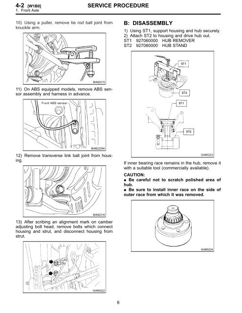
- Page 45: 1. Front Axle A: REMOVAL 1) Disconn
- Page 49 and 50: 11) Attach hub to ST1 securely. 12)
- Page 51 and 52: 8) Disconnect parking brake cable e
- Page 53 and 54: 12) Remove bolts which secure later
- Page 55 and 56: 3) Clean housing interior completel
- Page 57 and 58: 10) Bleed air from brake system. 1
- Page 59 and 60: 2. REAR DRIVE SHAFT 1) Disconnect g
- Page 61 and 62: 8) Place alignment mark on trunnion
- Page 63 and 64: 3) Apply a coat of specified grease
- Page 65 and 66: 3) Insert DOJ cage onto shaft. NOTE
- Page 67 and 68: CAUTION: Use a new axle nut. Alwa
- Page 69 and 70: 5. Steel Wheel and Tire A: INSPECTI
- Page 71 and 72: 8. Tire Rotation If tires are maint
- Page 73 and 74: 4-3 [S1A0] SPECIFICATIONS AND SERVI
- Page 75 and 76: 4-3 [S1C0] SPECIFICATIONS AND SERVI
- Page 77 and 78: 4-3 [C200] COMPONENT PARTS 2. Power
- Page 79 and 80: 4-3 [C300] COMPONENT PARTS 3. Power
- Page 81 and 82: 4-3 [W2B0] SERVICE PROCEDURE 2. Til
- Page 83 and 84: 4-3 [W2D0] SERVICE PROCEDURE 2. Til
- Page 85 and 86: 4-3 [W3A0] SERVICE PROCEDURE 3. Ste
- Page 87 and 88: 4-3 [W3C0] SERVICE PROCEDURE 3. Ste
- Page 89 and 90: 4-3 [W3C3] SERVICE PROCEDURE 3. Ste
- Page 91 and 92: 4-3 [W3D0] SERVICE PROCEDURE 3. Ste
- Page 93 and 94: 4-3 [W3F0] SERVICE PROCEDURE 3. Ste
- Page 95 and 96: 4-3 [W4B0] SERVICE PROCEDURE 4. Con
- Page 97 and 98:
4-3 [W4C2] SERVICE PROCEDURE 4. Con
- Page 99 and 100:
4-3 [W4D1] SERVICE PROCEDURE 4. Con
- Page 101 and 102:
4-3 [W5A0] SERVICE PROCEDURE 5. Pip
- Page 103 and 104:
4-3 [W5C0] SERVICE PROCEDURE 5. Pip
- Page 105 and 106:
4-3 [W6A0] SERVICE PROCEDURE 6. Oil
- Page 107 and 108:
4-3 [W6B1] SERVICE PROCEDURE 6. Oil
- Page 109 and 110:
4-3 [W6D0] SERVICE PROCEDURE 6. Oil
- Page 111 and 112:
4-3 [W6E0] SERVICE PROCEDURE 6. Oil
- Page 113 and 114:
4-3 [W7A0] SERVICE PROCEDURE 7. Pow
- Page 115 and 116:
4-3 [K1B0] DIAGNOSTICS 1. Power Ste
- Page 117 and 118:
4-3 [K1C0] DIAGNOSTICS 1. Power Ste
- Page 119 and 120:
4-3 [K1C0] DIAGNOSTICS 1. Power Ste
- Page 121 and 122:
4-3 [K1E0] DIAGNOSTICS 1. Power Ste
- Page 123 and 124:
4-3 [K1F0] DIAGNOSTICS 1. Power Ste
- Page 125 and 126:
4-3 DIAGNOSTICS MEMO: 54
- Page 127 and 128:
2. 2500 cc MODEL SPECIFICATIONS AND
- Page 129 and 130:
1. Front Disc Brake A: EXCEPT 2500
- Page 131 and 132:
2. Rear Disc Brake (1) Caliper body
- Page 133 and 134:
4. Master Cylinder A: WITH ABS VEHI
- Page 135 and 136:
5. Brake Booster A: MODELS WITH ABS
- Page 137 and 138:
B: ABS CONTROL MODULE AND HYDRAULIC
- Page 139 and 140:
1. Front Disc Brake A: ON-CAR SERVI
- Page 141 and 142:
5) Remove disc rotor from hub. NOTE
- Page 143 and 144:
1) Clean mud and foreign particles
- Page 145 and 146:
1) Clean mud and foreign particles
- Page 147 and 148:
F: INSTALLATION 1) Install disc rot
- Page 149 and 150:
B: REMOVAL (1) Caliper body (2) Air
- Page 151 and 152:
E: ASSEMBLY 1) Clean caliper body i
- Page 153 and 154:
NOTE: If it is difficult to remove
- Page 155 and 156:
D: ASSEMBLY 1. WHEEL CYLINDER 1) Cl
- Page 157 and 158:
4. Parking Brake (Rear Disc Brake)
- Page 159 and 160:
D: ADJUSTMENT 1. SHOE CLEARANCE 1)
- Page 161 and 162:
6. Brake Booster A: REMOVAL 1) Remo
- Page 163 and 164:
3. OPERATION CHECK 1) With engine o
- Page 165 and 166:
7) While holding hexagonal part of
- Page 167 and 168:
11) Remove bolt and clamp from rear
- Page 169 and 170:
11. Brake Fluid A: REPLACEMENT CAUT
- Page 171 and 172:
CAUTION: Do not disassemble or adju
- Page 173 and 174:
3. OUTPUT VOLTAGE Output voltage ca
- Page 175 and 176:
14. ABS Control Module and Hydrauli
- Page 177 and 178:
9) Remove air bleeder screws from t
- Page 179 and 180:
SERVICE PROCEDURE 4. CONDITIONS FOR
- Page 181 and 182:
15B2 : CHECK G SENSOR. Measure volt
- Page 183 and 184:
1. Entire Brake System DIAGNOSTICS
- Page 185 and 186:
4-5 [S100] SPECIFICATIONS AND SERVI
- Page 187 and 188:
4-5 [C1A2] COMPONENT PARTS 1. Pedal
- Page 189 and 190:
4-5 [W1A1] SERVICE PROCEDURE 1. Ped
- Page 191 and 192:
4-5 [W1A4] SERVICE PROCEDURE 1. Ped
- Page 193 and 194:
4-5 [W1C1] SERVICE PROCEDURE 1. Ped
- Page 195 and 196:
4-5 [W1F1] SERVICE PROCEDURE 1. Ped
- Page 197 and 198:
4-5 [W3A0] SERVICE PROCEDURE 3. Acc
- Page 199 and 200:
4-5 [K100] DIAGNOSTICS 1. Pedal Sys
- Page 201 and 202:
1. Heater Unit (1) Vent door (2) DE
- Page 203 and 204:
3. Control Unit (1) Temperature con
- Page 205 and 206:
3. Blower Motor Assembly A: REMOVAL
- Page 207 and 208:
4-7 [S100] SPECIFICATIONS 1. Specif
- Page 209 and 210:
4-7 [C200] COMPONENT PARTS 2. Intak
- Page 211 and 212:
4-7 [W1A0] SERVICE PROCEDURE 1. Saf
- Page 213 and 214:
4-7 [W300] SERVICE PROCEDURE 3. Too
- Page 215 and 216:
4-7 [W300] SERVICE PROCEDURE 3. Too
- Page 217 and 218:
4-7 [W4D0] SERVICE PROCEDURE 4. O-r
- Page 219 and 220:
4-7 [W600] SERVICE PROCEDURE 6. Dis
- Page 221 and 222:
4-7 [W7C0] SERVICE PROCEDURE 7. Eva
- Page 223 and 224:
4-7 [W8A0] SERVICE PROCEDURE 8. Lea
- Page 225 and 226:
4-7 [W8A7] SERVICE PROCEDURE 9. Lub
- Page 227 and 228:
4-7 [W11B0] SERVICE PROCEDURE 11. C
- Page 229 and 230:
4-7 [W11C0] SERVICE PROCEDURE 11. C
- Page 231 and 232:
4-7 [W13A0] SERVICE PROCEDURE 13. R
- Page 233 and 234:
4-7 [W15A0] SERVICE PROCEDURE 15. C
- Page 235 and 236:
4-7 [W17B0] SERVICE PROCEDURE 18. P
- Page 237 and 238:
4-7 [K200] DIAGNOSTICS 2. Performan
- Page 239 and 240:
4-7 [K200] DIAGNOSTICS 2. Performan
- Page 241 and 242:
4-7 [K400] DIAGNOSTICS 4. Compresso
- Page 243 and 244:
4-7 [K600] DIAGNOSTICS 6. Radiator
- Page 245 and 246:
4-7 [K800] DIAGNOSTICS 8. Condenser
- Page 247 and 248:
B: ELECTRICAL INSPECTION DIAGNOSTIC
- Page 249 and 250:
B4M1226B H4M1304A S4M0055A B4M2201C
- Page 251 and 252:
MEMO: DIAGNOSTICS 7 [T400] 4-4 4. S
- Page 253 and 254:
ABS sensor*2 (Wheel speed sensor) C
- Page 255 and 256:
6. Diagnostics Chart for On-board D
- Page 257 and 258:
Behavior of vehicle a) Directional
- Page 259 and 260:
1. CALLING UP A TROUBLE CODE 1) Tak
- Page 261 and 262:
MEMO: [T6D2] 4-4 DIAGNOSTICS 6. Dia
- Page 263 and 264:
7A1 : CHECK IF OTHER WARNING LIGHTS
- Page 265 and 266:
7A10 : CHECK POOR CONTACT IN CON- N
- Page 267 and 268:
7B1 : CHECK INSTALLATION OF ABSCM&H
- Page 269 and 270:
7B10 : CHECK WIRING HARNESS. Measur
- Page 271 and 272:
7C1 : CHECK DIAGNOSIS TERMINAL. Mea
- Page 273 and 274:
8. Diagnostics Chart with Trouble C
- Page 275 and 276:
8E1 : CHECK FRONT ABS SENSOR. 1) Tu
- Page 277 and 278:
DIAGNOSTICS 8E8 : CHECK BATTERY SHO
- Page 279 and 280:
DIAGNOSTICS 8E16 : CHECK GROUND SHO
- Page 281 and 282:
8I1 : CHECK INSTALLATION OF ABS SEN
- Page 283 and 284:
8I10 : CHECK RESISTANCE OF FRONT AB
- Page 285 and 286:
8I16 : CHECK GROUND SHORT OF HAR- N
- Page 287 and 288:
MEMO: DIAGNOSTICS [T8I23] 4-4 8. Di
- Page 289 and 290:
8J1 : CHECK IF THE WHEELS HAVE TURN
- Page 291 and 292:
MEMO: DIAGNOSTICS [T8J14] 4-4 8. Di
- Page 293 and 294:
8N1 : CHECK INPUT VOLTAGE OF ABSCM&
- Page 295 and 296:
8R1 : CHECK INPUT VOLTAGE OF ABSCM&
- Page 297 and 298:
8S1 : CHECK GROUND CIRCUIT OF ABSCM
- Page 299 and 300:
8T1 : CHECK GENERATOR. 1) Start eng
- Page 301 and 302:
MEMO: DIAGNOSTICS [T8T7] 4-4 8. Dia
- Page 303 and 304:
8U1 : CHECK SPECIFICATIONS OF THE A
- Page 305 and 306:
8U10 : CHECK ANY OTHER TROUBLE CODE
- Page 307 and 308:
8V1 : CHECK INPUT VOLTAGE OF ABSCM&
- Page 309 and 310:
MEMO: DIAGNOSTICS [T8V6] 4-4 8. Dia
- Page 311 and 312:
8W1 : CHECK INPUT VOLTAGE OF ABSCM&
- Page 313 and 314:
MEMO: DIAGNOSTICS [T8W8] 4-4 8. Dia
- Page 315 and 316:
8X1 : CHECK STOP LIGHTS COME ON. De
- Page 317 and 318:
8Y1 : CHECK ALL FOUR WHEELS FOR FRE
- Page 319 and 320:
DIAGNOSTICS 8Y8 : CHECK GROUND SHOR
- Page 321 and 322:
MEMO: DIAGNOSTICS [T8Y14] 4-4 8. Di
- Page 323 and 324:
6. FREEZE FRAME DATA NOTE: Data st
- Page 325 and 326:
B: LIST OF DIAGNOSTIC TROUBLE CODE
- Page 327 and 328:
10C1 : CHECK IGNITION SWITCH. : Is
- Page 329 and 330:
MEMO: DIAGNOSTICS 85 [T10C9] 4-4 10
- Page 331 and 332:
10D1 : CHECK WIRING HARNESS. 1) Tur
- Page 333 and 334:
MEMO: DIAGNOSTICS 89 [T10D6] 4-4 10
- Page 335 and 336:
WIRING DIAGRAM: DIAGNOSTICS 91 [T10
- Page 337 and 338:
10H7 : CHECK POOR CONTACT IN CON- N
- Page 339 and 340:
DIAGNOSTICS 10H16 : CHECK HARNESS/C
- Page 341 and 342:
10H23 : CHECK HUB RUNOUT. Measure h
- Page 343 and 344:
MEMO: DIAGNOSTICS 99 [T10H28] 4-4 1
- Page 345 and 346:
10L1 : CHECK OUTPUT OF ABS SENSOR U
- Page 347 and 348:
10L13 : CHECK ABS SENSOR SIGNAL. DI
- Page 349 and 350:
DIAGNOSTICS 10L21 : CHECK HARNESS/C
- Page 351 and 352:
10L28 : CHECK SHIELD CIRCUIT. DIAGN
- Page 353 and 354:
10M1 : CHECK IF THE WHEELS HAVE TUR
- Page 355 and 356:
MEMO: DIAGNOSTICS 111 [T10M14] 4-4
- Page 357 and 358:
10Q1 : CHECK INPUT VOLTAGE OF ABSCM
- Page 359 and 360:
10U1 : CHECK INPUT VOLTAGE OF ABSCM
- Page 361 and 362:
10V1 : CHECK GROUND CIRCUIT OF ABSC
- Page 363 and 364:
10W1 : CHECK GENERATOR. 1) Start en
- Page 365 and 366:
MEMO: DIAGNOSTICS 121 [T10W7] 4-4 1
- Page 367 and 368:
10X1 : CHECK GENERATOR. 1) Start en
- Page 369 and 370:
MEMO: DIAGNOSTICS 125 [T10X7] 4-4 1
- Page 371 and 372:
10Y1 : CHECK SPECIFICATIONS OF THE
- Page 373 and 374:
MEMO: DIAGNOSTICS 129 [T10Y8] 4-4 1
- Page 375 and 376:
DIAGNOSTICS 10Z1 : CHECK BATTERY SH
- Page 377 and 378:
MEMO: DIAGNOSTICS 133 [T10Z6] 4-4 1
- Page 379 and 380:
10AA1 : CHECK INPUT VOLTAGE OF ABSC
- Page 381 and 382:
10AB1 : CHECK VALVE RELAY IN ABSCM&
- Page 383 and 384:
10AC1 : CHECK INPUT VOLTAGE OF ABSC
- Page 385 and 386:
10AD1 : CHECK MOTOR RELAY IN ABSCM&
- Page 387 and 388:
10AE1 : CHECK INPUT VOLTAGE OF ABSC
- Page 389 and 390:
MEMO: DIAGNOSTICS 145 [T10AE8] 4-4
- Page 391 and 392:
10AF1 : CHECK OUTPUT OF STOP LIGHT
- Page 393 and 394:
MEMO: DIAGNOSTICS 149 [T10AF7] 4-4
- Page 395 and 396:
10AG1 : CHECK OUTPUT OF G SENSOR US
- Page 397 and 398:
10AG9 : CHECK G SENSOR. Measure vol
- Page 399 and 400:
10AH1 : CHECK OUTPUT OF G SENSOR US
- Page 401 and 402:
10AH15 : CHECK OPEN CIRCUIT IN G SE
- Page 403 and 404:
10AH21 : CHECK POOR CONTACT IN CONN
- Page 405 and 406:
10AI1 : CHECK OUTPUT OF G SENSOR US
- Page 407 and 408:
10AI10 : CHECK ABSCM&H/U. 1) Turn i
- Page 409 and 410:
10AJ1 : CHECK ALL FOUR WHEELS FOR F
- Page 411 and 412:
10AJ10 : CHECK G SENSOR. Measure vo
- Page 413 and 414:
B: CHECKING THE HYDRAULIC UNIT OPER


