Mechanical Components.pdf - Ken Gilbert
Mechanical Components.pdf - Ken Gilbert
Mechanical Components.pdf - Ken Gilbert

You also want an ePaper? Increase the reach of your titles
YUMPU automatically turns print PDFs into web optimized ePapers that Google loves.
4-4 [W14D0] SERVICE PROCEDURE<br />
14. ABS Control Module and Hydraulic Control Unit (ABSCM&H/U)<br />
D: ABS SEQUENCE CONTROL<br />
1) Under the ABS sequence control, after the<br />
hydraulic unit solenoid valve is driven, the operation<br />
of the hydraulic unit can be checked by means<br />
of the brake tester or pressure gauge.<br />
2) ABS sequence control can be started by diagnosis<br />
connector or select monitor.<br />
1. OPERATIONAL GUIDELINES OF THE<br />
ABS SEQUENCE CONTROL WITH<br />
DIAGNOSIS CONNECTOR<br />
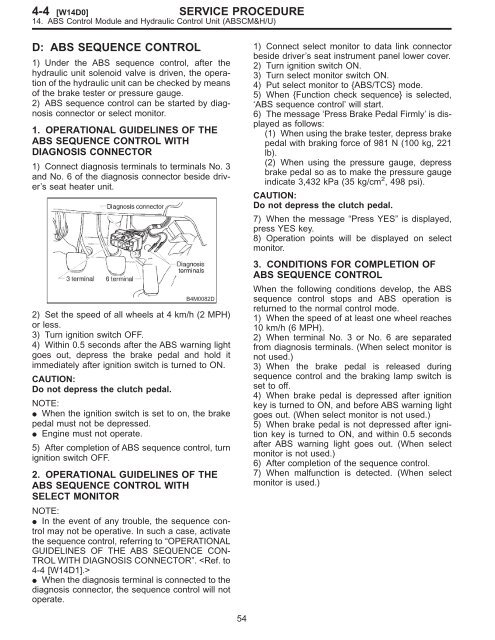
1) Connect diagnosis terminals to terminals No. 3<br />
and No. 6 of the diagnosis connector beside driver’s<br />
seat heater unit.<br />
B4M0082D<br />
2) Set the speed of all wheels at 4 km/h (2 MPH)<br />
or less.<br />
3) Turn ignition switch OFF.<br />
4) Within 0.5 seconds after the ABS warning light<br />
goes out, depress the brake pedal and hold it<br />
immediately after ignition switch is turned to ON.<br />
CAUTION:<br />
Do not depress the clutch pedal.<br />
NOTE:<br />
When the ignition switch is set to on, the brake<br />
pedal must not be depressed.<br />
Engine must not operate.<br />
5) After completion of ABS sequence control, turn<br />
ignition switch OFF.<br />
2. OPERATIONAL GUIDELINES OF THE<br />
ABS SEQUENCE CONTROL WITH<br />
SELECT MONITOR<br />
NOTE:<br />
In the event of any trouble, the sequence control<br />
may not be operative. In such a case, activate<br />
the sequence control, referring to “OPERATIONAL<br />
GUIDELINES OF THE ABS SEQUENCE CON-<br />
TROL WITH DIAGNOSIS CONNECTOR”. <br />
When the diagnosis terminal is connected to the<br />
diagnosis connector, the sequence control will not<br />
operate.<br />
54<br />
1) Connect select monitor to data link connector<br />
beside driver’s seat instrument panel lower cover.<br />
2) Turn ignition switch ON.<br />
3) Turn select monitor switch ON.<br />
4) Put select monitor to {ABS/TCS} mode.<br />
5) When {Function check sequence} is selected,<br />
‘ABS sequence control’ will start.<br />
6) The message ‘Press Brake Pedal Firmly’ is displayed<br />
as follows:<br />
(1) When using the brake tester, depress brake<br />
pedal with braking force of 981 N (100 kg, 221<br />
lb).<br />
(2) When using the pressure gauge, depress<br />
brake pedal so as to make the pressure gauge<br />
indicate 3,432 kPa (35 kg/cm 2 , 498 psi).<br />
CAUTION:<br />
Do not depress the clutch pedal.<br />
7) When the message “Press YES” is displayed,<br />
press YES key.<br />
8) Operation points will be displayed on select<br />
monitor.<br />
3. CONDITIONS FOR COMPLETION OF<br />
ABS SEQUENCE CONTROL<br />
When the following conditions develop, the ABS<br />
sequence control stops and ABS operation is<br />
returned to the normal control mode.<br />
1) When the speed of at least one wheel reaches<br />
10 km/h (6 MPH).<br />
2) When terminal No. 3 or No. 6 are separated<br />
from diagnosis terminals. (When select monitor is<br />
not used.)<br />
3) When the brake pedal is released during<br />
sequence control and the braking lamp switch is<br />
set to off.<br />
4) When brake pedal is depressed after ignition<br />
key is turned to ON, and before ABS warning light<br />
goes out. (When select monitor is not used.)<br />
5) When brake pedal is not depressed after ignition<br />
key is turned to ON, and within 0.5 seconds<br />
after ABS warning light goes out. (When select<br />
monitor is not used.)<br />
6) After completion of the sequence control.<br />
7) When malfunction is detected. (When select<br />
monitor is used.)