LOGIQ™ 400 - KKMed
LOGIQ™ 400 - KKMed
LOGIQ™ 400 - KKMed

You also want an ePaper? Increase the reach of your titles
YUMPU automatically turns print PDFs into web optimized ePapers that Google loves.
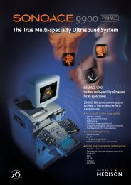
LOGIQ <strong>400</strong><br />
Quick Start Guide 2237879–100<br />
A Training in Partnership Program<br />
TiPTM<br />
GE Medical Systems<br />
Training In Partnership
LOGIQ <strong>400</strong><br />
Quick Start Guide 2237879–100<br />
A Training in Partnership Program<br />
TiPTM<br />
GE Medical Systems<br />
Training In Partnership
Regulatory Requirement<br />
This product complies with regulatory requirements of the following European Directive 93/42/EEC concerning medical<br />
devices<br />
This Quick Start Guide is a reference for LOGIQ <strong>400</strong> MD MR3 and LOGIQ <strong>400</strong>CL. It applies to all versions of 4.01<br />
software for the LOGIQ <strong>400</strong>. It applies to all versions of 4.02 software for the LOGIQ <strong>400</strong>CL.<br />
GE Medical Systems<br />
GE Medical Systems: Telex 3797371<br />
P.O. Box 414, Milwaukee, Wisconsin 53201 U.S.A.<br />
(Asia, Pacific, Latin America, North America)
REV DATE REASON FOR CHANGE<br />
0 April 27, 1999 Initial Release<br />
LOGIQ <strong>400</strong> Quick Start Guide<br />
2237879–100 Rev. 0<br />
<br />
<br />
<br />
TiP Cover Page N/A<br />
Title Page 0<br />
Revision History A and B 0<br />
Quick Start 1 thru Quick Start 40 0<br />
Revision History A
Revision History B<br />
Please verify that you are using the latest revision of this document. Information<br />
pertaining to this document is maintained on GPC (GE Medical Systems Global<br />
Product Configuration). If you need to know the latest revision, contact your<br />
distributor, local GE Sales Representative or in the USA call the GE Ultrasound<br />
Clinical Answer Center at 1-800-682-5327 or 414-524-5698.<br />
LOGIQ <strong>400</strong> Quick Start Guide<br />
2237879–100 Rev. 0
Introduction<br />
The Quick Start Guide (TRANSLATED) provides a step-by-step description of the basic features and<br />
operation of the LOGIQ <strong>400</strong>. It is intended to be used in conjunction with the Basic User Manual in order to<br />
provide the information necessary to operate the system safely.<br />
The Quick Start Guide takes the user from system familiarization through power on, patient data entry, exam<br />
category/preset selection, scan modes/adjustments, basic measurements, report pages, recording images<br />
and power off.<br />
The LOGIQ <strong>400</strong> manuals are written for users who are familiar with basic ultrasound principals and techniques. They do<br />
not include sonography training or clinical procedures.<br />
Prescription Device (for USA only)<br />
CAUTION: United States law restricts this device to sale or use by or on the order of a physician.<br />
LOGIQ <strong>400</strong> Quick Start Guide<br />
2237879–100 Rev. 0<br />
Quick Start 1
Front View<br />
The following are major features of the LOGIQ <strong>400</strong> system console. Most features come with the standard configuration,<br />
while other features are options to the standard console.<br />
1. VCR Microphone<br />
LOGIQ <strong>400</strong><br />
2. Probe Holder<br />
3. MOD Drive<br />
13<br />
1<br />
4. Physio Panel *<br />
12<br />
5. Probe Connectors (Port #2 and #3)<br />
6. Power Supply Filter<br />
11<br />
2<br />
7. Air Filter<br />
10<br />
3<br />
8. Probe Parking Port (Port #1)<br />
9. On/Off Switch<br />
10. B/W Page Printer *<br />
9<br />
4<br />
11. Keyboard<br />
12. Keyboard Task Light<br />
13. Task Light Switch<br />
8<br />
5<br />
* = optional feature or accessory<br />
Quick Start 2<br />
7 6<br />
Î<br />
LOGIQ <strong>400</strong> Quick Start Guide<br />
2237879–100 Rev. 0
Back View<br />
7<br />
6<br />
5<br />
4<br />
3<br />
LOGIQ <strong>400</strong> Quick Start Guide<br />
2237879–100 Rev. 0<br />
ÎÎ ÎÎÎ<br />
ÎÎÎ ÎÎÎ ÎÎ<br />
ÎÎÎ ÎÎ<br />
1 ON<br />
0 OFF<br />
ON<br />
2<br />
1<br />
1. Circuit Breaker<br />
2. Air Filter<br />
3. Cable Access<br />
4. Peripheral Cable Access Door<br />
5. Handle for Pushing<br />
6. Monitor Arm Swivel Lock<br />
7. Color Monitor<br />
Optional Freeze/Record Foot Switch<br />
Freeze<br />
Record<br />
Quick Start 3
Power On<br />
On<br />
Quick Start 4<br />
To connect the system to the electrical supply:<br />
Ensure that the wall outlet is a minimum 15 amp dedicated circuit for 120 VAC (USA) or 7.5<br />
amp dedicated circuit for 220–240 VAC (Europe).<br />
Make sure that the power switch is turned off.<br />
Unwrap the power cable. Make sure to allow sufficient slack in the cable so that the plug is<br />
not pulled out of the wall if the system is moved slightly.<br />
Push the power plug securely into the wall outlet.<br />
To power on the system, ensure that the Circuit Breaker, located on the back of the power<br />
supply near the bottom of the unit, is turned on.<br />
Press the Power On Power Off/Stand-by switch, located to the left of the probe connectors, to<br />
the on position.<br />
LOGIQ <strong>400</strong> Quick Start Guide<br />
2237879–100 Rev. 0
Power On (cont’d)<br />
During power up, the screen display changes as the system runs its self diagnostics.<br />
Start of<br />
diagnostic<br />
XXXXXXX<br />
LOGIQ <strong>400</strong> Quick Start Guide<br />
2237879–100 Rev. 0<br />
XXXXXXX<br />
Version X.XX Version X.XX<br />
End of<br />
diagnostic<br />
Version X.XX<br />
Quick Start 5
Control Panel Layout<br />
Keyboard<br />
Keyboard controls have been arranged<br />
according to function and usage. This helps<br />
minimize operator movement while scanning.<br />
1. Alphanumeric Keys<br />
2. New Patient<br />
3. Probe Select<br />
4. Soft Menu Controls<br />
9<br />
5. User Define<br />
6. Mode, Display and Record<br />
7. Measurement and Annotation<br />
8. TGC<br />
8<br />
9. Doppler and CFM<br />
Quick Start 6<br />
<br />
<br />
7<br />
1<br />
Ø<br />
Ç<br />
Æ<br />
6<br />
2<br />
LOGIQ <strong>400</strong> Quick Start Guide<br />
2237879–100 Rev. 0<br />
3<br />
4<br />
5
Soft Menu Control Panel<br />
The Soft Menu Display has 8 Top Menu selections (Mode,<br />
Preset, Set Up, ECG, Archive, DICOM, AutoSeq and Cine)<br />
and 8 Sub Menu selections (varies depending on choice of<br />
Top Menu selection) available.<br />
The Top Menu Select key toggles the soft menu display<br />
on/off or returns to the top menu display from a sub menu.<br />
The Sub Menu Select keys turn on a sub menu, move<br />
through the sub menu selections and pages, change sub<br />
menu values or turn on/off sub menu selections.<br />
The up/down arrow keys turn on the sub menu.<br />
The left/right arrow keys move through the menu selections<br />
and pages.<br />
+ <br />
} or Previous Page<br />
+ <br />
The up/down arrow keys change the highlighted<br />
selection value or turn the sub menu selection on/off.<br />
LOGIQ <strong>400</strong> Quick Start Guide<br />
2237879–100 Rev. 0<br />
+ <br />
or<br />
}<br />
+ Next Page<br />
or<br />
+<br />
1<br />
2<br />
LOGIQ <strong>400</strong> MD<br />
B 1/4<br />
Dynamic Gray Focus Focus<br />
Range Map Number Positn<br />
40 B–2 2<br />
1. Top Menu Selections<br />
2. Sub Menu Selections<br />
Quick Start 7
Probe Controls<br />
Probe Ports<br />
Quick Start 8<br />
A probe is activated by pressing the Probe Select key. The appropriate port’s LED (light<br />
emitting diode) to the left of the key is lit.<br />
The second key is used to select (activate) the dedicated continuous wave Doppler (CWD)<br />
probe.<br />
All imaging probes can be plugged into either the number<br />
two or number three probe port positions. Probe port<br />
position number one is inactive (probe parking port). It<br />
can be activated by purchasing the third probe port<br />
option.<br />
<br />
NOTE: Ensure that the probe port is<br />
deactivated and the image is frozen before<br />
disconnecting the probe.<br />
Probe Port Position 1<br />
(Standard Version Inactive—Parking Port)<br />
Single CWD Probe Connection<br />
lock<br />
unlock<br />
LOGIQ <strong>400</strong> Quick Start Guide<br />
2237879–100 Rev. 0
Starting an Exam<br />
Patient Entry Menu<br />
Press the New Patient key at the beginning<br />
of each study to reset the system and enter<br />
new patient data. When the New Patient key<br />
is pressed, the Patient Entry menu appears.<br />
Ensure that the Blue Shift key is not active.<br />
Use the Trackball to move the highlight cursor to the Exam<br />
Category Selection line. Enter the desired exam number and fill in<br />
the appropriate patient data.<br />
Highlight EXIT and press Return or press New Patient again when<br />
the patient entry menu data has been completed.<br />
The system takes a few seconds to load new exam category<br />
parameters and calibrate the attached transducers before entering<br />
the scan mode.<br />
LOGIQ <strong>400</strong> Quick Start Guide<br />
2237879–100 Rev. 0<br />
Quick Start 9
Application Presets<br />
Select the exam category application preset,<br />
that best describes the desired study to be<br />
performed, from the factory default preset<br />
selections displayed on the monitor.<br />
Quick Start 10<br />
Select the desired probe.<br />
Preset 1/2 LOGIQ <strong>400</strong> MD<br />
General Tech Fetal Newborn<br />
OB Diff Heart<br />
Preset 1/2<br />
General Tech Fetal Newborn<br />
OB Diff Heart<br />
LOGIQ <strong>400</strong> Quick Start Guide<br />
2237879–100 Rev. 0
Scan Mode Controls<br />
LOGIQ <strong>400</strong> Quick Start Guide<br />
2237879–100 Rev. 0<br />
Select the desired display mode or combination of display modes (B-Mode, Pulsed Doppler, Color<br />
Flow Mode, M-Mode or Continuous Wave Doppler Mode).<br />
To select CWD Mode, press Blue Shift and X. CWD Mode is available for sector probe only.<br />
If the dual display mode (split screen) is desired, the L and R keys activate the Left or Right<br />
displayed image.<br />
Scan the desired anatomy. Change modes as desired. Use the mode controls to adjust the image<br />
as necessary.<br />
Quick Start 11
B-Mode Controls<br />
There are four Soft-Menu pages for B-Mode imaging adjustments.<br />
B 1/4<br />
Dynamic Range—Controls how echo intensities are converted to shades of<br />
gray, thereby creating a range of gray scale that can be adjusted.<br />
Dynamic<br />
Range<br />
Gray<br />
Map<br />
Quick Start 12<br />
Focus<br />
Number<br />
42 B–2 2<br />
B 2/4<br />
Frame<br />
Average<br />
Imaging<br />
Freq<br />
OFF 3.5MHz<br />
B 3/4<br />
Focus<br />
Positn<br />
Color<br />
Tag<br />
Image<br />
Softner<br />
Tag<br />
Positn<br />
Color<br />
3D<br />
Mode<br />
Gray Map—Determines how the echo intensity levels received are presented<br />
as shades of gray.<br />
Focus Number—Changes the number of focal zones so that the beam can<br />
be tightened or expanded for a specific area.<br />
Frame Average—Averages previous frames of image data with the current<br />
frame.<br />
Imaging Freq—Allows more echoes to pass through.<br />
Image Softner—Adjust for the amount of smoothing applied.<br />
Color—Allows for enabling B-Mode image colorization.<br />
3D Mode—Allows for 3D Mode option activation.<br />
Color Tag—Enables the colorization of a specific gray scale level range.<br />
Tag Position—Allows for the movement of the specified color tag range<br />
throughout the gray scale displayed.<br />
Focus Positn—Changes the depth at which the selected number of focal<br />
zones are optimized.<br />
LOGIQ <strong>400</strong> Quick Start Guide<br />
2237879–100 Rev. 0
B-Mode Controls (cont’d)<br />
B 4/4<br />
Biopsy<br />
Zone<br />
Image<br />
Rotatn<br />
Rejectn Edge<br />
Enhance<br />
SGL 0 DEG 30 MID<br />
LOGIQ <strong>400</strong> Quick Start Guide<br />
2237879–100 Rev. 0<br />
Biopsy Zone—Enables the electronic guidezone(s) available for the active<br />
probe.<br />
Image Rotate—Rotates the single real-time or zoomed B-Mode image in 90°<br />
increments.<br />
Rejectn—Allows for the elimination of low level echoes from the display.<br />
B Edge Enhance—Brings out subtle tissue differences and boundaries by<br />
enhancing the gray scale differences corresponding to the edges of<br />
structures.<br />
Quick Start 13
B-Mode Controls (cont’d)<br />
The keyboard controls that effect B-Mode are as follows:<br />
Quick Start 14<br />
7<br />
<br />
8<br />
1 2 3 4 5 6<br />
1. TGC—Balances the image so brightness is consistent throughout the image. Move the slide pot to the right to<br />
increase or the left to decrease.<br />
2. Scan Area—Used to assign trackball control to adjust size/position B-Mode sector display, CFM window, and<br />
horizontal size/position of the real-time zoom window.<br />
3. Depth—To reduce depth (look at a shallower image), turn the Depth rotary encoder clockwise. To increase depth<br />
(look at a deeper image), turn the Depth rotary encoder counterclockwise.<br />
9<br />
LOGIQ <strong>400</strong> Quick Start Guide<br />
2237879–100 Rev. 0
B-Mode Controls (cont’d)<br />
4. Display Format (Dual)— Left/Right split screen display.<br />
5. Reverse—The GE logo at the top of the sector wedge corresponds to the orientation mark on the probe body. When<br />
Reverse is active, the image flips and the GE logo switches to correspond to the probe mark.<br />
6. B/M Gain—Controls the gain of the displayed echoes. To increase/decrease, turn the control clockwise/<br />
counterclockwise.<br />
7. Audio Volume—In B-, B/M- and M-Modes, Acoustic Output can be adjusted with this knob.<br />
8. Angle—Controls the gain in B/M and CFM-B/M Mode.<br />
9. Focus Position—While in B-Mode only, Baseline Shift can be used to change Focus Position.<br />
LOGIQ <strong>400</strong> Quick Start Guide<br />
2237879–100 Rev. 0<br />
Quick Start 15
B-Mode Controls (cont’d)<br />
Quick Start 16<br />
B-Mode Optimization<br />
Adjustments for... Do the Following... Adjustments for... Do the Following...<br />
Image too grainy 1. Increase Dynamic Range.<br />
2. Increase Frame Average.<br />
3. Decrease Edge Enhance.<br />
4. Change Gray Map.<br />
Image too noisy 1. Decrease B/M GAIN.<br />
2. Decrease Dynamic Range.<br />
3. Increase Frame Average.<br />
4. Increase Edge Enhance.<br />
Cystic Imaging 1. Decrease the B/M GAIN.<br />
2. Decrease Dynamic Range.<br />
3. Use SCAN AREA SIZE to reduce<br />
image width.<br />
4. Change Focus Number to increase<br />
number of focal zones.<br />
5. Optimize focal zone placement.<br />
Image too soft 1. Decrease Dynamic Range.<br />
2. Increase Edge Enhance.<br />
3. Decrease Frame Average.<br />
4. Change Gray Map.<br />
Improve Uniformity 1. Increase the number of focal zones.<br />
Technically Difficult<br />
Patients<br />
2. Decrease SCAN AREA SIZE.<br />
3. Adjust TGC to compensate for<br />
attenuation.<br />
1. Select the proper probe or change<br />
Imaging Freq. for the exam (larger<br />
patient, lower frequency).<br />
2. Increase ACOUSTIC OUTPUT, if<br />
necessary.<br />
3. Maintain a lower Dynamic Range<br />
(45 to 48).<br />
4. Decrease SCAN AREA SIZE for<br />
faster frame rates.<br />
LOGIQ <strong>400</strong> Quick Start Guide<br />
2237879–100 Rev. 0
Color Flow Mode (CFM) Controls<br />
There are four Soft-Menu pages for Color Flow Mode imaging adjustments.<br />
CFM 1/4<br />
CFM Map—Allows for the selection of how Doppler velocities are mapped as<br />
color over the gray scale.<br />
CFM<br />
Map<br />
Slant<br />
Scan<br />
VT–1 +<br />
CFM<br />
Frame<br />
Average<br />
MID<br />
2/4<br />
Penet<br />
Diag<br />
Mode<br />
MAP<br />
High<br />
Resoltn<br />
MTI<br />
Filter<br />
LOW<br />
Display<br />
Thrshld<br />
32<br />
LOGIQ <strong>400</strong> Quick Start Guide<br />
2237879–100 Rev. 0<br />
Capture<br />
OFF<br />
Slant Scan—Used to control the position of the CFM window for linear<br />
probes only.<br />
Diag Mode—Allows for the selection of the best color flow display format.<br />
MTI Filter—Filters out low flow velocity color.<br />
Frame Average—Averages color information from previous frames with the<br />
current frame.<br />
Penet—Penetration can be increased by lowering the operating frequency of<br />
the active probe.<br />
High Resoltn—Provides a quick way to maximize resolution for the CFM<br />
display.<br />
Display Thrshld—Gray scale level at which the overlay of color information<br />
stops.<br />
Capture—Displays the highest mean velocity (average velocity) detected<br />
over a specific time interval.<br />
Quick Start 17
Color Flow Mode (CFM) Controls (cont’d)<br />
CFM 3/4<br />
Packet<br />
Size<br />
Spatial<br />
Filter<br />
SMALL OFF<br />
CFM<br />
ACE<br />
4/4<br />
Noise<br />
Blanker<br />
Quick Start 18<br />
W.E.<br />
Cancel<br />
Persist<br />
ence<br />
OFF OFF OFF<br />
Color<br />
Tag<br />
Tag<br />
Positn<br />
Packet Size—Controls the number of samples gathered for a single color<br />
flow vector.<br />
Spatial Filter—Smooths color information so that it is less grainy. Averages<br />
the color information out over time.<br />
W. E. Cancel—Eliminates the low velocity echoes caused by the motion of<br />
vessel walls.<br />
Color Tag—Allows for the assignment of a single color to a range of<br />
velocities.<br />
Tag Positn—Allows for the movement of the specified color tag range<br />
throughout the gray scale displayed.<br />
ACE—Reduces “color artifact noise”.<br />
Noise Blanker—Reduces the random noise generated due to the increase in<br />
Color Gain.<br />
Persistence—Retains the largest pixel color value until a larger value is<br />
detected or preset time has elapsed.<br />
LOGIQ <strong>400</strong> Quick Start Guide<br />
2237879–100 Rev. 0
Color Flow Mode (CFM) Controls (cont’d)<br />
Acoustic output affects the transmit power for both B-Mode and CFM signals.<br />
TGC and B/M Gain function only on the B-Mode image displayed.<br />
The Dual Format keys work the same as in dual B-Mode, but both B-Mode and CFM are displayed on the left and right<br />
sides of the screen.<br />
The keyboard controls that effect CFM are as follows:<br />
1<br />
2 3 4<br />
1. Color Doppler Gain—Adjusted overall<br />
received echo gain for CFM. To<br />
increase/decrease, turn the control<br />
clockwise/counterclockwise.<br />
<br />
2. CFM/Spectrum Invert—Inverts Color<br />
Flow Map assignments.<br />
3. Velocity Scale—Adjusts velocity scale to<br />
accommodate faster/slower blood flow<br />
velocities. To increase/decrease, press<br />
the Velocity Scale up/down arrow key.<br />
4. Baseline Shift—Minimize aliasing by<br />
assigning more of the overall displayed<br />
velocity scale to forward or reverse flow.<br />
To shift the baseline up/down, press the Baseline Shift up/down arrow key.<br />
5<br />
5. Color Flow Window Size (Scan Area)—Used to assign trackball control to adjust size/position of the CFM window.<br />
LOGIQ <strong>400</strong> Quick Start Guide<br />
2237879–100 Rev. 0<br />
Quick Start 19
Color Flow Mode (CFM) Controls (cont’d)<br />
Quick Start 20<br />
2. Decrease VELOCITY SCALE.<br />
3. Increase ACOUSTIC OUTPUT.<br />
4. Switch Penet. on and High Resoltn<br />
on.<br />
5. Decrease W.E. Cancel.<br />
6. Increase Frame Average (this<br />
allows gain to increase).<br />
7. Increase Packet Size.<br />
8. Reduce SCAN AREA SIZE to<br />
smallest size reasonable.<br />
9. Optimize focal zone position.<br />
Color Flow Mode Optimization<br />
Adjustments for... Do the Following... Adjustments for... Do the Following...<br />
Decrease Motion<br />
Artifact<br />
1. Increase the VELOCITY SCALE.<br />
2. Increase W.E. Cancel.<br />
Eliminate Aliasing 1. Increase VELOCITY SCALE.<br />
2. Lower BASELINE SHIFT.<br />
Improve Sensitivity 1. Increase GAIN.<br />
Improve Frame 1. Decrease color window using<br />
Rate/Flow Dynamics SCAN AREA SIZE width.<br />
Decrease Color Flow<br />
Bleeding<br />
1. Decrease GAIN.<br />
2. increase VELOCITY SCALE.<br />
3. Decrease Display Thrshld.<br />
2. Exit COLOR FLOW to reduce<br />
B-Mode image width (use SCAN<br />
AREA SIZE).<br />
3. Decrease DEPTH.<br />
4. Increase VELOCITY SCALE (if<br />
flow state allows it).<br />
5. Decrease Frame Average.<br />
LOGIQ <strong>400</strong> Quick Start Guide<br />
2237879–100 Rev. 0
Doppler Controls<br />
There are three Soft-Menu pages for Pulsed Wave Doppler (PWD) imaging adjustments.<br />
PWD 1/4<br />
Dynamic<br />
Range<br />
Slant<br />
Scan<br />
40 +<br />
PWD 2/4<br />
Sweep<br />
Speed<br />
Penet<br />
MID OFF<br />
Wall<br />
Filter<br />
20.2<br />
Color<br />
OFF<br />
S.V.<br />
Length<br />
Color<br />
Tag<br />
LOGIQ <strong>400</strong> Quick Start Guide<br />
2237879–100 Rev. 0<br />
5<br />
Tag<br />
Positn<br />
Dynamic Range—Controls how echo intensities are converted to<br />
shades of gray, thereby creating a range of gray scale that can be<br />
adjusted.<br />
Slant Scan—Controls the position of the Doppler cursor for linear<br />
probes only.<br />
Wall Filter—Removes the low level, low frequency Doppler signal<br />
caused by movement of the vessel walls.<br />
S. V. Length—Changes the size of the sample volume gate length.<br />
Sweep Speed—Changes the speed at which the timeline updates<br />
across the display.<br />
Penet—Penetration can be increased by lowering the operating<br />
frequency of the active probe.<br />
Color—Allows for enabling PWD or CWD Mode image colorization.<br />
Color Tag—Enables the colorization of a specific gray scale level<br />
range.<br />
Tag Positn—Allows for the movement of the specified color tag<br />
range throughout the gray scale displayed.<br />
Quick Start 21
Doppler Controls (cont’d)<br />
PWD 3/4<br />
Rejectn CFM/PWD<br />
Ratio<br />
Quick Start 22<br />
Rejectn—Allows for the elimination of low level echoes from the<br />
display.<br />
CFM/PWD Ratio—Used to set the velocity ratio between PWD and<br />
CFM. Active in triplex mode.<br />
CFM Shrink—Reduces the CFM window to specified size.<br />
Realtim Trace—Automatically traces in real-time.<br />
Calc Dir.—Choose which part of the Doppler Trace is used for<br />
automatic measurements/calculations.<br />
Trace Method—Choose the method used to trace the Doppler<br />
waveform in real-time (Peak, Floor, Mean or Mode).<br />
There are 3 Soft-Menu pages for Continuous Wave Doppler (CWD) imaging adjustments.<br />
CWD 1/4<br />
Dynamic<br />
Range<br />
OFF 1/2<br />
PWD 4/4<br />
Realtim<br />
Trace<br />
Calc<br />
Dir.<br />
OFF Compo<br />
Slant<br />
Scan<br />
40 +<br />
CFM<br />
Shrink<br />
Trace<br />
Method<br />
PEAK<br />
Wall<br />
Filter<br />
20.2<br />
Auto<br />
Trace<br />
CWD<br />
Sweep<br />
Speed<br />
MID<br />
2/4<br />
Color<br />
OFF<br />
Color<br />
Tag<br />
OFF<br />
Tag<br />
Positn<br />
CWD<br />
Rejectn<br />
OFF<br />
3/4<br />
PWD 4/4<br />
Realtim<br />
Trace<br />
Calc<br />
Dir.<br />
OFF Compo<br />
Trace<br />
Method<br />
PEAK<br />
LOGIQ <strong>400</strong> Quick Start Guide<br />
2237879–100 Rev. 0
Doppler Controls (cont’d)<br />
Several controls affect the B-Mode portion of the display and not the echoes in the Doppler spectrum. These are TGC,<br />
Depth, B/M Gain, Scan Area and Reverse keys. See Quick Start 12 for comments on these controls.<br />
The keyboard controls that affect Doppler are as follows:<br />
2 3 4 5 6 7 8<br />
1. M/D Cursor—Assigns trackball control to the Doppler cursor.<br />
2. Audio Volume—Used to adjust Doppler audio volume output.<br />
To increase/decrease, turn the control clockwise/<br />
counterclockwise.<br />
<br />
3. Doppler Spectral Gain—Adjusts overall received echo gain for<br />
Doppler. To increase/decrease, turn the control clockwise/<br />
counterclockwise.<br />
4. Theta Angle Correction—Adjusts angle correction for flow<br />
velocity calculation. To adjust the angle clockwise/<br />
counterclockwise relative to the probe face, turn the control<br />
clockwise/counterclockwise.<br />
1<br />
5. CFM/Spectrum Invert—Inverts Doppler spectrum assignments.<br />
6. Velocity Scale—Adjusts velocity scale to accommodate faster/slower blood flow velocities. To increase/decrease,<br />
press the Velocity Scale up/down arrow key.<br />
7. Baseline Shift—Minimize aliasing by assigning more of the overall displayed velocity scale to forward or reverse flow.<br />
To shift the baseline up/down, press the Baseline Shift up/down arrow key.<br />
8. B Pause—Freezes the B-Mode image while keeping the Doppler spectrum display active. Press to view CW Doppler.<br />
LOGIQ <strong>400</strong> Quick Start Guide<br />
2237879–100 Rev. 0<br />
Quick Start 23
Doppler Controls (cont’d)<br />
Quick Start 24<br />
Doppler Mode Optimization<br />
Adjustments for... Do the Following... Adjustments for... Do the Following...<br />
Increase Sensitivity 1. Increase GAIN.<br />
Increase Spectral<br />
Clarity<br />
2. Increase ACOUSTIC OUTPUT.<br />
3. Decrease VELOCITY SCALE (if<br />
flow state allows it).<br />
4. Increase S.V. Length.<br />
5. Use lower frequency probe or use<br />
lower Doppler frequency on some<br />
applications.<br />
6. Activate B-PAUSE to freeze<br />
B-Mode image.<br />
Scan angle is critical to Doppler<br />
sensitivity.<br />
1. Activate B PAUSE to freeze<br />
B-Mode image.<br />
2. Increase ACOUSTIC OUTPUT.<br />
3. Decrease S.V. Length.<br />
4. Decrease GAIN.<br />
5. Decrease Dynamic Range.<br />
Improve Display<br />
Aesthetics<br />
1. Activate B PAUSE to freeze<br />
B-Mode image.<br />
2. Decrease GAIN.<br />
3. Increase ACOUSTIC OUTPUT.<br />
4. Use smaller sample volume size,<br />
whenever possible.<br />
5. Increase/decrease Dynamic<br />
Range.<br />
6. Adjust BASELINE SHIFT and<br />
VELOCITY SCALE to adjust<br />
spectral size.<br />
7. Lower Doppler Sweep Speed.<br />
LOGIQ <strong>400</strong> Quick Start Guide<br />
2237879–100 Rev. 0
M-Mode Controls<br />
There are two Soft-Menu pages for M-Mode imaging adjustments.<br />
M<br />
Dynamic<br />
Range<br />
M<br />
1/2<br />
Gray<br />
Map<br />
40 M–2<br />
2/2<br />
Sweep<br />
Speed<br />
Color Color Color<br />
Tag Tag<br />
MID OFF<br />
Rejectn Edge<br />
Enhance<br />
30 MID<br />
Tag<br />
Positn<br />
LOGIQ <strong>400</strong> Quick Start Guide<br />
2237879–100 Rev. 0<br />
Dynamic Range—Controls how echo intensities are converted to shades of gray,<br />
thereby creating a range of gray scale that can be adjusted.<br />
Gray Map—Determines how the echo intensity levels received are presented as<br />
shades of gray.<br />
Rejectn—Allows for the elimination of low level echoes from the display.<br />
Edge Enhance—Brings out subtle tissue differences and boundaries by enhancing<br />
the gray scale differences corresponding to the edges of structures.<br />
Sweep Speed—Changes the speed at which the timeline updates across the display.<br />
Color—Allows for enabling M-Mode image colorization.<br />
Color Tag—Enables the colorization of a specific gray scale level range.<br />
Tag Positn—Allows for the movement of the specified color tag range throughout the<br />
gray scale displayed.<br />
Quick Start 25
M-Mode Controls (cont’d)<br />
Since M-Mode is basically a single B-Mode scan vector displayed over time, basic controls that affect the B-Mode display<br />
also affect the M-Mode display. See Quick Start 12 for comments on these controls.<br />
TGC and Depth affect both the M-Mode and B-Mode displays.<br />
If the scan area size is reduced and the position changed, the M-Mode cursor will follow the position change to stay within<br />
the displayed scan area.<br />
The Dual Format keys work the same as in dual B-Mode, but both B-Mode and M-Mode are displayed on the left and right<br />
sides of the screen.<br />
The keyboard controls that effect M-Mode are as follows:<br />
1. B/M Gain—Controls the gain of the displayed timeline<br />
echoes. To increase/decrease, turn the control clockwise/<br />
counterclockwise.<br />
2. M/D Cursor—Assigns trackball control to the M-Mode<br />
cursor.<br />
3. Zoom—Enables real-time or freeze zoom function.<br />
3 2<br />
1<br />
Quick Start 26<br />
M-Mode Optimization<br />
Adjustments for... Do the Following... Adjustments for... Do the Following...<br />
Improve M-Mode 1. Increase/decrease B/M GAIN.<br />
2. Increase Dynamic Range.<br />
Increase Size of Area<br />
of Interest<br />
1. Use M-Mode ZOOM.<br />
LOGIQ <strong>400</strong> Quick Start Guide<br />
2237879–100 Rev. 0
Reviewing Cine Images<br />
LOGIQ <strong>400</strong> Quick Start Guide<br />
2237879–100 Rev. 0<br />
Press Freeze to stop image data acquisition.<br />
When Freeze is activated, rotate the Cine Scroll control to display individual image frames which<br />
were stored by the system.<br />
NOTE: Cine frame number 0 is the most current image. The higher the Cine frame number, the<br />
older the image.<br />
The depth, dynamic range, and gain parameters displayed on the screen are valid for Cine frame<br />
number zero only.<br />
Quick Start 27
Image Annotation<br />
Keyboard Annotation<br />
The annotation keyboard is always active. Upon power up or starting a new patient, the underscore cursor appears in the<br />
mode’s home position. Comments may be typed in at the non-blinking cursor.<br />
Pressing the Comment key assigns the trackball function to controlling the cursor.<br />
Quick Start 28<br />
The Trackball and Keyboard Arrow keys are used to move the cursor to the desired position on the<br />
image.<br />
When the blinking cursor is in the desired position, comments may be typed in. Annotations are<br />
entered in the type-over, not insert, mode. Be careful not to write over text when editing.<br />
LOGIQ <strong>400</strong> Quick Start Guide<br />
2237879–100 Rev. 0
Special Keys—Symbols<br />
<br />
LOGIQ <strong>400</strong> Quick Start Guide<br />
2237879–100 Rev. 0<br />
Blue Shift: Some special annotation symbols can be used by activating the Blue Shift key. Those<br />
keys have special symbols shown in blue on the keyboard.<br />
Activating Blue Shift causes the arrow, female and male symbols to be printed on the screen during<br />
the comment function when the keys shown are pressed.<br />
The Blue Shift key acts as a lock function (similar to Caps Lock key). Press again to exit the Blue<br />
Shift function.<br />
Special Keys—Language Symbols<br />
The Red Shift key enables the special symbols shown in red on the keyboard. The red<br />
symbols shown in the lower right portion of a key print when the Red Shift is active and that key<br />
is pressed.<br />
To print the red symbols shown in the upper right half of a key, type the desired letter that uses<br />
the symbol, activate Red Shift, hold down the normal Shift key and press the desired symbol<br />
key. Red symbols can be used in any language but can only be used with the proper<br />
designated letters.<br />
The Red Shift key acts as a lock function (similar to Caps Lock key). Press again to exit the Red<br />
Shift function.<br />
Quick Start 29
Body Patterns<br />
Quick Start 30<br />
Body patterns are a simple graphic of a portion of the anatomy that is frequently scanned. Press the<br />
Body Pattern key to activate Body Patterns.<br />
A body pattern, generally displayed in the lower left corner of the screen,<br />
appears.<br />
Cycle through the body patterns by pressing the Ellipse up or down arrow<br />
keys.<br />
A Probe Orientation Marker is used to illustrate the probe position. This<br />
marker can be placed with the Trackball and rotated with the Zoom<br />
Size/Rotation control.<br />
Press Set to complete the body pattern selection.<br />
Probe<br />
Orientation<br />
Marker<br />
LOGIQ <strong>400</strong> Quick Start Guide<br />
2237879–100 Rev. 0
Performing Basic Measurements<br />
Basic measurements are displayed on the monitor and not automatically entered into a report page unless a specific<br />
measurement/calculation is selected from the sub-menu. The specific measurement/calculation can be chosen before or<br />
after the basic measurement has been performed.<br />
Scan the desired anatomy and press Freeze.<br />
Key Pressed<br />
(while frozen)<br />
Once Distance<br />
Ellipse/Circle<br />
LOGIQ <strong>400</strong> Quick Start Guide<br />
2237879–100 Rev. 0<br />
B Spectral Doppler<br />
(with B)<br />
Twice Trace/Circle TAMAX/TAMIN/<br />
TAMEAN/TAMODE<br />
Three Times Gray Scale Echo Level 2 Velocities<br />
Slope/Time<br />
Interval<br />
MODE<br />
Peak Velocity Tissue Depth<br />
(Distance)<br />
M (with B) CFM (with B)<br />
Distance<br />
Ellipse/Circle<br />
Time Interval Trace/Circle<br />
Depth Difference<br />
Slope/Time Interval<br />
Point Velocity<br />
Four Times Arrow Mark * Time Interval Arrow Mark * Gray Scale Echo Level<br />
Five Times Arrow Mark * Arrow Mark *<br />
* Assuming the “Arrow Mark Display” preset is set to on.<br />
Quick Start 31
Distance (B-Mode) and Tissue Depth (M-Mode)<br />
Perform a distance measurement for calculations such as BPD, FL, CRL, LVIDd and LVPWs.<br />
→<br />
→<br />
Quick Start 32<br />
Press Measurement once.<br />
Use the Trackball to move the “” cursor to the measurement start point. Press Set to fix the<br />
measurement start point cursor and to display a second cursor.<br />
Use the Trackball to move the second “” cursor to the measurement end point. Press Set to<br />
complete the measurement and fix the Distance value displayed on the bottom part of the screen.<br />
LOGIQ <strong>400</strong> Quick Start Guide<br />
2237879–100 Rev. 0
Circumference/Area - Ellipse (B-Mode)<br />
Perform a circumference/area using the ellipse method for calculations such as AC, HC, LVAMd, LVAd and Volume.<br />
Press Measurement once.<br />
→<br />
→<br />
→<br />
LOGIQ <strong>400</strong> Quick Start Guide<br />
2237879–100 Rev. 0<br />
Use the Trackball to move the “” cursor to either end of the major axis of the area to measure.<br />
Press Set to fix the start point cursor.<br />
Use the Trackball to move the second cursor to the major axis measurement end point. Press the<br />
Ellipse up arrow key. An ellipse having an initial circle shape appears.<br />
Use the Trackball to position the ellipse, as necessary, and to size the measured axis. Press Set to<br />
complete the ellipse measurement and record the circumference and area.<br />
Quick Start 33
Circumference/Area - Ellipse (B-Mode) (continued)<br />
Prior to completing the ellipse measurement, the following keys can be used to fine tune the measurement.<br />
Press the Measurement key to toggle the activation of the measurement cursors.<br />
Quick Start 34<br />
Press the Ellipse up arrow key to increase the size of the minor axis.<br />
Press the Ellipse down arrow key to decrease the size of the minor axis.<br />
Press Clear once to erase the ellipse and the current data measured. The original cursor is<br />
displayed to restart the measurement. Pressing Clear a second time exits the measurement<br />
function without completing the measurement.<br />
Press Set to complete the ellipse measurement.<br />
LOGIQ <strong>400</strong> Quick Start Guide<br />
2237879–100 Rev. 0
Circumference/Area - Trace (B-Mode)<br />
Perform a circumference/area using the trace method for calculations such as AC, HC, LVAMd, LVAd and % Stenosis.<br />
Press Measurement twice to display a dot “” cursor on the screen.<br />
→<br />
→<br />
Peak Velocity (Doppler)<br />
LOGIQ <strong>400</strong> Quick Start Guide<br />
2237879–100 Rev. 0<br />
Use the Trackball to move the dot “” cursor to the measurement start point. Press Set to change<br />
the dot “” cursor to a “” cursor.<br />
Use the Trackball to trace the measurement area. Press Set to fix the Circumference value<br />
displayed on the bottom of the screen and calculate the area.<br />
NOTE: When using the trace method, the Zoom Size/Rotation knob can be used to edit the trace<br />
line. Turn it clockwise or counterclockwise to erase the line (bit by bit) back from its current point.<br />
The erase function is limited to a small portion of the most recent trace.<br />
Perform a peak velocity measurement for calculations such as RI, PI, S/D Ratio, Max PG and Mean PG.<br />
Press Measurement. The “” cursor with a vertical dotted line appears.<br />
→<br />
Use the Trackball to move the cursor to the desired point of measurement in the Doppler Spectrum.<br />
Press Set to fix the velocity cursor. The velocity measurement in m/s or cm/s will be displayed at<br />
the bottom of the screen.<br />
NOTE: The “Display MaxPG with Velocity” preset, located on Preset Program page 4, allows<br />
MaxPG to be displayed with the Peak Velocity measurement.<br />
Quick Start 35
Time Interval (M-Mode and Doppler)<br />
Perform a time interval measurement for calculations such as HR, PHT and ET.<br />
Press Measurement twice in M-Mode and four times in Doppler. A “” cursor with vertical dotted<br />
lines appears when the cursor is in the M-Mode timeline/Doppler spectrum.<br />
Use the Trackball to move the cursor to the measurement start point. Press Set to fix the first<br />
cursor.<br />
→<br />
Use the Trackball to move the second cursor to the measurement end point. Press Set to complete<br />
the measurement.<br />
→<br />
The time interval between the two cursors is displayed.<br />
Erasing Measurements<br />
Quick Start 36<br />
Pressing Clear or unfreezing the image erases all measurements and calculations on the display.<br />
Measurements and calculations, however, remain on the report pages.<br />
Pressing New Patient erases all measurements and calculations on the display and clears the<br />
report pages.<br />
Rotating the Cine Scroll control erases measurements.<br />
Adding a new measurement that exceeds the maximum number of allowable measurements erases<br />
the first or oldest measurement.<br />
LOGIQ <strong>400</strong> Quick Start Guide<br />
2237879–100 Rev. 0
Report Pages<br />
Specific diagnostic exam<br />
categories have report<br />
pages to summarize<br />
measurements and<br />
calculations performed<br />
while in that exam<br />
category. These<br />
categories are Obstetrics,<br />
Gynecology, Cardiology<br />
and Vascular.<br />
A report page can be<br />
displayed by pressing<br />
Measurement and<br />
selecting it from the<br />
measurement sub-menu.<br />
LOGIQ <strong>400</strong> Quick Start Guide<br />
2237879–100 Rev. 0<br />
Quick Start 37
Recording Images<br />
Image Memory<br />
→<br />
Printing<br />
Quick Start 38<br />
Press Image Memory to temporarily store the maximum of 8 images in system memory.<br />
The images are erased when the New Patient key is pressed or power is turned off.<br />
Press Image Recall to display the last image stored in system memory.<br />
Press Top Menu Select to display a sub-menu of all images stored in system memory. Use the<br />
Sub-Menu Select left/right arrow keys to highlight the desired image. Press the Sub-Menu Select<br />
down arrow key to display the image.<br />
After recall, comments, measurements and body patterns can be added to the image. The image is<br />
then available for printing or archival.<br />
Use the Record 1 or Record 2 keys to print the image/report page on a black/white or color (option)<br />
video page printer.<br />
The function of these keys was established during installation.<br />
LOGIQ <strong>400</strong> Quick Start Guide<br />
2237879–100 Rev. 0
VCR Functions<br />
<br />
<br />
Probe Cleaning/Disinfection<br />
LOGIQ <strong>400</strong> Quick Start Guide<br />
2237879–100 Rev. 0<br />
Press the Blue Shift key to activate the keyboard/VCR controls.<br />
Use with the Sony SVO–9500MD VCR. If a different model VCR is installed<br />
on the system, use the controls on the VCR.<br />
Probes should be cleaned and disinfected after each use. The Probe Immersion Levels are provided with the probe but<br />
are also pictured in the Probes chapter of the User Manual.<br />
<br />
NOTE: Special instructions for the E721 probe are found in the Probes chapter of the User Manual.<br />
Quick Start 39
Power Off<br />
On<br />
Quick Start 40<br />
To power down the system, press down on the Power On Power Off/Stand-by switch.<br />
After turning the power off, the system takes a few seconds to update certain parameters to the<br />
hard drive before the power is disconnected.<br />
NOTE: During this time the message<br />
“Do not pull Power Cable.”<br />
“Do not turn off Breaker.”<br />
flashes on the monitor. The message “WARNING: NOW START THE POWER OFF<br />
PROCESS.” is also displayed at the bottom of the screen.<br />
While the system is running during this power down process, do NOT turn off the<br />
circuit breaker in the back of the machine and do NOT unplug the system from the<br />
wall outlet.<br />
If the system has not turned off five minutes after pressing the power switch off,<br />
listen for hard drive activity. If there is no hard disk drive activity, the circuit<br />
breaker on the bottom of the power supply can be used to turn off the system. Do<br />
NOT turn off the circuit breaker while the hard disk is working.<br />
LOGIQ <strong>400</strong> Quick Start Guide<br />
2237879–100 Rev. 0