Practical UML - A Hands-On Introduction for Developers - Komputasi
Practical UML - A Hands-On Introduction for Developers - Komputasi
Practical UML - A Hands-On Introduction for Developers - Komputasi

You also want an ePaper? Increase the reach of your titles
YUMPU automatically turns print PDFs into web optimized ePapers that Google loves.
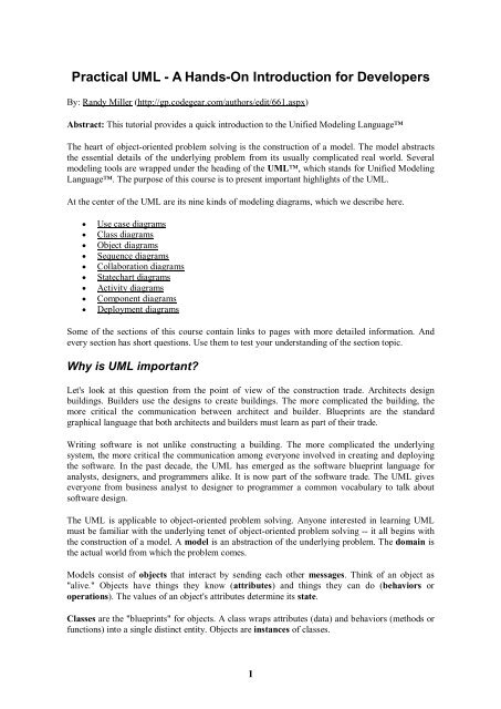
<strong>Practical</strong> <strong>UML</strong> - A <strong>Hands</strong>-<strong>On</strong> <strong>Introduction</strong> <strong>for</strong> <strong>Developers</strong><br />
By: Randy Miller (http://gp.codegear.com/authors/edit/661.aspx)<br />
Abstract: This tutorial provides a quick introduction to the Unified Modeling Language<br />
The heart of object-oriented problem solving is the construction of a model. The model abstracts<br />
the essential details of the underlying problem from its usually complicated real world. Several<br />
modeling tools are wrapped under the heading of the <strong>UML</strong>, which stands <strong>for</strong> Unified Modeling<br />
Language. The purpose of this course is to present important highlights of the <strong>UML</strong>.<br />
At the center of the <strong>UML</strong> are its nine kinds of modeling diagrams, which we describe here.<br />
Use case diagrams<br />
Class diagrams<br />
Object diagrams<br />
Sequence diagrams<br />
Collaboration diagrams<br />
Statechart diagrams<br />
Activity diagrams<br />
Component diagrams<br />
Deployment diagrams<br />
Some of the sections of this course contain links to pages with more detailed in<strong>for</strong>mation. And<br />
every section has short questions. Use them to test your understanding of the section topic.<br />
Why is <strong>UML</strong> important?<br />
Let's look at this question from the point of view of the construction trade. Architects design<br />
buildings. Builders use the designs to create buildings. The more complicated the building, the<br />
more critical the communication between architect and builder. Blueprints are the standard<br />
graphical language that both architects and builders must learn as part of their trade.<br />
Writing software is not unlike constructing a building. The more complicated the underlying<br />
system, the more critical the communication among everyone involved in creating and deploying<br />
the software. In the past decade, the <strong>UML</strong> has emerged as the software blueprint language <strong>for</strong><br />
analysts, designers, and programmers alike. It is now part of the software trade. The <strong>UML</strong> gives<br />
everyone from business analyst to designer to programmer a common vocabulary to talk about<br />
software design.<br />
The <strong>UML</strong> is applicable to object-oriented problem solving. Anyone interested in learning <strong>UML</strong><br />
must be familiar with the underlying tenet of object-oriented problem solving -- it all begins with<br />
the construction of a model. A model is an abstraction of the underlying problem. The domain is<br />
the actual world from which the problem comes.<br />
Models consist of objects that interact by sending each other messages. Think of an object as<br />
"alive." Objects have things they know (attributes) and things they can do (behaviors or<br />
operations). The values of an object's attributes determine its state.<br />
Classes are the "blueprints" <strong>for</strong> objects. A class wraps attributes (data) and behaviors (methods or<br />
functions) into a single distinct entity. Objects are instances of classes.<br />
1
Use case diagrams<br />
Use case diagrams describe what a system does from the standpoint of an external observer. The<br />
emphasis is on what a system does rather than how.<br />
Use case diagrams are closely connected to scenarios. A scenario is an example of what happens<br />
when someone interacts with the system. Here is a scenario <strong>for</strong> a medical clinic.<br />
"A patient calls the clinic to make an appointment <strong>for</strong> a yearly checkup. The receptionist<br />
finds the nearest empty time slot in the appointment book and schedules the appointment<br />
<strong>for</strong> that time slot. "<br />
A use case is a summary of scenarios <strong>for</strong> a single task or goal. An actor is who or what initiates<br />
the events involved in that task. Actors are simply roles that people or objects play. The picture<br />
below is a Make Appointment use case <strong>for</strong> the medical clinic. The actor is a Patient. The<br />
connection between actor and use case is a communication association (or communication <strong>for</strong><br />
short).<br />
Actors are stick figures. Use cases are ovals. Communications are lines that link actors to use<br />
cases.<br />
A use case diagram is a collection of actors, use cases, and their communications. We've put Make<br />
Appointment as part of a diagram with four actors and four use cases. Notice that a single use<br />
case can have multiple actors.<br />
Use case diagrams are helpful in three areas.<br />
determining features (requirements). New use cases often generate new requirements as<br />
the system is analyzed and the design takes shape.<br />
communicating with clients. Their notational simplicity makes use case diagrams a good<br />
way <strong>for</strong> developers to communicate with clients.<br />
generating test cases. The collection of scenarios <strong>for</strong> a use case may suggest a suite of<br />
test cases <strong>for</strong> those scenarios.<br />
2
Class diagrams<br />
A Class diagram gives an overview of a system by showing its classes and the relationships<br />
among them. Class diagrams are static -- they display what interacts but not what happens when<br />
they do interact.<br />
The class diagram below models a customer order from a retail catalog. The central class is the<br />
Order. Associated with it are the Customer making the purchase and the Payment. A Payment is<br />
one of three kinds: Cash, Check, or Credit. The order contains OrderDetails (line items), each<br />
with its associated Item.<br />
<strong>UML</strong> class notation is a rectangle divided into three parts: class name, attributes, and operations.<br />
Names of abstract classes, such as Payment, are in italics. Relationships between classes are the<br />
connecting links.<br />
Our class diagram has three kinds of relationships.<br />
association -- a relationship between instances of the two classes. There is an association<br />
between two classes if an instance of one class must know about the other in order to<br />
per<strong>for</strong>m its work. In a diagram, an association is a link connecting two classes.<br />
aggregation -- an association in which one class belongs to a collection. An aggregation<br />
has a diamond end pointing to the part containing the whole. In our diagram, Order has a<br />
collection of OrderDetails.<br />
generalization -- an inheritance link indicating one class is a superclass of the other. A<br />
generalization has a triangle pointing to the superclass. Payment is a superclass of Cash,<br />
Check, and Credit.<br />
An association has two ends. An end may have a role name to clarify the nature of the association.<br />
For example, an OrderDetail is a line item of each Order.<br />
A navigability arrow on an association shows which direction the association can be traversed or<br />
queried. An OrderDetail can be queried about its Item, but not the other way around. The arrow<br />
also lets you know who "owns" the association's implementation; in this case, OrderDetail has an<br />
Item. Associations with no navigability arrows are bi-directional.<br />
3
The multiplicity of an association end is the number of possible instances of the class associated<br />
with a single instance of the other end. Multiplicities are single numbers or ranges of numbers. In<br />
our example, there can be only one Customer <strong>for</strong> each Order, but a Customer can have any<br />
number of Orders.<br />
This table gives the most common multiplicities.<br />
Multiplicities Meaning<br />
0..1 zero or one instance. The notation n . . m<br />
indicates n to m instances.<br />
0..* or * no limit on the number of instances<br />
(including none).<br />
1 exactly one instance<br />
1..* at least one instance<br />
Every class diagram has classes, associations, and multiplicities. Navigability and roles are<br />
optional items placed in a diagram to provide clarity.<br />
Packages and object diagrams<br />
To simplify complex class diagrams, you can group classes into packages. A package is a<br />
collection of logically related <strong>UML</strong> elements. The diagram below is a business model in which the<br />
classes are grouped into packages.<br />
Packages appear as rectangles with small tabs at the top. The package name is on the tab or inside<br />
the rectangle. The dotted arrows are dependencies. <strong>On</strong>e package depends on another if changes in<br />
the other could possibly <strong>for</strong>ce changes in the first.<br />
Object diagrams show instances instead of classes. They are useful <strong>for</strong> explaining small pieces<br />
with complicated relationships, especially recursive relationships.<br />
This small class diagram shows that a university Department can contain lots of other<br />
Departments.<br />
4
The object diagram below instantiates the class diagram, replacing it by a concrete example.<br />
Each rectangle in the object diagram corresponds to a single instance. Instance names are<br />
underlined in <strong>UML</strong> diagrams. Class or instance names may be omitted from object diagrams as<br />
long as the diagram meaning is still clear.<br />
Sequence diagrams<br />
Class and object diagrams are static model views. Interaction diagrams are dynamic. They<br />
describe how objects collaborate.<br />
A sequence diagram is an interaction diagram that details how operations are carried out -- what<br />
messages are sent and when. Sequence diagrams are organized according to time. The time<br />
progresses as you go down the page. The objects involved in the operation are listed from left to<br />
right according to when they take part in the message sequence.<br />
Below is a sequence diagram <strong>for</strong> making a hotel reservation. The object initiating the sequence of<br />
messages is a Reservation window.<br />
5
The Reservation window sends a makeReservation() message to a HotelChain. The<br />
HotelChain then sends a makeReservation() message to a Hotel. If the Hotel has available<br />
rooms, then it makes a Reservation and a Confirmation.<br />
Each vertical dotted line is a lifeline, representing the time that an object exists. Each arrow is a<br />
message call. An arrow goes from the sender to the top of the activation bar of the message on<br />
the receiver's lifeline. The activation bar represents the duration of execution of the message.<br />
In our diagram, the Hotel issues a self call to determine if a room is available. If so, then the Hotel<br />
creates a Reservation and a Confirmation. The asterisk on the self call means iteration (to make<br />
sure there is available room <strong>for</strong> each day of the stay in the hotel). The expression in square<br />
brackets, [ ], is a condition.<br />
The diagram has a clarifying note, which is text inside a dog-eared rectangle. Notes can be put into<br />
any kind of <strong>UML</strong> diagram.<br />
Collaboration diagrams<br />
Collaboration diagrams are also interaction diagrams. They convey the same in<strong>for</strong>mation as<br />
sequence diagrams, but they focus on object roles instead of the times that messages are sent. In a<br />
sequence diagram, object roles are the vertices and messages are the connecting links.<br />
6
The object-role rectangles are labeled with either class or object names (or both). Class names are<br />
preceded by colons ( : ).<br />
Each message in a collaboration diagram has a sequence number. The top-level message is<br />
numbered 1. Messages at the same level (sent during the same call) have the same decimal prefix<br />
but suffixes of 1, 2, etc. according to when they occur.<br />
Statechart diagrams<br />
Objects have behaviors and state. The state of an object depends on its current activity or<br />
condition. A statechart diagram shows the possible states of the object and the transitions that<br />
cause a change in state.<br />
Our example diagram models the login part of an online banking system. Logging in consists of<br />
entering a valid social security number and personal id number, then submitting the in<strong>for</strong>mation<br />
<strong>for</strong> validation.<br />
Logging in can be factored into four non-overlapping states: Getting SSN, Getting PIN,<br />
Validating, and Rejecting. From each state comes a complete set of transitions that determine<br />
the subsequent state.<br />
7
States are rounded rectangles. Transitions are arrows from one state to another. Events or<br />
conditions that trigger transitions are written beside the arrows. Our diagram has two selftransition,<br />
one on Getting SSN and another on Getting PIN.<br />
The initial state (black circle) is a dummy to start the action. Final states are also dummy states<br />
that terminate the action.<br />
The action that occurs as a result of an event or condition is expressed in the <strong>for</strong>m /action.<br />
While in its Validating state, the object does not wait <strong>for</strong> an outside event to trigger a transition.<br />
Instead, it per<strong>for</strong>ms an activity. The result of that activity determines its subsequent state.<br />
Activity diagrams<br />
An activity diagram is essentially a fancy flowchart. Activity diagrams and statechart diagrams<br />
are related. While a statechart diagram focuses attention on an object undergoing a process (or on a<br />
process as an object), an activity diagram focuses on the flow of activities involved in a single<br />
process. The activity diagram shows the how those activities depend on one another.<br />
For our example, we used the following process.<br />
"Withdraw money from a bank account through an ATM."<br />
The three involved classes (people, etc.) of the activity are Customer, ATM, and Bank. The<br />
process begins at the black start circle at the top and ends at the concentric white/black stop circles<br />
at the bottom. The activities are rounded rectangles.<br />
8
Activity diagrams can be divided into object swimlanes that determine which object is responsible<br />
<strong>for</strong> which activity. A single transition comes out of each activity, connecting it to the next<br />
activity.<br />
A transition may branch into two or more mutually exclusive transitions. Guard expressions<br />
(inside [ ]) label the transitions coming out of a branch. A branch and its subsequent merge<br />
marking the end of the branch appear in the diagram as hollow diamonds.<br />
A transition may <strong>for</strong>k into two or more parallel activities. The <strong>for</strong>k and the subsequent join of the<br />
threads coming out of the <strong>for</strong>k appear in the diagram as solid bars.<br />
Component and deployment diagrams<br />
A component is a code module. Component diagrams are physical analogs of class diagram.<br />
Deployment diagrams show the physical configurations of software and hardware.<br />
The following deployment diagram shows the relationships among software and hardware<br />
components involved in real estate transactions.<br />
9
The physical hardware is made up of nodes. Each component belongs on a node. Components are<br />
shown as rectangles with two tabs at the upper left.<br />
<strong>UML</strong> Tools<br />
Creating and modifying <strong>UML</strong> diagrams can be labor and time intensive. But in constructing the<br />
diagrams <strong>for</strong> this short course, we cut our ef<strong>for</strong>ts far short using Borland Together ControlCenter,<br />
which is the premier <strong>UML</strong> modeling tool.<br />
Borland Together ControlCenter is available from Borland® Software Corporation at<br />
www.borland.com.<br />
Borland ControlCenter always keeps diagrams and code in sync. But it's much more than a mere<br />
modeling tool. Borland ControlCenter accelerates development <strong>for</strong> teams using Java and leading<br />
application servers to build e-business and enterprise applications. Borland ControlCenter also<br />
supports teams using C++ and IDL, delivering wider coverage and support <strong>for</strong> large development<br />
organizations. Borland's "plat<strong>for</strong>m and building blocks TM " architecture delivers deep integration<br />
across all aspects of software development: model-pattern-edit-test-compile-debug-version-docmetric-audit-provision-assemble-deploy-run,<br />
leading to an environment in which business experts,<br />
modelers, and developers find they can work more productively, increasing the competitive value<br />
of what they build and reducing time to market.<br />
10