Offline Loop Investigation for Handwriting Analysis - University of ...
Offline Loop Investigation for Handwriting Analysis - University of ...
Offline Loop Investigation for Handwriting Analysis - University of ...

You also want an ePaper? Increase the reach of your titles
YUMPU automatically turns print PDFs into web optimized ePapers that Google loves.
IEEE TRANSACTIONS ON PATTERN ANALYSIS AND MACHINE INTELLIGENCE, VOL. 31, NO. 2, FEBRUARY 2009 193<br />
<strong>Offline</strong> <strong>Loop</strong> <strong>Investigation</strong><br />
<strong>for</strong> <strong>Handwriting</strong> <strong>Analysis</strong><br />
Tal Steinherz, David Doermann, Senior Member, IEEE,<br />
Ehud Rivlin, Member, IEEE, and Nathan Intrator<br />
Abstract—Resolution <strong>of</strong> different types <strong>of</strong> loops in handwritten script presents a difficult task and is an important step in many classic<br />
word recognition systems, writer modeling, and signature verification. When processing a handwritten script, a great deal <strong>of</strong> ambiguity<br />
occurs when strokes overlap, merge, or intersect. This paper presents a novel loop modeling and contour-based handwriting analysis<br />
that improves loop investigation. We show excellent results on various loop resolution scenarios, including axial loop understanding<br />
and collapsed loop recovery. We demonstrate our approach <strong>for</strong> loop investigation on several realistic data sets <strong>of</strong> static binary images<br />
and compare with the ground truth <strong>of</strong> the genuine online signal.<br />
Index Terms—<strong>Handwriting</strong> analysis, shape, contours.<br />
1 INTRODUCTION<br />
SHARING many <strong>of</strong> the trajectory singularities, loops appear<br />
as one <strong>of</strong> the most dominant features available in cursive<br />
handwriting processing [1], [2], [3], [4], [5]. In particular,<br />
loops are the key to successful <strong>of</strong>fline-to-online-based word<br />
recognition systems, i.e., those mapping a static (bitmap)<br />
image to an ordered list <strong>of</strong> pixel locations along a time axis<br />
[6], [7], [8], [9], [10]. It is useful to investigate how improved<br />
loop detection and recognition can facilitate not only<br />
character recognition but also writer modeling <strong>for</strong> identification<br />
and examination [11], [12], [13] and script or style<br />
identification [14], [15], [16]. Similarly, many other applications<br />
in <strong>for</strong>ensic science, such as signature verification,<br />
could benefit from loop analysis [17], [18], [19], [20], [21].<br />
The dominance <strong>of</strong> loops in these tasks reflects in part on<br />
their frequent presence in handwritten cursive words and<br />
their parameterizable descriptive nature. J.C. Simon first<br />
elucidated the elementary nature <strong>of</strong> loops and provided an<br />
intuitive definition <strong>of</strong> the types <strong>of</strong> loops [22]: “Displacing a<br />
pen from left to right in an oscillating movement, with loops,<br />
descendants (legs), and ascendants (poles).” Moreover, in the<br />
common case <strong>of</strong> pure cursive handwriting, its continuous<br />
nature constrains many ascending and descending strokes in<br />
a loop <strong>for</strong>m. There<strong>for</strong>e, we consider an extended definition <strong>of</strong><br />
loops to contain all kinds <strong>of</strong> uninterrupted enclosures [23],<br />
including those with invisible “holes.” Thus, loops can be<br />
. T. Steinherz and N. Intrator are with the Department <strong>of</strong> Computer Science,<br />
Tel-Aviv <strong>University</strong>, Ramat Aviv 69978, Israel.<br />
E-mail: irital10@yahoo.com, nin@tau.ac.il.<br />
. D. Doermann is with the Institute <strong>for</strong> Advanced Computer Studies,<br />
3451 AV Williams Building, <strong>University</strong> <strong>of</strong> Maryland, College Park, MD<br />
20742. E-mail: doermann@umiacs.umd.edu.<br />
. E. Rivlin is with the Department <strong>of</strong> Computer Science, Technion, Haifa<br />
32000, Israel. E-mail: ehudr@cs.technion.ac.il.<br />
Manuscript received 28 Dec. 2007; accepted 12 Feb. 2008; published online<br />
12 Mar. 2008.<br />
Recommended <strong>for</strong> acceptance by D. Lopresti.<br />
For in<strong>for</strong>mation on obtaining reprints <strong>of</strong> this article, please send e-mail to:<br />
tpami@computer.org, and reference IEEECS Log Number<br />
TPAMI-2007-12-0849.<br />
Digital Object Identifier no. 10.1109/TPAMI.2008.68.<br />
Ç<br />
found in the usual letters like a, d, e, g, o, p, q, and in letters<br />
like b, f, h, j, k, l, s, t, y, and z. In most cases, any stroke<br />
intersection, excluding delayed strokes, relates to some kind<br />
<strong>of</strong> a loop.<br />
The significance <strong>of</strong> loops increases because <strong>of</strong> their<br />
parameterizable nature, which enables the trans<strong>for</strong>mation<br />
<strong>of</strong> a static loop image into a quantified feature vector. Thus,<br />
the loop provides in<strong>for</strong>mation in a <strong>for</strong>mat usable in machine<br />
learning algorithms. Given the ground truth <strong>for</strong> genuine<br />
loops provided by the online signal, loop investigation<br />
essentially tries to understand the isomorphism between<br />
the <strong>of</strong>fline image and the online signal. Un<strong>for</strong>tunately, such<br />
a trans<strong>for</strong>mation is not straight<strong>for</strong>ward [2].<br />
<strong>Loop</strong> investigation has been considered in the context <strong>of</strong><br />
enhancing <strong>of</strong>fline handwritten word representation and the<br />
reconstruction <strong>of</strong> the genuine ordered list <strong>of</strong> strokes. It has<br />
been done mostly by using temporal (dynamic) in<strong>for</strong>mation<br />
recovery techniques such as contour analysis [24], [25],<br />
gray-scale examination [26], [27], and path minimization<br />
[28], [29], [30]. Other methods include thinning/skeletonization<br />
[31], [32], [33], [34], [35], [36], [37], [38], [39] and<br />
morphological loop investigation [40], [41], [42]. This paper<br />
improves aspects <strong>of</strong> <strong>for</strong>mer solutions; we detect and resolve<br />
the structure <strong>of</strong> most loops. Our method uses a sophisticated<br />
contour analysis we call The Multipartite Matching<br />
Approach. Our algorithm is beneficial in cases, where a<br />
complete <strong>of</strong>fline to online trans<strong>for</strong>mation is desired.<br />
This paper has four main sections: Section 2 introduces<br />
the theory <strong>of</strong> loops; in Sections 3 and 4, The Multipartite<br />
Matching Approach and its implementation are demonstrated;<br />
Section 5 provides experimental results. The<br />
concluding section provides a final discussion.<br />
2 LOOP THEORY<br />
2.1 Definition<br />
A loop is a handwritten pattern, made <strong>of</strong> several strokes<br />
<strong>for</strong>med when the writing instrument returns to a previous<br />
location while touching the pad continuously, giving a<br />
0162-8828/09/$25.00 ß 2009 IEEE Published by the IEEE Computer Society<br />
Authorized licensed use limited to: IEEE Xplore. Downloaded on January 14, 2009 at 16:32 from IEEE Xplore. Restrictions apply.
194 IEEE TRANSACTIONS ON PATTERN ANALYSIS AND MACHINE INTELLIGENCE, VOL. 31, NO. 2, FEBRUARY 2009<br />
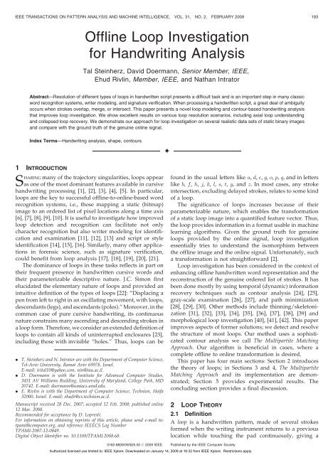
Fig. 1. Zoom-in on various patterns <strong>of</strong> alleged loops: (a) a real loop, where the area is not empty, i.e., there are background pixels inside the “hole;”<br />
(b) a large loop, where the area is empty, but the number <strong>of</strong> pixels on the perimeter is more than a threshold; (c) a small loop, where the area is<br />
empty and the number <strong>of</strong> pixels on the perimeter is less than or equal to a threshold; (d) the “lower limit” <strong>of</strong> a loop—an extremely thin loop that might<br />
be considered a pole because the top-down stroke completely overrides the bottom-up stroke it follows, leaving no theoretic “hole” in the middle.<br />
Light and dark gray squares illustrate the trajectory captured by a digitizer (online—determines the area and perimeter) and the image <strong>of</strong> scanning<br />
the associated inked page (<strong>of</strong>fline), respectively. Each square represents a single pixel. White lines represent the center mass <strong>of</strong> the pen tip<br />
movement.<br />
closed outline with a “hole” in the center. In this case, a<br />
stroke is a writing locus between every two consecutive local<br />
extremity points <strong>of</strong> the vertical dimension (y-axis).<br />
In practice, especially in low-resolution images, we<br />
require additional in<strong>for</strong>mation to distinguish a real authentic<br />
loop from a pair <strong>of</strong> two close, connected, and partially<br />
overlapping strokes. For this purpose, we define an<br />
authentic loop to be either real or large, where we have the<br />
following:<br />
. in a real loop, like the one presented in Fig. 1a, the<br />
area is not empty,<br />
. in a large loop, like the one shown in Fig. 1b, the area<br />
is empty, but the perimeter exceeds a predetermined<br />
threshold,<br />
where the area is the group <strong>of</strong> all background pixels inside<br />
the “hole” and the perimeter is the collection <strong>of</strong> <strong>for</strong>eground<br />
pixels surrounding it.<br />
However, Fig. 1c shows a shape that satisfies the<br />
definition <strong>of</strong> a loop but is rejected because it is too small.<br />
Patterns like the one illustrated in Fig. 1d are considered<br />
loops only when sufficiently large because they are rarely<br />
actual loops.<br />
2.2 Classification<br />
Let the axis be the main shortest path from the left side <strong>of</strong> the<br />
word to its right side, and let the tarsi be the remaining parts—<br />
ascenders and descenders. Then, based on J.C. Simon’s<br />
definition <strong>of</strong> a loop, we propose classification into two<br />
kinds:<br />
1. Natural loops, like the ones presented in Fig. 2,<br />
appear on tarsi and hence have a single anchor point<br />
where they hang on the axis.<br />
2. Artificial loops, like the ones shown in Fig. 3, partition<br />
the axis by presenting two interface points in diverse<br />
locations. The first interface point, on the left side, is<br />
the entrance, while the second one is the exit, hence<br />
it appears on the right side.<br />
2.3 Modeling<br />
We have developed two distinctive models that describe the<br />
two loop classes.<br />
A natural loop (Fig. 2) consists <strong>of</strong> a continuous pair <strong>of</strong><br />
consecutive strokes that surround an imaginary natural<br />
“hole.” All pairs <strong>of</strong> successive pixels by the temporal order<br />
are also 8-neighbors in the image domain. A bottom-up topdown<br />
pair <strong>of</strong> adjacent strokes sketches an ascending loop in<br />
a counterclockwise manner. A descending loop is drawn<br />
the other way around.<br />
An artificial loop (Fig. 3) occurs when two sets <strong>of</strong><br />
consecutive strokes introduce another contact point separate<br />
from their concatenation interface, sandwiching a<br />
blocked artificial “hole” between them. Either enclosing sets<br />
<strong>of</strong> consecutive strokes could be a natural subloop itself. The<br />
other alternatives are short poles or simple lines. The<br />
contact point could appear at the top or bottom <strong>for</strong> upper or<br />
lower artificial loops, respectively.<br />
An artificial loop is categorized according to its natural<br />
subloop (“hole”) configuration: neither side, only on the left<br />
side, only on the right side, both on the left and right sides.<br />
2.4 <strong>Offline</strong> versus Online<br />
In static (binary) images, the temporal in<strong>for</strong>mation is<br />
implicit and <strong>of</strong>ten ambiguous. When <strong>of</strong>fline processing<br />
occurs, visible “holes” appear as the only evidence that<br />
support allegedly genuine loop identification. Nevertheless,<br />
the abovementioned designation clearly displays that both<br />
types <strong>of</strong> loops present “holes,” so no isomorphism occurs<br />
Fig. 2. Two natural loops, each made <strong>of</strong> a single continuous chain <strong>of</strong><br />
consecutive strokes surrounding a “hole.” A bottom-up top-down pair <strong>of</strong><br />
adjacent strokes sketched in a counterclockwise manner <strong>for</strong>ms the<br />
ascending loop on the left. The descending loop on the right is drawn the<br />
other way around. Both loops have a single anchor point where they<br />
hang on the axis.<br />
Authorized licensed use limited to: IEEE Xplore. Downloaded on January 14, 2009 at 16:32 from IEEE Xplore. Restrictions apply.
STEINHERZ ET AL.: OFFLINE LOOP INVESTIGATION FOR HANDWRITING ANALYSIS 195<br />
Fig. 3. Four artificial loops, each created by two sets <strong>of</strong> consecutive<br />
strokes that introduce a separate contact point away from their<br />
concatenation interface, sandwiching a blocked artificial “hole” between<br />
them. The different loops suggest various alternatives <strong>of</strong> sets <strong>of</strong> stroke<br />
combinations: (a) two natural subloops (“holes”), (b) a pole and a natural<br />
subloop (“hole”), (c) a natural subloop (“hole”) and a simple line, and<br />
(d) two poles. In addition, the expected blocked artificial “hole” in (a) is<br />
not visible in the <strong>of</strong>fline representation. All loops partition the axis by<br />
presenting two interface points in diverse locations—the entrance and<br />
exit, on the left and right sides, respectively.<br />
between the collection <strong>of</strong> “holes” and one <strong>of</strong> the classes. The<br />
designation <strong>of</strong> axial and on-tarsus loops helps moderately<br />
but would not provide an indicative response <strong>for</strong> situations<br />
where multiambiguous “holes” are encapsulated within a<br />
single “frame” <strong>of</strong> an artificial (axial) loop. This happens<br />
when a natural subloop <strong>for</strong>mulates one <strong>of</strong> the “walls” that<br />
encloses the complete loop’s artificial “hole.” Furthermore,<br />
superfluous “holes” exist, like those in Figs. 4a and 4b,<br />
resulting from noisy pixels or remainders <strong>of</strong> traced-over<br />
natural subloops. There<strong>for</strong>e, general in<strong>for</strong>mation on “hole”<br />
inclusion or absence does not satisfactorily complete the<br />
categorization task, so the architecture <strong>of</strong> the presumed<br />
loop must be figured <strong>for</strong> each “hole” individually.<br />
In addition to uncertainties in the association <strong>of</strong> some<br />
observable “holes,” many others, both natural and artificial,<br />
collapse and become hidden in the transition to a static<br />
(binary) image <strong>for</strong>mat [40], [41], [42]. In this case, a blob<br />
remains in the original position <strong>of</strong> the genuine “hole.” This<br />
phenomenon results from blotting or blurring affects<br />
common to mechanical writing tools. Figs. 4c and 4d<br />
provides two examples <strong>of</strong> collapsed “holes,” a natural<br />
hidden loop and a natural hidden subloop on the left and<br />
right, respectively. Fig. 3a shows a collapsed artificial<br />
“hole.”<br />
Handwritten blobs also can be found in intersections <strong>of</strong><br />
strokes, junctions, and zones where consecutive strokes<br />
touch or partially override each other. In fact, previous<br />
studies showed that blob width could not distinguish the<br />
derivatives <strong>of</strong> genuine loops from the other byproducts [25],<br />
[41], [42], [43]. This task requires advanced shape analysis.<br />
In the context <strong>of</strong> loops, then, one must be able to identify<br />
and classify all authentic “holes” to bridge the gap between<br />
<strong>of</strong>fline and online and recover the topological structure <strong>of</strong> a<br />
loop. Complete identification requires recovery <strong>of</strong> collapsed<br />
“holes.” Successful classification means distinguishing<br />
between natural, artificial, and superfluous “holes” a<br />
posteriori.<br />
3 THE MULTIPARTITE MATCHING APPROACH<br />
3.1 Overview<br />
Originally, a single stroke in real time produces two<br />
contours on opposite sides, where a contour part is an<br />
ordered list <strong>of</strong> the minimum on-the-edge adjacent pixels.<br />
Usually, a contour piece would be located approximately<br />
half a stroke-width away from the exact position <strong>of</strong> the pen<br />
tip. Naturally, some valuable in<strong>for</strong>mation is lost in the<br />
transition to a static image representation. In this case, some<br />
contour pieces that cross have disappeared, others become<br />
difficult to sort because spatial connectivity is not isomorphic<br />
to the genuine temporal order, and the internal<br />
manner in which the pixels <strong>of</strong> a single piece are traversed<br />
(either <strong>for</strong>ward or backward) is not properly defined either.<br />
Two chains <strong>of</strong> concatenated matching contour pieces on<br />
opposite sides, which were created with a continuous set <strong>of</strong><br />
strokes and produced a single connectivity component, can<br />
be incorrectly represented by a static image. Specifically, the<br />
resulting static image presents a deceptively diverse picture<br />
<strong>of</strong> the contour. In this case, one element <strong>of</strong> the external<br />
contour exists, a single integrated portion <strong>of</strong> contour pieces<br />
that surrounds the whole body (one segment per connectivity<br />
component), and several elements <strong>of</strong> the internal<br />
Fig. 4. Two examples <strong>of</strong> superfluous “holes”: (a) the result <strong>of</strong> noisy pixel(s) and (b) traced-over legitimate natural subloop(s). Two examples <strong>of</strong><br />
collapsed “holes”: (c) natural ascending hidden loop and (d) natural ascending hidden subloop, featuring a left enclosing stroke in an artificial axial<br />
loop.<br />
Authorized licensed use limited to: IEEE Xplore. Downloaded on January 14, 2009 at 16:32 from IEEE Xplore. Restrictions apply.
196 IEEE TRANSACTIONS ON PATTERN ANALYSIS AND MACHINE INTELLIGENCE, VOL. 31, NO. 2, FEBRUARY 2009<br />
Fig. 5. The various contour sides <strong>of</strong> the word “flat”: (a) upper external, (b) lower external, and (c) internal.<br />
contours, a collection <strong>of</strong> contour fragments that surround<br />
each “hole.” Nevertheless, each and every visible contour<br />
piece derived from the static image is a genuine contour<br />
piece produced in real time.<br />
Normally, contour pieces <strong>of</strong> consecutive strokes also<br />
follow one another on the external edge <strong>of</strong> the resulting<br />
static image. One chain <strong>of</strong> concatenated contour pieces<br />
appears on the upper side <strong>of</strong> the external edge, while their<br />
complements appear on the lower side.<br />
However, abnormalities/singularities arise around junctions<br />
where two strokes intersect and cross each other. In<br />
this case, some contour pieces are covered and permanently<br />
lost, leaving an inked gap between pairs <strong>of</strong> consecutive<br />
contour parts. The neighbor <strong>of</strong> a contour piece at the<br />
intersection point does not actually follow it. Instead, the<br />
consecutive contour part would be found elsewhere along<br />
an edge <strong>of</strong> the resulting static image. Given the continuous<br />
nature <strong>of</strong> cursive handwriting, an intersection implies a<br />
close outline, i.e., a loop, so the next pieces <strong>of</strong> the contour on<br />
one side would appear inside the resulting “hole.” The<br />
contact between such allegedly neighboring contour pieces<br />
is referred to as a discontinuity point.<br />
As a first step toward regaining the separation to two<br />
distinguished sides, it is advisable to divide the external<br />
contour into upper and lower. Without limiting generality,<br />
the external contour begins at the original starting point<br />
chosen by the writer (up to an exact location on the<br />
perimeter <strong>of</strong> a loop). Likewise, one can presume the<br />
authentic final point. The original finishing point partitions<br />
the external contour into upper and lower: let the prefix up<br />
to the original finishing point constrain the upper external<br />
contour, and let the suffix from this point on describe the<br />
lower external contour. Pieces surrounding ascenders (descenders)<br />
can be further partitioned to left and right around<br />
the piece’s uppermost (lowermost) local maximum (minimum)<br />
point.<br />
Fig. 5 presents the external (upper þ lower) and internal<br />
contour pixels <strong>of</strong> the word “flat.”<br />
The Multipartite Matching Approach enables either the<br />
association <strong>of</strong> corresponding opposite-sided contour pieces<br />
or the validation <strong>of</strong> such a presumed matching hypothesis,<br />
to bridge/concatenate same-sided consecutive contour<br />
pieces across junctions, and to locate lost internal contours.<br />
Both opposite-sided contour piece association and lost<br />
internal contour location rely on measurements <strong>of</strong> mutual<br />
distances and shape similarity between contour pieces. Samesided<br />
consecutive contour piece bridging/concatenation<br />
across junctions use smoothness in slope/gradient<br />
changes and trend.<br />
The Multipartite Matching Approach utilizes a dual<br />
representation <strong>of</strong> contour pieces—pixel-based and sectionbased.<br />
In this case, a section is a short straight line that<br />
represents the smooth representation <strong>for</strong> the group <strong>of</strong><br />
consecutive pixels located in the interval between its<br />
starting and ending points. Above this, we develop a<br />
multilayer theory about inner and intercontour piece<br />
relations, derived from both representations in parallel—see<br />
the map in Fig. 6. The first level presents the basic attributes<br />
<strong>of</strong> an atomic entity—a single pixel or section, respectively.<br />
The second and third levels describe local and remote<br />
relations between pairs <strong>of</strong> touching and distant atomic<br />
entities, respectively, among which are turning angle and<br />
direction, distance, and shape similarity. The fourth level<br />
brings several operators that denote the existence <strong>of</strong><br />
association between pairs <strong>of</strong> atomic entities, the possibility<br />
<strong>of</strong> legal concatenation between pairs <strong>of</strong> atomic entities, and<br />
the prediction <strong>of</strong> whether a lost contour fragment occurs<br />
between two chains <strong>of</strong> consecutive atomic entities <strong>of</strong><br />
contour pieces.<br />
In the following sections, we elaborate on the labeling <strong>of</strong><br />
the various contour parts—upper, lower, left and right, the<br />
isomorphism between pixels and sections, and the four<br />
layers <strong>of</strong> in<strong>for</strong>mation derived from and computed based on<br />
contour representations.<br />
One may also refer to other papers that have suggested<br />
contour-based methods <strong>for</strong> various tasks in the document<br />
and handwriting processing and recognition fields [21],<br />
[25], [44].<br />
3.2 Representation<br />
Given a static image, the external contour is derived by<br />
surrounding the word’s body segment in a clockwise<br />
manner, keeping the neighboring background pixels to<br />
the left at all times, in a way that each on-the-edge pixel is<br />
visited at least once. In a similar way, each and every<br />
internal contour element is the collection <strong>of</strong> minimal<br />
ordered lists <strong>of</strong> on-the-edge adjacent pixels that surround<br />
a “hole” in the word’s image, given each on-the-edge pixel<br />
is visited at least once. Natural ascending (sub-)loops are<br />
surrounded in a counterclockwise manner. Similarly,<br />
natural descending (sub-)loops are surrounded in a clockwise<br />
manner. The method <strong>of</strong> surrounding artificial “holes”<br />
is not properly defined. Pixel adjacency occurs in accordance<br />
with the 8-neighbor rule. The white pixels in Fig. 7a<br />
Authorized licensed use limited to: IEEE Xplore. Downloaded on January 14, 2009 at 16:32 from IEEE Xplore. Restrictions apply.
STEINHERZ ET AL.: OFFLINE LOOP INVESTIGATION FOR HANDWRITING ANALYSIS 197<br />
Fig. 6. A diagram <strong>of</strong> the four layers <strong>of</strong> in<strong>for</strong>mation derived from the dual representation <strong>of</strong> contour pieces, pixel-based and section-based,<br />
respectively, including basic attributes, local and remote relations, and operators.<br />
Fig. 7. A zoom-in look on the external and internal contours <strong>of</strong> the character “a,” derived from the word “flat,” by pixel-based and section-based<br />
representations in (a) and (b), respectively. (c) An illustration <strong>of</strong> a contour section’s shape (its slant angle), turning angle and turning direction with the<br />
following one, and a beam <strong>of</strong> the projection coverage.<br />
represent the external and internal contours <strong>of</strong> the character<br />
“a,” derived from the word “flat.”<br />
In our view, a complementary functional representation<br />
<strong>for</strong> a piece <strong>of</strong> contour (other than an ordered list <strong>of</strong> adjacent<br />
pixels) is a set <strong>of</strong> concatenated sections, where each section<br />
is a (short) straight line that begins from and ends at a pixel<br />
<strong>of</strong> the genuine set. This representation appears as a<br />
smoothed version, based on the trade-<strong>of</strong>f <strong>of</strong> eliminating<br />
noise and significant but tiny fluctuations.<br />
Fig. 7b provides the equivalent section-based representation<br />
to the external and internal pixel-based contours <strong>of</strong> the<br />
character “a,” derived from the word “flat.”<br />
3.3 Isomorphism<br />
Section c ¼½p1;pnŠ—a straight line that connects p1 and pn is<br />
the smooth representation <strong>of</strong> an ordered list <strong>of</strong> neighboring<br />
pixels fp1; ...;png if and only if each one <strong>of</strong> the replaced<br />
pixels is located not more than 1 pixel (or some other<br />
predefined constant) away:<br />
kpi ck 1 1 i n; ð1Þ<br />
where the euclidean distance is the metric that measures the<br />
distance between a pixel and the straight line representing<br />
the section.<br />
The minimal set <strong>of</strong> concatenated sections fc1; ...;cMg ¼<br />
f½p1;begin;p1;endŠ; ...; ½pM;begin;pM;endŠg provides the isomorphic<br />
section-based representation <strong>for</strong> the pixel-based<br />
genuine <strong>for</strong>mat <strong>of</strong> a contour piece fp1; ...;pNg, where<br />
p1;begin ¼ p1 and pM;end ¼ pN if and only if<br />
pi;begin 2fp1; ...;pNg;pi;end 2fp1; ...;pNg; pi;end ¼ piþ1;begin<br />
1 i M and<br />
8pj 2fpi;begin; ...;pi;endg kpj cik 1 1 i M:<br />
ð2Þ<br />
See Fig. 7b <strong>for</strong> further illustration.<br />
3.4 Atomic Entities and Basic Attributes<br />
The atomic entity <strong>of</strong> the pixel-based <strong>for</strong>mat <strong>of</strong> a contour<br />
piece is one point represented by a two-dimensional vector:<br />
p ¼ðx; yÞ. Hence, the description <strong>of</strong> a pixel provides a single<br />
basic attribute—its location in the image space.<br />
The atomic entity <strong>of</strong> the section-based <strong>for</strong>mat <strong>of</strong> a contour<br />
piece is one short straight line represented by two enclosing<br />
pixels: c ¼½pbegin;pendŠ ¼½ðxbegin;ybeginÞ; ðxend;yendÞŠ. In this<br />
case, the description <strong>of</strong> a section provides several basic<br />
attributes—the location <strong>of</strong> all <strong>of</strong> its constituent pixels; and<br />
its shape given by the slant angle. See Fig. 7c <strong>for</strong> an<br />
Authorized licensed use limited to: IEEE Xplore. Downloaded on January 14, 2009 at 16:32 from IEEE Xplore. Restrictions apply.
198 IEEE TRANSACTIONS ON PATTERN ANALYSIS AND MACHINE INTELLIGENCE, VOL. 31, NO. 2, FEBRUARY 2009<br />
TABLE 1<br />
Basic Attributes <strong>of</strong> the Atomic Entities <strong>of</strong> Contour Representation<br />
TABLE 2<br />
Local Relations between the Atomic Entities <strong>of</strong> Contour Representation<br />
illustration <strong>of</strong> this. Table 1 summarizes the basic attributes<br />
<strong>of</strong> the atomic entities <strong>for</strong> both the pixel-based and sectionbased<br />
representations.<br />
3.5 Relations between Atomic Entities<br />
3.5.1 Local<br />
A building block <strong>of</strong> the pixel-based model <strong>of</strong> a contour<br />
piece represents the local relation between two adjacent<br />
pixels. Hence, the pair <strong>of</strong> pixels provides a joint attribute—one<br />
<strong>of</strong> eight possible turning directions in which the<br />
preceding pixel points to the one that follows in the ordered<br />
list. A building block <strong>of</strong> the section-based model <strong>of</strong> a<br />
contour piece is the local relation between two concatenated<br />
sections (at their interface point). In this case, the pair <strong>of</strong><br />
sections provides a joint attribute—the turning angle<br />
between the <strong>for</strong>mer and the subsequent in the set, given<br />
by subtraction <strong>of</strong> the current slant angle from the following<br />
one. See Fig. 7c <strong>for</strong> an illustration <strong>of</strong> this. The turning angle<br />
normalizes to the interval [0, ]. The sign <strong>of</strong> the turning<br />
angle, also referred to as the turning direction, is designated<br />
positive <strong>for</strong> left turns and negative <strong>for</strong> right ones. Table 2<br />
summarizes local relations between pairs <strong>of</strong> touching pixels<br />
and sections, respectively.<br />
3.5.2 Remote<br />
A building block <strong>of</strong> the pixel-based model <strong>of</strong> a contour<br />
piece is the remote relation between two pixels on opposite<br />
sides ({external versus internal} or {upper versus lower} or<br />
{left versus right}). Hence, the pair <strong>of</strong> pixels provides a joint<br />
attribute—their mutual Geodesic distance, defined as the<br />
minimum number <strong>of</strong> body pixels that separate the two<br />
body points. Fig. 11b illustrates a shortest Geodesic path<br />
that serves the distance calculation. Similarly, the distance<br />
between a pixel and a piece <strong>of</strong> contour is given by the<br />
minimum distance between the pixel and each one <strong>of</strong> the<br />
pixels on the other piece.<br />
A Breadth First Search (BFS) algorithm calculates the<br />
distance matrix between pairs <strong>of</strong> pixels on opposite sides.<br />
The search environment would be a graph isomorphic to<br />
the word’s image—inked pixels associated with nodes and<br />
8-neighboring relations represented by edges (see [45]).<br />
A building block <strong>of</strong> the section-based model <strong>of</strong> a contour<br />
piece is the remote relation between two sections on<br />
opposite sides. In this case, the pair <strong>of</strong> sections provides<br />
several joint attributes—their mutual distance, which is the<br />
minimal distance between a pair <strong>of</strong> pixels one from each<br />
section, their shape similarity given by the absolute difference<br />
between their slant angles, and their mutual projection<br />
coverage, which tests the potential <strong>of</strong> one section to cross the<br />
projection beam perpendicular to the other one (Fig. 7c),<br />
and vice versa.<br />
Table 3 summarizes remote relations between pairs <strong>of</strong><br />
distant pixels and sections, respectively.<br />
3.6 Operators on Atomic Entities<br />
3.6.1 Correspondence<br />
In our view, two pixels from contour pieces on opposite<br />
sides and that are near to one another may belong<br />
heuristically to the same genuine stroke. There<strong>for</strong>e, pixels<br />
pi and pj on opposite contour sides are presumed to be<br />
correspondence-based associated if and only if their mutual<br />
Geodesic distance does not equal more than the strokewidth:<br />
Correspondenceðpi;pjÞ ¼1<br />
iff P ixel Distanceðpi;pjÞ stroke-width:<br />
Authorized licensed use limited to: IEEE Xplore. Downloaded on January 14, 2009 at 16:32 from IEEE Xplore. Restrictions apply.<br />
ð3Þ
STEINHERZ ET AL.: OFFLINE LOOP INVESTIGATION FOR HANDWRITING ANALYSIS 199<br />
TABLE 3<br />
Remote Relations between the Atomic Entities <strong>of</strong> Contour Representation<br />
Fig. 8. (a) An illustration <strong>of</strong> all possible pairs <strong>of</strong> corresponding pieces within the external and internal contours and between the upper and lower sides<br />
<strong>of</strong> the external contour. (b) An illustration <strong>of</strong> all possible pairs <strong>of</strong> correlated sections within the external and internal contours and between the upper<br />
and lower sides <strong>of</strong> the external contour (pairs <strong>of</strong> parallel bars); two possible continuations between a section on the upper external contour and a<br />
section on the internal contour and between a section on the lower external contour and a section on the upper external contour (dashed lines); and<br />
all possible discontinuity points on the external contour (surrounding circles).<br />
One can propagate the correspondence property to a<br />
pixel-piece level as follows:<br />
Correspondenceðpi; fq1; ...;qngÞ<br />
¼ 1<br />
ð4Þ<br />
iff 9k 1 k n j Correspondenceðpi;qkÞ ¼1:<br />
Fig. 8a shows all possible pairs <strong>of</strong> corresponding pieces<br />
within the external and internal contours and between the<br />
upper and lower sides <strong>of</strong> the external contour.<br />
3.6.2 Correlation<br />
Two sections may heuristically belong to the same genuine<br />
stroke if they originate from contour pieces on opposite<br />
sides, present a similar shape, are not too far apart, and<br />
have a positive projection coverage potential. There<strong>for</strong>e,<br />
sections ca and cb on opposite contour sides are presumed to<br />
be correlation-based associated if and only if the absolute<br />
difference between their angles is less than or equal to pi<br />
over four, their mutual distance is less than or equal to<br />
twice the stroke-width, and there is at least one pixel on one<br />
section that crosses the projection beam <strong>of</strong> the other:<br />
Correlationðca;cbÞ ¼1 iffðSection Similarityðca;cbÞ =4Þ^<br />
ðSection Distanceðca;cbÞ 2 stroke-widthÞ^<br />
ððP rojection Coverageðca;cbÞ ¼1Þ_<br />
ðProjection Coverageðcb;caÞ ¼1ÞÞ:<br />
ð5Þ<br />
One can propagate the correlation property to a sectionpiece<br />
level as follows:<br />
Correlationðca; fd1; ...;dmgÞ ¼ 1<br />
ð6Þ<br />
iff 91 1 1 m j Correlationðca;dlÞ ¼1:<br />
Fig. 8b shows all possible pairs <strong>of</strong> correlated sections<br />
within the external and internal contours and between the<br />
upper and lower sides <strong>of</strong> the external contour.<br />
Authorized licensed use limited to: IEEE Xplore. Downloaded on January 14, 2009 at 16:32 from IEEE Xplore. Restrictions apply.
200 IEEE TRANSACTIONS ON PATTERN ANALYSIS AND MACHINE INTELLIGENCE, VOL. 31, NO. 2, FEBRUARY 2009<br />
Fig. 9. An illustration <strong>of</strong> the separation <strong>of</strong> an external contour fragment surrounding a collapsed “hole” to the left and right sides in (a) and (b),<br />
respectively. The graphs <strong>of</strong> the distance functions between left and right, and vice versa, in (c) top and bottom, respectively.<br />
3.6.3 Continuation<br />
The most common assumption about the oscillating hand<br />
movement when practicing cursive handwriting is that it acts<br />
under an objective to maintain smooth strokes as much as<br />
possible in order to lose as little energy as possible (Gestalt’s<br />
assumptions and parameters in [50]). In this case, one will<br />
refrain from sharp turns and avoid switches <strong>of</strong> the general<br />
trend from convex walk to concave, or vice versa, in the<br />
middle <strong>of</strong> a stroke. Instead, the same turning direction will<br />
appear all along the stroke. It seems that psychomotor factors<br />
relate to this behavior. This assumption was widely utilized<br />
in previous work (see, <strong>for</strong> example, [8], [25], and [28]).<br />
Based on this paradigm, we have heuristically determined<br />
that a newly created section that concatenates two<br />
pieces <strong>of</strong> contour into a single continuous stroke must<br />
preserve the same general trend <strong>of</strong> walk, either convex or<br />
concave, all the way from top to bottom, or vice versa,<br />
including the prefix <strong>of</strong> the originating piece <strong>of</strong> contour and<br />
the suffix <strong>of</strong> the destined one. From a practical standpoint,<br />
the turning direction at the interface points surrounding the<br />
newly created section must be preserved consistently.<br />
Hence, a newly <strong>for</strong>med section cnew ð¼ ½pa;end;pb;beginŠÞ<br />
creates a legitimate continuation (bridge)<br />
< ...;ca;cnew;cb; ...><br />
between two sections ca ð¼ ½pa;begin;pa;endŠÞ and cb ð¼<br />
½pb;begin;pb;endŠÞ on different sides <strong>of</strong> the contour around the<br />
same junction if and only if all the related turning directions<br />
(between the first and the newly <strong>for</strong>med sections, between<br />
the newly <strong>for</strong>med and second sections, in front <strong>of</strong> the first<br />
section, and behind the second section) are the same, and<br />
the newly <strong>for</strong>med section does not cross or get too close to<br />
background pixels, including “holes”:<br />
Continuationðca;cbÞ ¼1 iff ðturning directionðca;cnewÞ<br />
¼ turning directionðcnew;cbÞ<br />
¼ turning directionðca 1;caÞ ¼turning directionðcb;cbþ1ÞÞ<br />
^ðcnew is inside word 0 s bodyÞ:<br />
ð7Þ<br />
Fig. 8b presents two possible continuations by newly<br />
<strong>for</strong>med sections that concatenate a section on the upper<br />
external contour and a section on the internal contour <strong>of</strong> an<br />
encapsulated “hole,” and a section on the lower external<br />
contour and a section on the upper external contour.<br />
3.6.4 Discontinuity<br />
Continuing with the smooth path paradigm, we have<br />
heuristically determined that a switch <strong>of</strong> the turning<br />
direction trend far from an extremal point, which means a<br />
transition from convex to concave walk, or vice versa, or a<br />
sharp turn between two neighboring sections, may indicate<br />
the existence <strong>of</strong> a discontinuity point. The latter is a possible<br />
position <strong>for</strong> a contour split.<br />
The interface between two neighboring sections ca and caþ1<br />
is presumed to be a discontinuity point if and only if the turning<br />
direction is not the same as the turning direction between the<br />
first section and its predecessor, given neither the first nor the<br />
second section shares an extremal point, or the absolute<br />
turning angle is more than or equal to pi over two:<br />
Discontinuityðca;caþ1Þ ¼1 iffððturning directionðca;caþ1Þ<br />
6¼ turning directionðca 1;caÞÞ_<br />
ðturning angleðca;caþ1Þ > =2ÞÞ ^ ðpa;begin 6¼ extramum pointÞ<br />
^ðpaþ1;begin 6¼ extramum pointÞ:<br />
ð8Þ<br />
Fig. 8b shows all possible discontinuity points on the<br />
external contour.<br />
3.7 Computed Functions on Pieces <strong>of</strong> Contour<br />
3.7.1 Internal Contour Recovery<br />
Lacking a visible “hole,” a lost closed outline piece <strong>of</strong> an<br />
internal contour is characterized by the shape <strong>of</strong> a truncated<br />
ellipse with narrow waists—an aperture whose size approximates<br />
the stroke-width pixels at the origin, around the<br />
location <strong>of</strong> the genuine junction where the <strong>for</strong>egoing and<br />
backtracking strokes crossed each other. See, <strong>for</strong> example,<br />
the lost loop in Figs. 9a and 9b.<br />
Two pieces <strong>of</strong> contour on opposite sides <strong>of</strong> a blob that<br />
draw together an outline <strong>of</strong> an imaginary truncated ellipse<br />
Authorized licensed use limited to: IEEE Xplore. Downloaded on January 14, 2009 at 16:32 from IEEE Xplore. Restrictions apply.
STEINHERZ ET AL.: OFFLINE LOOP INVESTIGATION FOR HANDWRITING ANALYSIS 201<br />
Fig. 10. A flowchart <strong>of</strong> a complete loop investigation solution, including axial and on-tarsus loop analysis in general and recovery <strong>of</strong> hidden “holes” in<br />
particular.<br />
may heuristically indicate the existence <strong>of</strong> a lost piece <strong>of</strong> an<br />
internal contour surrounding a genuine “hole.”<br />
Let be the discrete function/vector <strong>of</strong><br />
the pixel-based distances between every pixel on one piece<br />
<strong>of</strong> contour fp1; ...;png and a second piece <strong>of</strong> contour<br />
fq1; ...;qmg on the opposite side, where 8i, 1 i n, Di ¼<br />
P ixel Distanceðpi; fq1; ...;qmgÞ: The two portions could<br />
enfold a natural “hole” if and only if a pixel exists on the<br />
first piece, <strong>for</strong> which the attached distance function/vector<br />
presents a substantial local minimum with respect to the<br />
distance values <strong>of</strong> the surrounding pixels. In this case, a<br />
substantial local minimum, used to reduce the effect <strong>of</strong><br />
natural gaps that emerge from normal quantization noise,<br />
means that either at least one pixel separates the local<br />
minimum and the local maximum that follows it or the<br />
difference between the values at these points is at least one.<br />
The distance values measured at the local minimum and<br />
maximum are required to be less than or equal to strokewidth<br />
and above stroke-width, respectively:<br />
Recoverðfp1; ...;png; fq1; ...;qmgÞ ¼ 1<br />
iff 9j i
202 IEEE TRANSACTIONS ON PATTERN ANALYSIS AND MACHINE INTELLIGENCE, VOL. 31, NO. 2, FEBRUARY 2009<br />
Fig. 11. (a) An illustration <strong>of</strong> the ascenders and descenders in the word “flat” following the separation <strong>of</strong> the axis parts. (b) A zoom-in illustration <strong>of</strong>an<br />
axial loop <strong>for</strong>mation <strong>of</strong> the character “a” by the concatenation (dashed lines) <strong>of</strong> a pair <strong>of</strong> matching ascender and descender (in white) and the<br />
suggested division mechanism <strong>of</strong> the area into quarters (full and semidashed white lines).<br />
ðCorrespondenceðpk; fq1; ...;qmgÞ ¼ 0Þ<br />
ð10Þ<br />
^ðj i stroke-widthÞ i k j;<br />
and the subset fqr; ...;qsg is a possible descender if and<br />
only if<br />
ðCorrespondenceðqt; fp1; ...;pngÞ ¼ 0Þ<br />
^ðs r stroke-widthÞ r t s:<br />
ð11Þ<br />
The remaining pixels on both sides <strong>of</strong> the external<br />
contour denote the axis parts.<br />
See Fig. 11a <strong>for</strong> a full illustration <strong>of</strong> the extracted<br />
ascenders and descenders in white. In this case, the<br />
stroke-width proportional threshold was five pixels.<br />
4.3 Forming Axial <strong>Loop</strong>s<br />
A pair <strong>of</strong> two matching opposite-sided tarsi on the upper<br />
and lower contours, an ascender and a descender, <strong>for</strong>ms an<br />
axial loop if and only if no proven axial substroke occurs<br />
between their roots on the axis. In this case, a proven axial<br />
substroke requires correspondence between pixels to the<br />
right <strong>of</strong> the ascender and others to the left <strong>of</strong> the descender,<br />
respectively, or vice versa. There<strong>for</strong>e, the ascender<br />
fpi; ...;pjg matches the descender fqr; ...;qsg <strong>for</strong> a common<br />
axial loop if and only if<br />
8k k
STEINHERZ ET AL.: OFFLINE LOOP INVESTIGATION FOR HANDWRITING ANALYSIS 203<br />
the descender half <strong>of</strong> the axial loop. The meaning <strong>of</strong><br />
association in this context denotes correspondence (Fig. 8a)<br />
and/or correlation (Fig. 8b) between the matching parts <strong>of</strong><br />
the internal and external contours at the pixel and/or<br />
section level, respectively. The complete natural subloop<br />
validation is given in Appendix A, which can be found on<br />
the Computer Society Digital Library at http://doi.ieee<br />
computersociety.org/10.1109/TPAMI.2008.68.<br />
4.6 Prioritizing Hypothesized Natural Subloops<br />
Given the artificial loop model, in which a natural subloop<br />
<strong>for</strong>ms one and only one <strong>of</strong> the loop’s enclosing walls, two or<br />
more hypothesized natural subloops cannot coexist when<br />
both associate with the same side <strong>of</strong> the hosting axial loop<br />
({left, right}) or share the same encapsulated “hole.” The<br />
complete natural subloop prioritization is given in Appendix<br />
B, which can be found on the Computer Society Digital<br />
Library at http://doi.ieeecomputersociety.org/10.1109/<br />
TPAMI.2008.68.<br />
4.7 Recovering Internal Hidden Subloops<br />
A hidden subloop encapsulated within an axial loop is<br />
recovered using the Recover function between the internal<br />
contour <strong>of</strong> a proven artificial “hole” and a related piece <strong>of</strong><br />
the surrounding external contour on the relevant <strong>of</strong> the four<br />
subsides ({upper, lower} X {left, right}). A hidden subloop<br />
would refer to every blob enfolded between matching<br />
pieces <strong>of</strong> the internal and external contour that <strong>of</strong>fer an<br />
internal contour recovery potential.<br />
Let f bottom; ...; topg be the set <strong>of</strong> pixels on the left<br />
or right side <strong>of</strong> the internal contour and let<br />
fpmatching bottom; ...;pmatching topg be the set <strong>of</strong> pixels on the<br />
matching nearest piece <strong>of</strong> external contour, then a hidden<br />
subloop exists between the two if and only if<br />
ðRecoverðf bottom;...; topg;f matching bottom;...; matching topgÞ¼1Þ_<br />
ðRecoverðf matching bottom;...; matching topg;f bottom;...; topgÞ¼1Þ:<br />
ð14Þ<br />
When investigating a vertical-oriented blob, it requires<br />
that ymatching bottom ¼ ybottom and ymatching top ¼ ytop; in case <strong>of</strong><br />
a horizontal-oriented blob, the x coordinates <strong>of</strong> the<br />
matching points prove identical.<br />
4.8 Recovering On-Tarsus Hidden <strong>Loop</strong>s<br />
An on-tarsus hidden loop is recovered using the Recover<br />
function between the left and right sides <strong>of</strong> the surrounding<br />
piece <strong>of</strong> external contour. A hidden subloop may refer to<br />
every tarsus with no visible “hole” that presents a recovery<br />
potential between its two sides.<br />
Let fppreceding extremity; ...;pboundaryg and fpboundaryþ1; ...;<br />
pfollowing extremityg be the sets <strong>of</strong> pixels on the left and right<br />
sides <strong>of</strong> the external contour surrounding a tarsus, where<br />
both pieces touch at one end (the boundary) and are trailed<br />
to the closest extremity points at the other end. A hidden<br />
natural loop exists between the two if and only if<br />
ðRecoverðfppreceding extremity; ...;pboundaryg;<br />
fpboundaryþ1; ...;pfollowing extremitygÞ ¼ 1Þ_<br />
ðRecoverðfpboundaryþ1; ...;pfollowing extremityg;<br />
fppreceding extremity; ...;pboundarygÞ ¼ 1Þ:<br />
ð15Þ<br />
In contrast to the preferred boundary between the left<br />
and right parts <strong>of</strong> a tarsus constructing an axial loop, the<br />
first alternative is not a discontinuity point but rather the<br />
presumed location <strong>of</strong> the end-point acting as the symmetry<br />
axis. Usually, this would be the top or bottom point <strong>for</strong><br />
ascender and descender, respectively. See Figs. 9a and 9b<br />
with the on-tarsus hidden loop, plus the left and right<br />
trailed sides <strong>of</strong> the surrounding contour.<br />
5 EXPERIMENTAL RESULTS<br />
5.1 Protocol<br />
We will evaluate the proposed loop investigation algorithm<br />
on three tasks that demonstrate the robustness <strong>of</strong> our<br />
algorithm to find the isomorphism between static images <strong>of</strong><br />
loops and the ground truth online trajectory. To continue<br />
our earlier analysis <strong>of</strong> this isomorphism, see Sections 1 and<br />
2, we have selected the following three key tasks:<br />
. classification <strong>of</strong> “holes” encapsulated in axial loops,<br />
. identification (recovery) <strong>of</strong> hidden natural loops<br />
located on tarsi, and<br />
. identification (recovery) <strong>of</strong> hidden natural subloops<br />
encapsulated in axial loops.<br />
The first task is equivalent to a full axial loop resolution<br />
because collapsed artificial “holes” can also be recovered in<br />
this way. The handwritten samples input <strong>for</strong> each experiment<br />
derived from images <strong>of</strong> pure cursive words, where<br />
loop investigation is highly crucial. The labeling process<br />
needed to create the ground truth <strong>for</strong> comparison purposes<br />
is labor intensive, so the amount <strong>of</strong> work that could be<br />
accomplished in a reasonable time has been limited. Under<br />
these circumstances, it is acceptable to test some aspects <strong>of</strong><br />
robustness by sharing the three evaluated tasks with two<br />
databases. In this way, both cross-database and cross-task<br />
within the same database comparisons were achieved. For<br />
example, in each <strong>of</strong> the two databases, the resolution <strong>of</strong> the<br />
images differed. As a result, the stroke-widths also differed.<br />
An extended session in which each experiment would be<br />
per<strong>for</strong>med on all the available data sets falls beyond the<br />
scope <strong>of</strong> this work. Nonetheless, this paper reports all the<br />
experiments conducted to test the abovementioned three<br />
tasks and does not filter inferior results.<br />
All thresholds either remain constant or vary in<br />
accordance with a single parameter—the stroke-width.<br />
The latter parameter is neither writer dependent nor word<br />
related. Instead, it is shared by all the images <strong>of</strong> a database<br />
and should be estimated only once per database. For this<br />
purpose, we select the most popular value <strong>of</strong> a histogram<br />
measuring the distances between pixels on the external and<br />
internal sides <strong>of</strong> the contour, respectively. Without limiting<br />
generality, any stroke-width dependent parameter may be<br />
fine-tuned by shifts <strong>of</strong> a few pixels—" < stroke-width. Ina<br />
similar way, negligible shifts <strong>of</strong> several degrees may occur<br />
in angle-oriented parameters. Eventually, a single fixed<br />
constant value will be established <strong>for</strong> each threshold per<br />
database. In this case, one may consider calculating the<br />
optimal value on a disjoint training set and applying it to<br />
the remaining test set.<br />
Authorized licensed use limited to: IEEE Xplore. Downloaded on January 14, 2009 at 16:32 from IEEE Xplore. Restrictions apply.
204 IEEE TRANSACTIONS ON PATTERN ANALYSIS AND MACHINE INTELLIGENCE, VOL. 31, NO. 2, FEBRUARY 2009<br />
5.2 Data<br />
5.2.1 Experiment 1: Encapsulated “Hole” Classification<br />
The experiment was conducted on 344 samples <strong>of</strong> the most<br />
frequent axial loop-oriented characters, o s and a s, that<br />
occurred in the middle <strong>of</strong> pure cursive words and did not<br />
suffer from unrelated noisy phenomena typical to first and<br />
last letters. All samples originated from the same directory<br />
<strong>of</strong> the IRONOFF database [47], which includes a significant<br />
collection <strong>of</strong> cursive words. Forty-seven writers penned<br />
1-20 words each. The IRONOFF database provides the<br />
online signal and a gray-scale image, taken simultaneously<br />
with the digitizing process, per sample. The <strong>of</strong>fline bitmap<br />
image representation was achieved by mapping all grayscale<br />
values below a selected threshold to 0, and all those<br />
above it to 1. The same threshold applied to all images in<br />
the database. This threshold was manually selected because<br />
it was an adaptation <strong>of</strong> the data to the required input <strong>for</strong>mat<br />
and not part <strong>of</strong> the tested algorithm. Strokes approximately<br />
five pixels wide were eventually achieved.<br />
The 344 samples contained 540 “holes” according to the<br />
following distribution: 287 natural, 241 artificial, and<br />
12 superfluous, see Figs. 3 and 4.<br />
Table 4 provides the distribution <strong>of</strong> the 344 axial loops as a<br />
function <strong>of</strong> our natural subloop configuration mentioned in<br />
Section 2 and with respect to the condition <strong>of</strong> the artificial<br />
“hole” {hidden, visible} that shared a common encapsulation.<br />
5.2.2 Experiment 2: Hidden <strong>Loop</strong> Identification<br />
The experiment was conducted on 1,273 pure cursive words<br />
taken from the Rumelhart’s data set [48], an extension <strong>of</strong> the<br />
HP data set found in the UNIPEN collection [49]. Six<br />
writers participated with 170–223 words each. In this case,<br />
the <strong>of</strong>fline bitmap image representation <strong>of</strong> a word was<br />
produced artificially by a linear concatenation <strong>of</strong> all<br />
neighboring pixels between every pair <strong>of</strong> pen-down, penup<br />
operations. Each line was three pixels thick on the<br />
average, so <strong>for</strong> every pixel along its central mass,<br />
approximately one pixel on each side appears along the<br />
gradient directions. Quantization aspects and intentional<br />
noise provided real conditions on the edges. See Fig. 12 <strong>for</strong><br />
illustration.<br />
Given a total number <strong>of</strong> 10,131 tarsi, 1,211 (12 percent)<br />
were found irrelevant as being part <strong>of</strong> an axial loop, and<br />
1,478 (14.6 percent) were disqualified because they had<br />
branches or were convex, i.e., twisted and ended away from<br />
the top or bottom point. Another 1,447 (14.3 percent) were<br />
uninteresting because they surrounded on-tarsus visible<br />
loops. Fig. 13 illustrates several examples <strong>for</strong> each one <strong>of</strong> the<br />
TABLE 4<br />
Axial <strong>Loop</strong> Distribution<br />
1 Including a single “hole” that shares both sides like an ascending\descending natural on-tarsus loop.<br />
abovementioned filtered tarsus types. The remaining<br />
5,995 tarsi were distributed as follows: 547 real hidden<br />
loops, 469 large hidden loops, and 4,979 poles (either small<br />
hidden loops or no loop), see Fig. 1.<br />
5.2.3 Experiment 3: Hidden Natural Subloop<br />
Identification<br />
A group <strong>of</strong> a-s acting as first letters was tested in the last<br />
experiment. The specific directory <strong>of</strong> the IRONOFF database<br />
[47] provided only a limited group <strong>of</strong> relevant words.<br />
Eventually, 95 words were collected from more than<br />
40 writers, who produced one to four samples each.<br />
Nevertheless, eight <strong>of</strong> these words were manually disqualified<br />
because they were ambiguous. In addition, some <strong>of</strong><br />
the remaining labels were overruled by our objective<br />
assessment <strong>of</strong> the true class that represents a given stroke<br />
(e.g., a very long hidden natural subloop that definitely<br />
stands <strong>for</strong> a pole). The remaining 87 letters were distributed<br />
between the two natural “hole”-less configurations: 51<br />
hidden loops and 36 poles, see Fig. 14.<br />
5.3 Results<br />
5.3.1 Experiment 1: Encapsulated “Hole” Classification<br />
Given 259 <strong>of</strong> 287 authentic natural subloops (90.2 percent)<br />
were successfully detected, false alarms happened in 18 <strong>of</strong><br />
253 (7.1 percent) instances, where authentic artificial or<br />
superfluous “holes” were mistakenly labeled as natural.<br />
Fig. 12. An illustration <strong>of</strong> the <strong>of</strong>fline bitmap image production: let the<br />
enumerated pixels in (a) be the discrete locations recorded by the<br />
digitizing tablet, then the thin trajectory in (b) would be the continuous<br />
online signal representation and the thick trajectory in (c) would be the<br />
artificial <strong>of</strong>fline representation.<br />
Authorized licensed use limited to: IEEE Xplore. Downloaded on January 14, 2009 at 16:32 from IEEE Xplore. Restrictions apply.
STEINHERZ ET AL.: OFFLINE LOOP INVESTIGATION FOR HANDWRITING ANALYSIS 205<br />
Fig. 13. Four types <strong>of</strong> tarsi that are filtered-out and not tested <strong>for</strong> exclusive hidden loops: part <strong>of</strong> an axial loop, with branches, convex (twists and ends<br />
away from the top or bottom point), and the surrounding <strong>of</strong> visible loops.<br />
This produces a total “hole” identification rate <strong>of</strong> 91.5 percent<br />
(494/540).<br />
The complete axial loop recognition rates appear in<br />
Table 5. In 80.2 percent <strong>of</strong> the axial loops, all encapsulated<br />
“holes” were classified properly and associated with the<br />
correct side.<br />
5.3.2 Experiment 2: Hidden <strong>Loop</strong> Identification<br />
Given 517 <strong>of</strong> 547 authentic real hidden loops (94.5 percent)<br />
and 341 <strong>of</strong> 469 authentic large hidden loops (72.7 percent)<br />
were successfully detected, false alarms happened in 563 <strong>of</strong><br />
4,979 (11.3 percent) instances, where authentic poles were<br />
mistakenly labeled as hidden loops. This produces a total<br />
concave tarsus classification rate <strong>of</strong> 88 percent (5,274/5,995).<br />
5.3.3 Experiment 3: Hidden Natural Subloop<br />
Identification<br />
Given 36 <strong>of</strong> 51 authentic hidden natural subloops (70.6 percent)<br />
were successfully detected, false alarms occurred in 10<br />
<strong>of</strong> 36 (27.8 percent) instances, where authentic poles were<br />
mistakenly labeled as hidden subloops. This produces a<br />
total nonquestionable stroke interpretation rate <strong>of</strong> 71.3 percent<br />
(62/87).<br />
Fig. 14. The two natural “hole”-less configurations <strong>of</strong> axial loops acting<br />
as first letter a-s. A hidden natural subloop <strong>for</strong>ms the right enclosing<br />
stroke <strong>of</strong> the artificial loop on the left. The loop on the right utilizes a pole<br />
type <strong>of</strong> enclosing right stroke.<br />
5.4 Discussion<br />
5.4.1 Experiment 1: Encapsulated “Hole” Classification<br />
Approximately one third <strong>of</strong> the misrecognized axial loops,<br />
6.4 percent, could not have been resolved by the proposed<br />
algorithm, because they do not behave according to the<br />
artificial loop paradigm and present twists in place <strong>of</strong><br />
continuous smooth strokes—see Figs. 15a and 15b. One<br />
particular writer produced most <strong>of</strong> these troublesome<br />
instances.<br />
In an additional 2.9 percent <strong>of</strong> the cases, the existing<br />
natural subloop could not have been designated by the<br />
proposed algorithm because the presumed continuation<br />
does not satisfy the smooth inclination condition.<br />
This extraordinary situation, illustrated in Fig. 15c,<br />
occurs when an unexpected sharp turn is made in the<br />
middle <strong>of</strong> the stroke. In this case, the assumption that one<br />
maintains smooth strokes to lose as little energy as possible<br />
(Section 3.6.3) was violated.<br />
Noise <strong>of</strong>fers explanation <strong>for</strong> the remaining portion <strong>of</strong><br />
failure cases. In 1.2 percent, the neighboring character<br />
attaches to the substantial side <strong>of</strong> the axial loop, shadowing<br />
the origination <strong>of</strong> the required continuation (concatenation).<br />
A similar phenomenon was observed in another 1.7 percent<br />
<strong>of</strong> the investigated loops, where extra ascenders exist<br />
between the natural subloop and the axis. See an exemplar<br />
in Fig. 15d.<br />
5.4.2 Experiment 2: Hidden <strong>Loop</strong> Identification<br />
A vast majority <strong>of</strong> the misdetections/false alarms relates to<br />
quantization difficulties that affect the visualization <strong>of</strong> large<br />
hidden loops in contrast with thin poles. Sometimes, similar<br />
circumstances cause confusion between a real hidden loop<br />
and a thick pole that has a trapeze shape. The trans<strong>for</strong>mation<br />
<strong>of</strong> a pair <strong>of</strong> true diagonal lines, denoting the left and<br />
right sides <strong>of</strong> the (external) contour <strong>of</strong> a tarsus, into two sets<br />
<strong>of</strong> discrete pixels is not well defined. As one can see in<br />
Fig. 16, two parallel lines, even those representing a cusp<br />
shape, could produce fluctuations in the mutual distance<br />
functions. As a result, hidden loops and poles can be<br />
substituted.<br />
Authorized licensed use limited to: IEEE Xplore. Downloaded on January 14, 2009 at 16:32 from IEEE Xplore. Restrictions apply.
206 IEEE TRANSACTIONS ON PATTERN ANALYSIS AND MACHINE INTELLIGENCE, VOL. 31, NO. 2, FEBRUARY 2009<br />
In some cases, the scanning and digitizing resolution<br />
fails to distinguish the actual hidden loops. In other words,<br />
the identified large hidden loops may have been perceived<br />
as real, i.e., with a visible “hole,” if the resolution was<br />
higher. The misrecognized hidden loops, however, are<br />
probably not actual. When the resolution increases, the<br />
signal-to-noise ratio <strong>of</strong> the Recover function can also be<br />
improved by demanding higher differences between the<br />
local minimum and maximum points. From a different<br />
point <strong>of</strong> view, 3.5 percent <strong>of</strong> the mistakenly recovered blobs<br />
contained small hidden loops that may be considered<br />
ambiguous.<br />
5.4.3 Experiment 3: Hidden Natural Subloop<br />
Identification<br />
In two <strong>of</strong> five misinterpreted loops, the reasons <strong>for</strong> failure<br />
match those <strong>of</strong> Experiment 2. However, most <strong>of</strong> the<br />
TABLE 5<br />
Complete Axial <strong>Loop</strong> Recognition Rates<br />
Fig. 15. Two misrecognized axial loops that do not behave according to the artificial loop paradigm: (a) and (b) the left stroke twists to the right and<br />
completes a natural subloop in a clockwise manner. Additional two groups <strong>of</strong> unresolved axial loops: (c) natural subloops with extraordinary<br />
de<strong>for</strong>mations caused by unexpected sharp turns in the middle <strong>of</strong> the constructing strokes and (d) natural subloops blocked between pairs <strong>of</strong><br />
substrokes, where one <strong>of</strong> each couple acts as an extra ascender that separates the “hole” from the axis. In both cases, a direct continuation cannot<br />
be presumed.<br />
Fig. 16. (a) A misdetected large hidden loop in comparison with a similar-looking pole. Both tarsi present matching staircases, with only one pixel<br />
difference in the mutual distances. Thus, both resemble a pole. (b) A false alarmed pole, mistakenly considered as hidden loop, in comparison with a<br />
similar-looking large hidden loop. Both tarsi present narrow waists that widen a few pixels away, giving the impression <strong>of</strong> an aperture behind a<br />
collapsed loop.<br />
confused strokes, approximately 16 percent <strong>of</strong> the error<br />
rate, concern bad handling <strong>of</strong> collisions between the origin<br />
<strong>of</strong> the left stroke and the body <strong>of</strong> the right one.<br />
Figs. 17a and 17b present two examples <strong>of</strong> misdetections,<br />
where the critical parts <strong>of</strong> a genuine hidden natural subloop<br />
were concealed. Figs. 17c and 17d illustrate the potential <strong>of</strong><br />
false alarms caused by interference <strong>of</strong> the other stroke.<br />
6 DISCUSSION<br />
We have proposed a novel contour-based handwriting<br />
analysis approach. The discussed method showed excellent<br />
results on various loop resolution scenarios, including axial<br />
loop understanding and collapsed loop recovery. Although<br />
we did not present experimental results that demonstrate<br />
the direct impact <strong>of</strong> our algorithm on word recognition and<br />
writer modeling systems, the theoretic analysis and<br />
Authorized licensed use limited to: IEEE Xplore. Downloaded on January 14, 2009 at 16:32 from IEEE Xplore. Restrictions apply.
STEINHERZ ET AL.: OFFLINE LOOP INVESTIGATION FOR HANDWRITING ANALYSIS 207<br />
Fig. 17. Characteristic misinterpreted axial loops in the letter a at the beginning <strong>of</strong> a word: (a) a misdetection caused by the other stroke overwriting<br />
the aperture; (b) a misdetection that occurred when the attempt to detach the left and right strokes (see the crossing line) failed to preserve the<br />
original shape <strong>of</strong> the latter—as a result, no hints <strong>of</strong> a hidden natural subloop were found in the remaining blob; (c) an example <strong>of</strong> a misleading<br />
intersection between the left and right strokes, resulting in a false alarm—a cusp-shaped pole creates an illusion <strong>of</strong> a hidden natural subloop because<br />
the attached stroke <strong>for</strong>ces narrow waists on the internal contour; and (d) another false alarm that happened when the tail <strong>of</strong> the left stroke was not<br />
eliminated properly, leaving behind a false local minimum point in the distance functions between the internal and external contours.<br />
supporting references we described <strong>of</strong>fer ample evidence <strong>of</strong><br />
the importance <strong>of</strong> loop interpretation as a preprocessing<br />
step in such applications. In this case, when utilizing the<br />
suggested method, one may be provided with additional<br />
valuable in<strong>for</strong>mation that may distinguish among loopbased<br />
handwritten patterns that appear similar in their<br />
topological and geometrical structure in advance.<br />
Furthermore, we found strong evidence that loop understanding<br />
supports character recognition. In this case, we<br />
learned that the frequency <strong>of</strong> some common structures<br />
changes dramatically between letters. Writer identification/<br />
verification is supported similarly by the proposed algorithm,<br />
given that the correspondence between writers and<br />
styles <strong>of</strong> loops is high. The robustness <strong>of</strong> the proposed<br />
algorithm was demonstrated using two databases that<br />
provided samples in different resolutions and strokewidths.<br />
In particular, the method demonstrated its practicality<br />
<strong>for</strong> use with low-resolution images.<br />
Future work would generalize the suggested method<br />
and expand the framework <strong>of</strong> events that can be treated.<br />
Improved recovery capabilities can be achieved by utilizing<br />
the preliminary dehooking technique that was partially<br />
practiced and discussed in the context <strong>of</strong> the hidden natural<br />
subloop identification on the first letter a-s. In that way,<br />
subbranches, like the two sides <strong>of</strong> a t-bar, might be filtered.<br />
For the same purpose, it would be beneficial to have the<br />
ability <strong>of</strong> tracing genuine end-points that are neither the<br />
uppermost nor the lowermost pixels in order to handle<br />
convex tarsi such as c-strokes and open s-s. A complete<br />
implementation <strong>of</strong> this approach to the beginning and<br />
ending letters <strong>of</strong> a word also requires an adaptation <strong>of</strong> the<br />
axial loop model in addition to the abovementioned<br />
dehooking preprocess.<br />
The presented algorithm is highly relevant to other tasks<br />
and applications in the field <strong>of</strong> handwriting analysis. We<br />
strongly believe the advanced tools developed here, along<br />
with the contour-based concept and guidelines, may prove<br />
useful in other fields <strong>of</strong> logical image understanding, where<br />
one can define a set <strong>of</strong> constraining rules on the visible<br />
edges and their interconnections. Examples could include<br />
medical visualizations, urban landscape interpretation, and<br />
automatic target recognition.<br />
REFERENCES<br />
[1] J.C. Simon and O. Baret, “Regularities and Singularities in Line<br />
Pictures,” Int’l J. Pattern Recognition and Artificial Intelligence, vol. 5,<br />
nos. 1-2, pp. 57-77, 1991.<br />
[2] R. Plamondon and S.N. Srihari, “On-Line and Off-Line <strong>Handwriting</strong><br />
Recognition: A Comprehensive Survey,” IEEE Trans.<br />
Pattern <strong>Analysis</strong> and Machine Intelligence, vol. 22, no. 1, pp. 63-84,<br />
Jan. 2000.<br />
[3] A. Vinciarelli, “A Survey on Off-Line Cursive Word Recognition,”<br />
Pattern Recognition, vol. 35, no. 7, pp. 1433-1446, 2002.<br />
[4] T. Steinherz, E. Rivlin, and N. Intrator, “Off-Line Cursive Script<br />
Word Recognition—A Survey,” Int’l J. Document <strong>Analysis</strong> and<br />
Recognition, vol. 2, nos. 2-3, pp. 90-110, 1999.<br />
[5] L. Schomaker and E. Segers, “Finding Features Used in the<br />
Human Reading <strong>of</strong> Cursive <strong>Handwriting</strong>,” Int’l J. Document<br />
<strong>Analysis</strong> and Recognition, vol. 2, nos. 2-3, pp. 13-18, 1999.<br />
[6] V. Govindaraju and R.K. Krishnamurthy, “Holistic Handwritten<br />
Word Recognition Using Temporal Features Derived from Off-<br />
Line Images,” Pattern Recognition Letters, vol. 17, no. 5, pp. 537-540,<br />
1996.<br />
[7] V. Govindaraju, D. Wang, and S.N. Srihari, “Using Temporal<br />
In<strong>for</strong>mation in Off-Line Word Recognition,” Proc. US Postal Service<br />
Fifth Advanced Technology Conf., pp. 529-543, 1992.<br />
[8] P.M. Lallican, C. Viard-Gaudin, and S. Knerr, “From Off-Line to<br />
On-Line <strong>Handwriting</strong> Recognition,” Proc. Int’l Workshop Frontiers<br />
in <strong>Handwriting</strong> Recognition, pp. 303-312, 2000.<br />
[9] H. Bunke, M. Roth, and E.G. Schukat-Talamazzini, “Off-Line<br />
Cursive <strong>Handwriting</strong> Recognition Using Hidden Markov Models,”<br />
Pattern Recognition, vol. 28, no. 9, pp. 1399-1413, 1995.<br />
[10] H. Bunke, M. Roth, and E.G. Schukat-Talamazzini, “Off-Line<br />
Recognition <strong>of</strong> Cursive Script Produced by a Cooperative Writer,”<br />
Proc. Int’l Conf. Pattern Recognition, pp. 383-386, 1994.<br />
[11] S.N. Srihari and Z. Shi, “Forensic Handwritten Document<br />
Retrieval System,” Proc. Int’l Workshop Document Image <strong>Analysis</strong><br />
<strong>for</strong> Libraries, pp. 188-194, 2004.<br />
[12] K. Frank, L.R.B. Schomaker, C. Veenhuis, L.G. Vuurpijl, M. Van<br />
Erp, and I. Guyon, “WANDA: A Common Ground <strong>for</strong> Forensic<br />
<strong>Handwriting</strong> Examination and Writer Identification,” ENFHEX<br />
News—Bull. European Network <strong>of</strong> Forensic <strong>Handwriting</strong> Experts,<br />
vol. 1, pp. 23-47, 2004.<br />
[13] C. Hertel and H. Bunke, “A Set <strong>of</strong> Novel Features <strong>for</strong> Writer<br />
Identification,” Proc. Int’l Conf. Audio- and Video-Based Biometric<br />
Person Authentication, pp. 679-687, 2003.<br />
[14] J. Hochberg, K. Bowers, M. Cannon, and P. Kelly, “Script and<br />
Language Identification <strong>for</strong> Handwritten Document Images,” Int’l<br />
J. Document <strong>Analysis</strong> and Recognition, vol. 2, nos. 2-3, pp. 45-52,<br />
1999.<br />
[15] N.E. Ben Amara and F. Bouslama, “Classification <strong>of</strong> Arabic Script<br />
Using Multiple Sources <strong>of</strong> In<strong>for</strong>mation: State <strong>of</strong> the Art and<br />
Perspectives,” Int’l J. Document <strong>Analysis</strong> and Recognition, vol. 5,<br />
no. 4, pp. 195-212, 2003.<br />
[16] L. Vuurpijl and L.R.B. Schomaker, “Coarse Writing-Style Clustering<br />
Based on Simple Stroke-Related Features,” Proc. Int’l Workshop<br />
Frontiers in <strong>Handwriting</strong> Recognition, pp. 29-32, 1996.<br />
Authorized licensed use limited to: IEEE Xplore. Downloaded on January 14, 2009 at 16:32 from IEEE Xplore. Restrictions apply.
208 IEEE TRANSACTIONS ON PATTERN ANALYSIS AND MACHINE INTELLIGENCE, VOL. 31, NO. 2, FEBRUARY 2009<br />
[17] K. Han and I.K. Sethi, “Handwritten Signature Retrieval and<br />
Identification,” Pattern Recognition Letters, vol. 7, no. 1, pp. 83-90,<br />
1996.<br />
[18] V.S. Nalwa, “Automatic On-Line Signature Verification,” Proc.<br />
IEEE, vol. 85, no. 2, pp. 215-239, 1997.<br />
[19] R. Sabourin, J.P. Drouhard, and E.S. Wah, “Shape Matrices as a<br />
Mixed Shape Factor <strong>for</strong> Off-Line Signature Verification,” Proc. Int’l<br />
Conf. Document <strong>Analysis</strong> and Recognition, pp. 661-665, 1997.<br />
[20] R. Sabourin, “Off-Line Signature Verification: Recent Advances<br />
and Perspectives,” Proc. Brazilian Symp. Document Image <strong>Analysis</strong>,<br />
pp. 84-98, 1997.<br />
[21] S. Chen and S.N. Srihari, “Use <strong>of</strong> Exterior Contours and Word<br />
Shape in Off-Line Signature Verification,” Proc. Int’l Conf.<br />
Document <strong>Analysis</strong> and Recognition, pp. 1280-1284, 2005.<br />
[22] J.C. Simon, “Off-Line Cursive Word Recognition,” Proc. IEEE,<br />
vol. 80, no. 7, pp. 1150-1161, 1992.<br />
[23] R.G.J. Meulenbroek, A.J.W.M. Thomassen, P.H.H.M. van Lieshout,<br />
and S.P. Swinnen, “The Stability <strong>of</strong> Pen-Joint and Interjoint<br />
Coordination in <strong>Loop</strong> Writing,” Acta Psychologica, vol. 100, nos. 1-<br />
2, pp. 55-70, 1998.<br />
[24] G. Boccignone, A. Chianese, L.P. Cordella, and A. Marcelli,<br />
“Recovering Dynamic In<strong>for</strong>mation from Static <strong>Handwriting</strong>,”<br />
Pattern Recognition, vol. 26, no. 3, pp. 409-418, 1993.<br />
[25] R. Plamondon and C.M. Privitera, “The Segmentation <strong>of</strong> Cursive<br />
<strong>Handwriting</strong>: An Approach Based on Off-Line Recovery <strong>of</strong> the<br />
Motor-Temporal In<strong>for</strong>mation,” IEEE Trans. Image Processing,<br />
vol. 8, no. 1, pp. 80-91, 1999.<br />
[26] D.S. Doermann and A. Rosenfeld, “Recovery <strong>of</strong> Temporal<br />
In<strong>for</strong>mation from Static Images <strong>of</strong> <strong>Handwriting</strong>,” Int’l J. Computer<br />
Vision, vol. 15, nos. 1-2, pp. 143-164, 1995.<br />
[27] D.S. Doermann and A. Rosenfeld, “The Interpretation and<br />
Reconstruction <strong>of</strong> Inferring Strokes,” Proc. Int’l Workshop Frontiers<br />
in <strong>Handwriting</strong> Recognition, pp. 41-50, 1993.<br />
[28] S. Jaeger, “On the Complexity <strong>of</strong> Cognition,” Proc. Int’l Workshop<br />
Frontiers in <strong>Handwriting</strong> Recognition, pp. 291-302, 2000.<br />
[29] Y. Kato and M. Yasuhara, “Recovery <strong>of</strong> Drawing Order from<br />
Single-Stroke <strong>Handwriting</strong> Images,” IEEE Trans. Pattern <strong>Analysis</strong><br />
and Machine Intelligence, vol. 22, no. 9, pp. 938-949, Sept. 2000.<br />
[30] Y. Qiao, M. Nishiara, and M. Yasuhara, “A Novel Approach to<br />
Recover Writing Order from Single Stroke <strong>Offline</strong> Handwritten<br />
Images,” Proc. Int’l Conf. Document <strong>Analysis</strong> and Recognition,<br />
pp. 227-231, 2005.<br />
[31] T.S. Cheng, C. Chiang, S.M. Roan, and H.C. Fu, “Feature-<br />
Preserving Thinning Algorithm <strong>for</strong> Optical Character Recognition,”<br />
Proc. SPIE—Character Recognition Technologies, pp. 279-290,<br />
1993.<br />
[32] L. Lam, S.W. Lee, and C.Y. Suen, “Thinning Methodologies: A<br />
Comprehensive Survey,” IEEE Trans. Pattern <strong>Analysis</strong> and Machine<br />
Intelligence, vol. 14, no. 9, pp. 869-885, Sept. 1992.<br />
[33] B.K. Jang and R.T. Chin, “<strong>Analysis</strong> <strong>of</strong> Thinning Algorithms Using<br />
Math. Morphology,” IEEE Trans. Pattern <strong>Analysis</strong> and Machine<br />
Intelligence, vol. 12, no. 6, pp. 541-551, June 1990.<br />
[34] T. Caesar, J. Gloger, A. Kaitenmeier, and E. Mandler, “Recognition<br />
<strong>of</strong> <strong>Handwriting</strong> Word Images by Statistical Methods,” Proc. Int’l<br />
Workshop Frontiers in <strong>Handwriting</strong> Recognition, pp. 409-416, 1993.<br />
[35] L. Lam and C.Y. Suen, “An Evaluation <strong>of</strong> Parallel Thinning<br />
Algorithms <strong>for</strong> Character Recognition,” IEEE Trans. Pattern<br />
<strong>Analysis</strong> and Machine Intelligence, vol. 17, no. 9, pp. 914-919, Sept.<br />
1995.<br />
[36] R. Plamondon, M. Bourdeau, C. Chouinard, and C.Y. Suen,<br />
“Validation <strong>of</strong> Preprocessing Algorithms: A Methodology and Its<br />
Application to the Design <strong>of</strong> a Thinning Algorithm <strong>for</strong> <strong>Handwriting</strong><br />
Characters,” Proc. Int’l Conf. Document <strong>Analysis</strong> and<br />
Recognition, pp. 262-269, 1993.<br />
[37] R. Plamondon, C.Y. Suen, M. Bourdeau, and C. Barriere,<br />
“Methodologies <strong>for</strong> Evaluating Thinning Algorithms <strong>for</strong> Character<br />
Recognition,” Int’l J. Pattern Recognition and Artificial<br />
Intelligence, vol. 7, no. 5, pp. 1247-1270, 1993.<br />
[38] T. Steinherz, N. Intrator, and E. Rivlin, “A Special Skeletonization<br />
Algorithm <strong>for</strong> Cursive Words,” Proc. Int’l Workshop Frontiers in<br />
<strong>Handwriting</strong> Recognition, pp. 529-534, 2000.<br />
[39] J.C. Pettier and J. Camillerapp, “Script Representation by a<br />
Generalized Skeleton,” Proc. Int’l Conf. Document <strong>Analysis</strong> and<br />
Recognition, pp. 850-853, 1993.<br />
[40] V. Pervouchine, G. Leedham, and K. Melikhov, “Three-Stage<br />
<strong>Handwriting</strong> Stroke Extraction Method with Hidden <strong>Loop</strong><br />
Recovery,” Proc. Int’l Conf. Document <strong>Analysis</strong> and Recognition,<br />
pp. 307-311, 2005.<br />
[41] I.S.I. Abuhaiba, M.J.J. Holt, and S. Datta, “Processing <strong>of</strong> Binary<br />
Images <strong>of</strong> Handwritten Text Documents,” Pattern Recognition,<br />
vol. 29, no. 7, pp. 1161-1177, 1996.<br />
[42] I.S.I. Abuhaiba, S. Datta, and M.J.J. Holt, “Processing <strong>of</strong> Text<br />
Documents: Straight Line Approximation and Lost <strong>Loop</strong> Recovery,”<br />
Proc. Int’l Conf. Document <strong>Analysis</strong> and Recognition, pp. 1157-<br />
1160, 1995.<br />
[43] D.S. Doermann, “Document Image Understanding: Integrating<br />
Recovery and Interpretation,” PhD dissertation, Univ. <strong>of</strong> Maryland,<br />
1993.<br />
[44] S. Madhvanath, G. Kim, and V. Govindaraju, “Chaincode Contour<br />
Processing <strong>for</strong> Handwritten Word Recognition,” IEEE Trans.<br />
Pattern <strong>Analysis</strong> and Machine Intelligence, vol. 21, no. 9, pp. 928-<br />
932, Sept. 1999.<br />
[45] T. Steinherz, E. Rivlin, N. Intrator, and P. Neskovic, “An<br />
Integration <strong>of</strong> Online and Pseudo-Online In<strong>for</strong>mation <strong>for</strong> Cursive<br />
Word Recognition,” IEEE Trans. Pattern <strong>Analysis</strong> and Machine<br />
Intelligence, vol. 27, no. 5, pp. 669-683, May 2005.<br />
[46] D.S. Doermann, N. Intrator, E. Rivlin, and T. Steinherz, “Hidden<br />
<strong>Loop</strong> Recovery <strong>for</strong> <strong>Handwriting</strong> Recognition,” Proc. Int’l Workshop<br />
Frontiers in <strong>Handwriting</strong> Recognition, pp. 375-380, 2002.<br />
[47] C. Viard-Gaudin, P.M. Lallican, S. Knerr, and P. Binter, “The<br />
IRESTE On/Off (IRONOFF) Dual <strong>Handwriting</strong> Database,” Proc.<br />
Int’l Conf. Document <strong>Analysis</strong> and Recognition, pp. 455-458, 1999.<br />
[48] D.E. Rumelhart, “Theory to Practice: A Case Study—Recognizing<br />
Cursive <strong>Handwriting</strong>,” Computational Learning and Cognition: Proc.<br />
Third NEC Research Symp., pp. 177-196, 1993.<br />
[49] I. Guyon, L. Schomaker, R. Plamondon, M. Liberman, and S. Janet,<br />
“Unipen Project <strong>of</strong> On-Line Data Exchange and Recognizer<br />
Benchmarks,” Proc. Int’l Conf. Pattern Recognition, pp. 29-33, 1994.<br />
[50] D.K.W. Walters, “Selection <strong>of</strong> Image Primitives <strong>for</strong> General-<br />
Purpose Visual Processing,” Computer Vision, Graphics, and Image<br />
Processing, vol. 37, no. 2, pp. 261-298, 1987.<br />
Tal Steinherz received the BSc degree in<br />
mathematics, physics, and computer science<br />
from the Hebrew <strong>University</strong>, Jerusalem, and the<br />
PhD degree in computer science from Tel-Aviv<br />
<strong>University</strong>. His research interests are online and<br />
<strong>of</strong>fline cursive word processing and recognition,<br />
document analysis, and writer models.<br />
David Doermann received the BSc degree in<br />
computer science and mathematics from<br />
Bloomsburg <strong>University</strong> in 1987 and the MSc<br />
and PhD degrees from the <strong>University</strong> <strong>of</strong> Maryland,<br />
College Park, in 1989 and 1993, respectively.<br />
Since 1993, he has served as a codirector<br />
<strong>of</strong> the Laboratory <strong>for</strong> Language and Media<br />
Processing, Institute <strong>for</strong> Advanced Computer<br />
Studies, <strong>University</strong> <strong>of</strong> Maryland, and as an<br />
adjunct member <strong>of</strong> the graduate faculty. His<br />
team <strong>of</strong> 15-20 researchers focuses on topics related to document image<br />
analysis and multimedia in<strong>for</strong>mation processing. His recent intelligent<br />
document image analysis projects include page decomposition, structural<br />
analysis and classification, page segmentation, logo recognition,<br />
document image compression, duplicate document image detection,<br />
image-based retrieval, character recognition, generation <strong>of</strong> synthetic<br />
OCR data, and signature verification. In video processing, his projects<br />
have centered on the segmentation <strong>of</strong> compressed domain video<br />
sequences, structural representation and classification <strong>of</strong> video, detection<br />
<strong>of</strong> re<strong>for</strong>matted video sequences, and the per<strong>for</strong>mance evaluation <strong>of</strong><br />
automated video analysis algorithms. He is a coeditor <strong>of</strong> the International<br />
Journal on Document <strong>Analysis</strong> and Recognition. He has more<br />
than 25 journal and almost 100 refereed conference proceedings<br />
publications. He is a senior member <strong>of</strong> the IEEE and a member <strong>of</strong> the<br />
IEEE Computer Society.<br />
Authorized licensed use limited to: IEEE Xplore. Downloaded on January 14, 2009 at 16:32 from IEEE Xplore. Restrictions apply.
STEINHERZ ET AL.: OFFLINE LOOP INVESTIGATION FOR HANDWRITING ANALYSIS 209<br />
Ehud Rivlin received the BSc and MSc<br />
degrees in computer science and the MBA<br />
degree from the Hebrew <strong>University</strong>, Jerusalem,<br />
and the PhD degree from the <strong>University</strong> <strong>of</strong><br />
Maryland. He is currently a pr<strong>of</strong>essor in the<br />
Computer Science Department at the Technion-<br />
Israel Institute <strong>of</strong> Technology. His current<br />
research interests are in machine vision and<br />
robot navigation. He is a member <strong>of</strong> the IEEE.<br />
Nathan Intrator received the PhD degree in<br />
applied mathematics from Brown <strong>University</strong>. He<br />
is currently with the School <strong>of</strong> Computer Science<br />
at Tel-Aviv <strong>University</strong>. His research interests<br />
include statistical and machine learning, methods<br />
<strong>for</strong> feature extraction, robust classification,<br />
and fusion from multiple experts. In addition, he<br />
studies signal processing methods under very<br />
noisy environment, with specific application to<br />
biomedical signals and brain imaging. He is a<br />
coauthor <strong>of</strong> the book Theory <strong>of</strong> Cortical Plasticity, which describes a<br />
connection between robust statistics and a neural learning rule, which<br />
he studied in the past. He is the author <strong>of</strong> more than 50 scientific journal<br />
publications, 50 peer reviewed conference proceedings, and 10 patent<br />
applications. Most <strong>of</strong> his publications can be found online at<br />
www.cs.tau.ac.il/~nin.<br />
. For more in<strong>for</strong>mation on this or any other computing topic,<br />
please visit our Digital Library at www.computer.org/publications/dlib.<br />
Authorized licensed use limited to: IEEE Xplore. Downloaded on January 14, 2009 at 16:32 from IEEE Xplore. Restrictions apply.