

data center interconnections - The Cisco Learning Network
data center interconnections - The Cisco Learning Network
data center interconnections - The Cisco Learning Network

Create successful ePaper yourself
Turn your PDF publications into a flip-book with our unique Google optimized e-Paper software.
To “capture” the traffic, the same mechanisms are used in this system as with L2TP: xconnect. Only the<br />
encapsulation is different (MPLS instead of IP).<br />
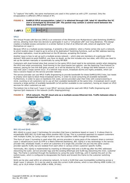
FIGURE 4: EoMPLS/VPLS encapsulation. Label L1 is obtained through LDP, label V1 identifies the VC<br />
and is exchanged by Directed LDP. <strong>The</strong> packet may contain a control word between the<br />
labels and the actual frame.<br />
VPLS<br />
<strong>The</strong> Virtual Private LAN Service (VPLS) is an extension of the Ethernet over Multiprotocol Label Switching (EoMPLS)<br />
service, allowing more than two devices to participate in such a “virtualized LAN” over long distances. This design<br />
creates a multiple-access connection in a similar fashion to that of an Ethernet LAN, where all segments “see”<br />
themselves on Layer 2.<br />
Because VPLS is a multiple-access topology, it presents a few problems: when a frame comes into such a network,<br />
to which location does it need to go to arrive at its destination? Switching functions, such as MAC address learning<br />
and frame replication, must be performed on the PE devices, accepting the frames.<br />
Another issue is how to set up such a multiple-access network – which sites are members of a particular VPLS<br />
domain? With point-to-point EoMPLS, you have no doubt, as the link includes only two sites; with VPLS you need to<br />
set up the domain manually or dynamically by using MP-BGP.<br />
Customers with dual-homed sites that connect to the same VPLS cloud need to be extremely careful when designing<br />
the VPLS and when provisioning. Dual-homing to the cloud leaves two options: use the Spanning Tree Protocol (in<br />
essence, paying for one link that goes unused, as it will be blocked by STP), or design the WAN network in such a<br />
way that Layer 2 loops cannot occur. If a network loop occurs, broadcast storms are highly probable, which can<br />
have a severe impact on the service provider network.<br />
<strong>The</strong> service provider can use MPLS Traffic Engineering to provide bandwidth for these EoMPLS/VPLS links, but needs<br />
to employ strict QoS to block these broadcast storms, in order to avoid consuming all available bandwidth.<br />
Furthermore, in order to save on backbone link costs, service providers plan their links with overprovisioning in<br />
mind, counting on all customers not to use all their available bandwidth at the same time. A broadcast storm would<br />
consume a large portion of available bandwidth (a full portion available to one customer), having an impact on VPLS<br />
services for other customers as well.<br />
<strong>The</strong> bottom line is that such “Layer-2 over MPLS” services should be used with MPLS Traffic Engineering and<br />
rigorous QoS measures in the network (traffic shaping/policing).<br />
FIGURE 5: VPLS network. <strong>The</strong> SP cloud acts as a multiple access Ethernet link. Traffic between sites is<br />
transported using MPLS.<br />
802.1Q and QinQ<br />
802.1QinQ is a pure Layer 2 technology for providers that have a backbone based on Layer 2. It allows them to<br />
encapsulate IEEE 802.1Q VLAN tags within another 802.1Q tag. This is a practical approach to support customers<br />
with multiple VLANs, by using a single VLAN to carry the customer traffic through the backbone.<br />
This form of Layer 2 tunneling is used when DSL service providers in some parts of the network share a common<br />
Layer 2 infrastructure (such as ATM or a Metro Ethernet backbone). 801.1QinQ is a key technology in the service<br />
provider DSL wholesale model, in which all customers of a single DSL provider are put into the same (outer)<br />
provider-specific VLAN, but are isolated from each other in various (inner) customer-specific VLANs.<br />
Technically, 801.1QinQ is implemented by inserting an Ethertype field and a VLAN tag after the MAC addresses<br />
(becoming the outer, service-provider tag) and the existing Ethertype and VLAN tag (becoming the inner, customer<br />
tag). <strong>The</strong> frame is switched through the backbone by using the outer VLAN tag, until it reaches the port on the<br />
switch/router, which is configured to decapsulate the frame and forward the frame to the customer switching<br />
domain.<br />
QinQ can be also used within an enterprise network, to trunk a VLAN that uses incompatible numbering across a<br />
larger Layer 2 network. Or it can be used to scale the current VLAN scheme, which is now offering 4096 VLANs (12<br />
bits), up to 16,8 million VLANs (4096 x 4096, 24 bits).<br />
Copyright © 2009 NIL Ltd. All rights reserved.<br />
Doc. No. IPC-1209<br />
3/6


