A VME Board Prototype of High Voltage Power Supply Incorporating ...
A VME Board Prototype of High Voltage Power Supply Incorporating ...
A VME Board Prototype of High Voltage Power Supply Incorporating ...

You also want an ePaper? Increase the reach of your titles
YUMPU automatically turns print PDFs into web optimized ePapers that Google loves.
A <strong>VME</strong> <strong>Board</strong> <strong>Prototype</strong> <strong>of</strong> <strong>High</strong> <strong>Voltage</strong> <strong>Power</strong> <strong>Supply</strong> <strong>Incorporating</strong> Piezoelectric<br />
Ceramic Transformer<br />
Masatosi Imori, Takashi Taniguchi 1 , Toshiyuki Kimura 2 , and Satoru Imada 2<br />
International Center for Elementary Particle Physics, University <strong>of</strong> Tokyo<br />
7-3-1 Hongo, Bunkyo-ku, Tokyo 113-0033, Japan<br />
1 <strong>High</strong> Energy Accelerator Research Organization (KEK)<br />
1-1 Oho, Tsukuba-shi, Ibaraki-ken 305-0801, Japan<br />
2 NF Corporation, 6-3-20 Tsunashima Higashi, Kohoku-ku, Yokohama 223-8508, Japan<br />
Abstract<br />
A high voltage power supply channel produces a stabilized<br />
direct current high voltage, utilizing a piezoelectric ceramic<br />
transformer to generate high voltage. With the intention <strong>of</strong><br />
developing a 16-channel <strong>VME</strong> board, a single channel <strong>VME</strong><br />
board was prototyped, where a high voltage power supply was<br />
implemented on a <strong>VME</strong> board so that a computer could control<br />
the power supply. The power supply is capable <strong>of</strong> functioning<br />
under a magnetic field <strong>of</strong> 1.5 tesla. The power supply is<br />
protected against overload. The computer is enabled to control<br />
the power supply in the channel. The computer can turn on and<br />
<strong>of</strong>f the power supply, set the output high voltage, monitor the<br />
change in the output current and recover the power supply from<br />
the overload.<br />
I. HIGH VOLTAGE POWER SUPPLY<br />
With the intention <strong>of</strong> developing a 16-channel <strong>VME</strong> board,<br />
a single high voltage power supply channel was prototyped on a<br />
<strong>VME</strong> board so as to be brought under the control <strong>of</strong> a computer.<br />
The computer is enabled to control the power supply in the<br />
channel. The computer can turn on and <strong>of</strong>f the power supply,<br />
set the output high voltage, monitor the change in the output<br />
current and recover the power supply from the overload.<br />
The channel includes a high voltage power supply which<br />
incorporates a piezoelectric ceramic transformer, where<br />
the ceramic transformer takes the place <strong>of</strong> a conventional<br />
magnetic transformer. The ceramic transformer generates high<br />
voltage with the piezoelectric effect efficiently. The ceramic<br />
transformer does not include any magnetic material, and can be<br />
operated under strong magnetic field. An inductance element<br />
is required to obtain efficient high voltage generation, being<br />
implemented by an air-core coil.<br />
The power supply is capable <strong>of</strong> supplying stabilized high<br />
voltage from 2500 V to 3500 V to a load <strong>of</strong> more than 25 MΩ<br />
at efficiency <strong>of</strong> better than 55 percent from a supply voltage<br />
<strong>of</strong> 3 V under a magnetic field <strong>of</strong> 1.5 tesla. Noises on the<br />
high voltage are around a hundred milli-volts in peak-to-peak<br />
amplitude. The power supply is protected against overload<br />
such as short-circuiting [1].<br />
II. STABILIZATION OF OUTPUT VOLTAGE<br />
The high voltage power supply includes feedback to<br />
stabilize the output voltage. The output voltage is fed to the<br />
error amplifier to be compared with a reference voltage. The<br />
output <strong>of</strong> the error amplifier is supplied to a voltage-controlled<br />
oscillator (VCO), which generates the frequency <strong>of</strong> the carrier,<br />
where the carrier is sinusoidal voltage wave generated by a<br />
driver circuit. The carrier drives the transformer, where the<br />
carrier is amplified in amplitude and supplied to the CW circuit.<br />
The carrier is further multiplied in voltage and rectified by the<br />
Cockcr<strong>of</strong>t Walton (CW) circuit. The voltage at the output <strong>of</strong><br />
the CW circuit is the output voltage <strong>of</strong> the power supply [2, 4].<br />
The ceramic transformer includes an internal resonance<br />
circuit. The amplitude <strong>of</strong> the carrier at the input <strong>of</strong> the<br />
transformer is amplified at the output, with the input to output<br />
voltage ratio <strong>of</strong> the amplitude being an amplitude ratio that<br />
shows a resonance as a function <strong>of</strong> the driving frequency:<br />
the frequency <strong>of</strong> the carrier. Fig. 1 plots the amplitude ratio<br />
against the driving frequency. <strong>Voltage</strong> amplification at the<br />
transformer depends on the driving frequency. The dependence<br />
is utilized for stabilization. Controlling the driving frequency,<br />
the feedback adjusts the amplification so as to stabilize the<br />
output voltage.<br />
III. BREAKDOWN OF FEEDBACK<br />
The range <strong>of</strong> the driving frequency is designed to be<br />
higher than a resonance frequency <strong>of</strong> the ceramic transformer<br />
as shown in Fig. 1. So the feedback increases the driving<br />
frequency when the output voltage is higher than the reference<br />
voltage at the input <strong>of</strong> the error amplifier. Similarly the driving<br />
frequency decreases when output voltage is lower than the<br />
voltage specified by the reference voltage.<br />
Amplitude Ratio<br />
100<br />
50<br />
working range<br />
on initialization<br />
126 128<br />
Driving Frequency ( kHz)<br />
130<br />
Figure 1: Range <strong>of</strong> driving frequency for feedback<br />
If the load <strong>of</strong> the power supply falls within an allowable
ange, the driving frequency is maintained higher than the<br />
resonance frequency such that the feedback is negative as<br />
designed. The allowable range <strong>of</strong> load is sufficient in most<br />
cases, but it cannot cover, for example, short-circuiting the<br />
output voltage to ground. When the load deviates beyond the<br />
allowable range, the driving frequency may decrease below<br />
the resonance frequency; a condition that will not provide the<br />
required negative feedback, i.e., positive feedback locks the<br />
circuit such that it is independent <strong>of</strong> load. In order to recover<br />
the negative feedback, the driving frequency must be reset<br />
externally in addition to removing the cause <strong>of</strong> the feedback<br />
breakdown .<br />
A. Protection<br />
The load deviated beyond the allowable range causes the<br />
breakdown <strong>of</strong> feedback decreasing the driving frequency<br />
beyond the resonance frequency. Such decrease <strong>of</strong> the driving<br />
frequency, accompanied with the breakdown <strong>of</strong> the feedback,<br />
lowers the output voltage. Thus the breakdown <strong>of</strong> feedback<br />
works as protection against, for example, short-circuiting the<br />
output voltage to ground.<br />
IV. CHANNEL<br />
A. Output <strong>Voltage</strong><br />
The channel includes a digital-to-analog converter under<br />
the control <strong>of</strong> the computer. The reference voltage being<br />
generated by the converter defines the output voltage <strong>of</strong> the<br />
power supply. Yet the output voltage cannot be lowered under<br />
the <strong>of</strong>fset voltage which is built up at the output <strong>of</strong> the power<br />
supply autonomously so far as the carrier is supplied to the<br />
ceramic transformer.<br />
B. Driver Switch<br />
So a driver switch was introduced into the driver circuit so<br />
that the computer could disable the driver circuit. Disabling<br />
the driver circuit stops supplying the carrier to the transformer<br />
and nulls the output voltage <strong>of</strong> the power supply. When the<br />
driver switch is enabled, the driver circuit starts to supply the<br />
carrier. The driver circuit is provided with input called EN:<br />
the abbreviation <strong>of</strong> Enable. The assertion and the negation <strong>of</strong><br />
EN enable and disable the driver circuit, turning on and <strong>of</strong>f the<br />
power supply.<br />
C. Detection <strong>of</strong> Feedback Breakdown<br />
The VCO voltage, being the output <strong>of</strong> the error amplifier,<br />
is applied to the input <strong>of</strong> the VCO, controlling the driving<br />
frequency <strong>of</strong> the carrier. The feedback breakdown results in<br />
deviation <strong>of</strong> the VCO voltage from its normal range. The<br />
deviation is detected by a voltage comparator. The output<br />
<strong>of</strong> the comparator, called Breakdown (BD), is asserted by<br />
the deviation, which interrupts the computer. The assertion<br />
<strong>of</strong> BD makes the feedback breakdown to be recognized by<br />
the computer. Once the breakdown is acknowledged by the<br />
computer, procedure for recovery is initiated. The assertion <strong>of</strong><br />
BD negates EN synchronously, disabling the driver circuit and<br />
turning <strong>of</strong>f the power supply.<br />
D. Recovery from Feedback Breakdown<br />
Once interrupted by BD, the computer reports the feedback<br />
breakdown. Then the cause <strong>of</strong> the feedback breakdown needs<br />
to be investigated. If the cause is removed, then the recovery<br />
can be attained by the computer without manual intervention.<br />
Following instructions given to the computer, the computer<br />
starts to recover the power supply from the breakdown, where<br />
firstly the reference voltage is reset with EN being asserted,<br />
which builds up the <strong>of</strong>fset voltage at the output and initializes<br />
the driving frequency, and secondly the computer increases the<br />
reference voltage to a prescribed value, restoring the output<br />
voltage.<br />
E. Current Monitor<br />
The carrier is amplified in amplitude by the transformer<br />
and then further multiplied in voltage and rectified by the<br />
CW circuit. Assuming that the driving frequency is fixed, the<br />
amplification at the transformer and the multiplication at the<br />
CW circuit depend on the load on the output voltage. Both<br />
decrease in magnitude as the increase <strong>of</strong> the output current.<br />
Then, as the load becomes heavier, the feedback increases the<br />
amplification at the transformer so as to keep the output voltage<br />
fixed, which means that driving frequency moves towards the<br />
resonance frequency. So the magnitude <strong>of</strong> the output current<br />
is reflected on the driving frequency. Then it is possible to<br />
compute the change in the output current from the shift <strong>of</strong> the<br />
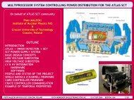
driving frequency. Fig. 2 shows the correspondence between<br />
the driving frequency and the output current at an output<br />
voltage <strong>of</strong> 3500 V<br />
Driving Frequency [kHz]<br />
147.0<br />
146.0<br />
145.0<br />
144.0<br />
143.0<br />
14<br />
17.5<br />
35 70<br />
Output Current [μA]<br />
140<br />
Figure 2: Correspondence between the driving frequency and the<br />
output current at an output voltage <strong>of</strong> 3500 V<br />
The VCO generates the driving frequency and outputs the<br />
driving frequency on a square wave. The square wave called<br />
FQ, which is outputted by the VCO, enables a simple logic<br />
circuit to count pulses. The channel contains a frequency<br />
counter, which sums pulses <strong>of</strong> the square wave in a fixed<br />
time interval. The computer reads the frequency counter<br />
periodically and calculates the driving frequency. The shift <strong>of</strong><br />
the driving frequency thus obtained from the frequency counter
allows calculating the change in the output current.<br />
1) Frequency Counter<br />
The frequency counter is composed <strong>of</strong> a 20-bit counter.<br />
a latch <strong>of</strong> the same bit length and control logic.. The 20-bit<br />
counter is driven by the square wave, summing the pulse for<br />
one second. The latch is updated by the sum <strong>of</strong> the pulses every<br />
one second. The latch holds the latest sum <strong>of</strong> the pulses. The<br />
computer reads the latch asynchronously. So it may happen<br />
that computer reads the latch while the update is in progress.<br />
On such occasions, the control logic reconciles the collision <strong>of</strong><br />
access so that the computer can read either the latest sum or the<br />
sum before the latest update.<br />
F. Block Diagram <strong>of</strong> Channel<br />
A block diagram <strong>of</strong> the channel is shown in Fig 3. Plural<br />
channels will be implemented on the <strong>VME</strong> board. The <strong>VME</strong><br />
board is installed in a crate. The crate powers the <strong>VME</strong> boards<br />
and then the channels. The crate supplies direct-current voltages<br />
for the driver circuit and for the circuitry in the channel.<br />
EN<br />
Driver Circuit<br />
Direct-current<br />
<strong>Power</strong> <strong>Supply</strong><br />
<strong>Voltage</strong>-controlled<br />
Oscillator<br />
FQ<br />
Frequency<br />
Counter<br />
BD<br />
Piezoeramic<br />
Transformer<br />
<strong>Voltage</strong><br />
Comparartor<br />
<strong>Voltage</strong> source<br />
for circuitry<br />
Figure 3: Block diagram <strong>of</strong> the channel<br />
Cockcr<strong>of</strong>t<br />
Walton<br />
Circuit<br />
Error Amplifier<br />
Digital-to-analog<br />
Converter<br />
Load<br />
V. SINGLE CHANNEL <strong>VME</strong> MODULE<br />
The high voltage power supply is tailored to LHC<br />
experiments [1]. A large number <strong>of</strong> high voltage channels need<br />
to be implement in a compact volume for practical usage in<br />
the experiments. A purpose <strong>of</strong> prototyping the single channel<br />
<strong>VME</strong> board is to estimate the volume required for the channel.<br />
The circuit <strong>of</strong> the high voltage power supply in the channel is<br />
essentially identical with the one in [1]. Yet the board is housed<br />
in a <strong>VME</strong> module occupying a single slot as is shown in Fig. 4.<br />
So the circuit is kept low in pr<strong>of</strong>ile. Keeping the pr<strong>of</strong>ile low<br />
restricts components in the circuit, which may produce an<br />
effect on performance. So noises on the output voltage from<br />
the <strong>VME</strong> module are monitored under various conditions .<br />
Driver Switch control<br />
Output terminal<br />
Selection <strong>of</strong> reference voltage source<br />
Refrence voltage input<br />
Auxiliary control input<br />
Figure 4: Picture <strong>of</strong> 4 single channel <strong>VME</strong> module installed in crate<br />
Figure 5: The output voltage from the module is 2000 V at the upper<br />
trace and 3000 V at the lower trace where the output voltage is loaded<br />
by 25 MΩ.
VI. NOISES<br />
A. Noises on Output <strong>Voltage</strong><br />
The output voltage from the <strong>VME</strong> module is observed by<br />
the method described in [1]. The traces <strong>of</strong> the output voltage<br />
are shown in Fig. 5 where the output voltage is loaded with 25<br />
MΩ. In Fig. 5, the output voltage is 2000 V at the upper trace<br />
while 3000 V at the lower trace. The vertical and the horizontal<br />
divisions are 50 mV and 2 µ sec respectively. From the figures<br />
it can be seen that the noises on the output voltage are around<br />
100 mV in peak-to-peak amplitude for a load <strong>of</strong> 25 MΩ.<br />
Good ground and the capacitor with little leak current will<br />
reduce the noises to the level shown in [1]. Yet such the<br />
capacitor may be large in size. So selection <strong>of</strong> the capacitor is<br />
important for high-density packing <strong>of</strong> the channels.<br />
Figure 6: The upper trace shows the output voltage not externally<br />
loaded and the lower trace the output voltage loaded with 25 MΩ at an<br />
output voltage <strong>of</strong> 2000 V.<br />
B. Dependence on Load<br />
Noises on the output voltage may depend on load <strong>of</strong> the<br />
output voltage. Two traces <strong>of</strong> the output voltage shown in<br />
Fig. 6 and 7 gives the dependence. In the figures, the upper<br />
trace shows the output voltage not externally loaded while the<br />
lower trace shows the output voltage loaded with 25 MΩ. The<br />
output voltage is 2000 V in Fig. 6 and 3000 V in Fig. 7. The<br />
vertical and the horizontal divisions are 50 mV and 40 µsec.<br />
The noises at the upper trace is less than two hundred millivolts<br />
in amplitude while the lower trace shows the noises <strong>of</strong><br />
the amplitude around a hundred milli-volts. The output voltage<br />
with heavier load shows smaller noises because the bandwidth<br />
<strong>of</strong> the noises is out <strong>of</strong> a feedback range. So the noises can be<br />
reduced by extending the bandwidth <strong>of</strong> feedback. A circuit for<br />
the bandwidth extension is under test and will be integrated into<br />
the power supply if the test is successful. The circuit is expected<br />
to fairly reduce the noises.<br />
Figure 7: The noise dependence on the load at an output voltage <strong>of</strong><br />
3000 V.<br />
C. Dependence on Parallel Operation<br />
Noises on the output voltage may depend on the number <strong>of</strong><br />
the modules in parallel operation. Fig. 8 shows the traces <strong>of</strong> the<br />
output voltage from the module in parallel operation with other<br />
3 modules, where the output voltage is not externally loaded.<br />
The output voltage is 2000 V at the upper trace and 3000 V at<br />
the lower trace. The vertical and the horizontal divisions are<br />
50 mV and 40 µsec.<br />
The upper traces in Fig. 6 and 7 show the output voltages at
2000 V and at 3000 V respectively from the module in standalone<br />
operation. Comparing these traces with the traces <strong>of</strong> the<br />
parallel operation, it can be seen that the parallel operation does<br />
not increase the noises for these range <strong>of</strong> the output voltage.<br />
Figure 8: The upper and the lower traces show the output voltages<br />
at 2000 V and at 3000 V respectively from the module operating<br />
in parallel with other 3 modules where the output voltage is not<br />
externally loaded.<br />
VII. CONCLUDING REMARKS<br />
There are many things to be considered on designing the<br />
16-channel <strong>VME</strong> board such as the volume for the channel,<br />
selection <strong>of</strong> the capacitor across the output terminals, and the<br />
circuit for the bandwidth extension in addition to lingering<br />
problems which the present prototype leaves untouched; low<br />
efficiency <strong>of</strong> the power supply at the output voltage being low.<br />
The 16-channel <strong>VME</strong> board is now under development, and<br />
will be available in March 2005, when eight 16-channel <strong>VME</strong><br />
modules and 128 channels in total can be used for test. The<br />
16-channel <strong>VME</strong> board occupies 2 slots <strong>of</strong> the <strong>VME</strong> crate,<br />
providing 160 channels <strong>of</strong> the high voltage power supply per<br />
crate. Radiation test by a gamma source and a neutron beam<br />
are now scheduled. A plan for irradiation by a proton beam is<br />
under consideration.<br />
VIII. REFERENCES<br />
[1] Masatosi Imori, Takashi Taniguchi, Toshiyuki Kimura,<br />
and Satoru Imada A Factory <strong>Prototype</strong> <strong>of</strong> <strong>High</strong> <strong>Voltage</strong><br />
<strong>Power</strong> <strong>Supply</strong> Module <strong>Incorporating</strong> Piezoceramic<br />
Transformer In 9th Workshop on Electronics for LHC<br />
Experiments - LECC 2003: Amsterdam, The Netherlands,<br />
29 Sep - 03 Oct 2003 / Ed. by Claude, Sandra - Geneva,<br />
CERN, 2003. [CERN-2003-006; LHCC-G-061; CERN-<br />
LHCC-2003-055] pp.420-424<br />
[2] M. Imori, H. Matsumoto, Y. Shikaze, H. Fuke, T.<br />
Taniguchi, and S. Imada <strong>High</strong> <strong>Voltage</strong> <strong>Power</strong> <strong>Supply</strong><br />
Module Operating in a Magnetic Field Proceedings <strong>of</strong> the<br />
Eighth Workshop on Electronics for LHC Experiments<br />
Colmar, France, 9-13 September 2002.<br />
[3] Yoshiaki Shikaze, Masatosi Imori, Hideyuki Fuke, Hiroshi<br />
Matsumoto, and Takashi Taniguchi, Performance <strong>of</strong> a<br />
<strong>High</strong> <strong>Voltage</strong> <strong>Power</strong> <strong>Supply</strong> <strong>Incorporating</strong> a Ceramic<br />
Transformer, Proceedings <strong>of</strong> the sixth Workshop on<br />
Electronics for LHC Experiments Krakow, Polland, 11-15<br />
September 2000.<br />
[4] Y. Shikaze, M. Imori, H. Fuke, H. Matsumoto, and T.<br />
Taniguchi, A <strong>High</strong>-<strong>Voltage</strong> <strong>Power</strong> <strong>Supply</strong> Operating under<br />
a Magnetic Field, IEEE Transactions on Nuclear Science,<br />
Volume: 48, June 2001 pp. 535 -540.<br />
[5] M. Imori, T. Taniguchi, and H. Matsumoto, Performance<br />
<strong>of</strong> a Photomultiplier <strong>High</strong> <strong>Voltage</strong> <strong>Power</strong> <strong>Supply</strong><br />
<strong>Incorporating</strong> a Piezoelectric Ceramic Transformer, IEEE<br />
Transactions on Nuclear Science, Volume: 47, Dec. 2000<br />
pp. 2045 -2049.<br />
[6] M. Imori, T. Taniguchi, and H. Matsumoto,<br />
A Photomultiplier <strong>High</strong>-<strong>Voltage</strong> <strong>Power</strong> <strong>Supply</strong><br />
<strong>Incorporating</strong> a Ceramic Transformer Driven by<br />
Frequency Modulation, IEEE Transactions on Nuclear<br />
Science, Volume: 45, June 1998 pp. 777 -781.<br />
[7] M. Imori, T. Taniguchi, H. Matsumoto, and T. Sakai, A<br />
Photomultiplier <strong>High</strong> <strong>Voltage</strong> <strong>Power</strong> <strong>Supply</strong> <strong>Incorporating</strong><br />
a Piezoelectric Ceramic Transformer IEEE Transactions<br />
on Nuclear Science, Volume: 43, June 1996 pp.1427 -<br />
1431.<br />
[8] S. Kawasima, O. Ohnishi, H. Hakamata et. al.,<br />
Third Order Longitudinal Mode Piezoelectric Ceramic<br />
Transformer and Its Application to <strong>High</strong>-<strong>Voltage</strong> <strong>Power</strong><br />
Inverter, IEEE Ultrasonic Sympo., Nov., 1994, Cannes,<br />
France. pp.525-530.<br />
[9] O. Onishi, Y. Sasaki, T. Zaitsu, et. al., Piezoelectric<br />
Ceramic Transformer for <strong>Power</strong> <strong>Supply</strong> Operating in<br />
Thickness Extensional Vibration Mode, IEICE Trans.<br />
Fundamentals. Vol. E77-A, No. 12 December 1994. pp.<br />
2098-2105.<br />
[10] T. Zaitsu, T. Inoue, O. Onishi and A. Iwatani, 2 M<br />
Hz <strong>Power</strong> Converter with Piezoelectric Transformer,<br />
INTELEC’92 Proc., pp.430-437, Oct. 1992.<br />
[11] C. Y. Lin and F. C. Lee, Design <strong>of</strong> Piezoelectric<br />
Transformer Converters Using Single-ended Topologies,<br />
1994 VPEC Seminar Proceedings, pp.107-112.