MODEL FH OIL BURNERS - Puerto Rico Suppliers .com
MODEL FH OIL BURNERS - Puerto Rico Suppliers .com
MODEL FH OIL BURNERS - Puerto Rico Suppliers .com

Create successful ePaper yourself
Turn your PDF publications into a flip-book with our unique Google optimized e-Paper software.
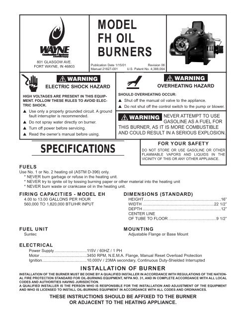
801 GLASGOW AVE.<br />
FORT WAYNE, IN 46803<br />
ELECTRIC SHOCK HAZARD<br />
HIGH VOLTAGES ARE PRESENT IN THIS EQUIP-<br />
MENT. FOLLOW THESE RULES TO AVOID ELEC-<br />
TRIC SHOCK.<br />
▲ Use only a properly grounded circuit. A ground<br />
fault interrupter is re<strong>com</strong>mended.<br />
▲ Do not spray water directly on burner.<br />
▲ Turn off power before servicing.<br />
▲ Read the owner’s manual before using.<br />
SPECIFICATIONS<br />
<strong>MODEL</strong><br />
<strong>FH</strong> <strong>OIL</strong><br />
<strong>BURNERS</strong><br />
Publication Date 1/15/01 Revision 06<br />
Manual 21827-001 U.S. Patent No. 4,388,064<br />
OVERHEATING HAZARD<br />
SHOULD OVERHEATING OCCUR:<br />
▲ Shut off the manual oil valve to the appliance.<br />
▲ Do not shut off the control switch to the pump or blower.<br />
NEVER ATTEMPT TO USE<br />
GASOLINE AS A FUEL FOR<br />
THIS BURNER, AS IT IS MORE COMBUSTIBLE<br />
AND COULD RESULT IN A SERIOUS EXPLOSION.<br />
FUELS<br />
Use No. 1 or No. 2 heating oil (ASTM D-396) only.<br />
* NEVER burn garbage or refuse in the heating unit.<br />
* NEVER try to ignite oil by tossing burning paper or other material into the heating unit<br />
* NEVER burn waste or crankcase oil in the heating unit.<br />
FIRING CAPACITIES - <strong>MODEL</strong> EH<br />
4.00 to 13.00 GALLONS PER HOUR<br />
560,000 TO 1,820,000 BTU/HR INPUT<br />
FUEL UNIT<br />
Suntec<br />
FOR YOUR SAFETY<br />
DO NOT STORE OR USE GASOLINE OR OTHER<br />
FLAMMABLE VAPORS AND LIQUIDS IN THE<br />
VICINITY OF THIS OR ANY OTHER APPLIANCE.<br />
DIMENSIONS (STANDARD)<br />
HEIGHT.....................................................................16”<br />
WIDTH ................................................................22 1/2”<br />
DEPTH ......................................................................12”<br />
CENTER LINE<br />
OF TUBE TO FLOOR ...........................................9 1/2”<br />
MOUNTING<br />
Adjustable Flange or Base Mount<br />
ELECTRICAL<br />
Power Supply .............................115V / 60HZ / 1 PH<br />
Motor ..........................................3450 RPM, N.E.M.A. Flange, Manual Reset Overload Protection<br />
Ignition........................................10,000V / 23MA secondary, Continuous Duty-Shielded Interrupted<br />
INSTALLATION OF BURNER<br />
INSTALLATION OF THE BURNER MUST BE DONE BY A QUALIFIED INSTALLER IN ACCORDANCE WITH REGULATIONS OF THE NATION-<br />
AL FIRE PROTECTION STANDARD FOR <strong>OIL</strong>-BURNING EQUIPMENT, NFPA NO. 31, AND IN COMPLETE ACCORDANCE WITH ALL LOCAL<br />
CODES AND AUTHORITIES HAVING JURISDICTION.<br />
A QUALIFIED INSTALLER IS THE PERSON WHO IS RESPONSIBLE FOR THE INSTALLATION AND ADJUSTMENT OF THE EQUIPMENT<br />
AND WHO IS LICENSED TO INSTALL <strong>OIL</strong>-BURNING EQUIPMENT IN ACCORDANCE WITH ALL CODES AND ORDINANCES.<br />
THESE INSTRUCTIONS SHOULD BE AFFIXED TO THE BURNER<br />
OR ADJACENT TO THE HEATING APPLIANCE.
TO THE HOMEOWNER<br />
Since 1928, Wayne has supplied the Homeowners of the world with oil burners. You are obtaining a quality burner<br />
unsurpassed in engineering design and product development. It will provide you with many years of efficient, troublefree<br />
operation, if properly installed and serviced. Please read this manual carefully.<br />
Wayne warrants its burners specifically to those who have purchased it for resale, including your dealer. If, in any<br />
case, you have a problem with your burner, or its installation, you should contact your dealer for assistance.<br />
APPROVALS<br />
This burner <strong>com</strong>plies with ANSI/UL Standard 296 and is for use with No. 1 or No. 2 fuel oil and is U/L listed for use<br />
with Group I or Group II primary safety controls. State and local approvals are shown on burner rating label. All burners<br />
should be installed in accordance with the National Fire Protection Association, and in <strong>com</strong>plete accordance with<br />
al local codes and authorities having jurisdiction. Regulation of these authorities take precedent over the general<br />
instructions provided in this manual.<br />
GENERAL INFORMATION<br />
When installing the appliance and/or burner be sure to provide adequate space for easy service and maintenance.<br />
Prior to installation of the oil burner, the heating system should be carefully inspected for defects and cleanliness. The<br />
flue passages and heat absorbing surfaces must be clean to assure maximum heat transfer, soot acts as an insulator<br />
retarding the transfer of heat. The <strong>com</strong>bustion chamber, flue gas passages, and all doors and openings must be<br />
sealed tight to eliminate air infiltration. Excess air, decreases CO2 levels and thus lowers efficiency. Inspect the flue<br />
and chimney for leaks and obstructions, be sure the chimney is of adequate size and height. Install a draft regulator<br />
the same size as the flue pipe (see paragraph under Draft Regulators).<br />
COMBUSTION CHAMBER<br />
The purpose of a <strong>com</strong>bustion chamber is to maintain a high flame temperature, by reflecting the heat back into the<br />
flame. A high temperature assures greater <strong>com</strong>bustion efficiency and lower stack losses. An insulating refractory or a<br />
Fiber Fax type chamber can be used with this burner. It is important to select and install, if necessary, the correct size<br />
chamber on a conversion job. On the Flamelock conversion burners the atomized oil burns just off the Flamelock. On<br />
all oil burners the atomized oil must not touch the sides or bottom of chamber, or smoke will result. To eliminate the<br />
smoke, excess air will be required, resulting in high stack temperature and lower <strong>com</strong>bustion efficiency. Install burner<br />
so the face of air cone of burner is set 1/4” behind the inside front wall of the chamber (See Figure 3, page 6).<br />
Caution on installing Flamelock burners in stainless steel chambers should be taken, because of the higher temperature<br />
levels produced by high performance flame retention burners. The temperature may exceed the temperature<br />
ratings of the stainless steel chamber and can result in chamber burn outs. When you are replacing a standard burner<br />
with a flame retention burner, take the following precautions: (1) use pliable Ceramic Liner to line the inside of<br />
chamber, (2) adjust burner (See column under “Final Adjustments”).<br />
FUEL PUMPS AND <strong>OIL</strong> LINES<br />
The Model <strong>FH</strong> oil burner is provided with a two stage 3450 RPM fuel pumps with the by-pass plug removed for a single<br />
pipe installation. This is satisfactory where the fuel supply is on the same level, or above burner, permitting gravity<br />
flow of oil. Never exceed 3 PSI pressure to the suction side of fuel pump. A pressure over 3 PSI may cause damage<br />
to the shaft seal and allow it to leak oil. When it is necessary to lift the oil to the burner, a return line should be<br />
run between fuel pump and oil supply. (If lift exceeds 10 feet, a two stage fuel pump must be used with a return line.)<br />
When a two line installation is made, the by-pass plug must be installed. This is supplied with the burner attached to<br />
fuel pump, along with an information pump data sheet in a plastic bag. When oil lines are continuous runs of heavy<br />
wall copper tubing is re<strong>com</strong>mended. Be sure that all connections are absolutely air-tight. Check all connections and<br />
joints. Flared fittings are re<strong>com</strong>mended. Do not use <strong>com</strong>pression fittings. Avoid running tubing against the appliance<br />
and across ceiling or floor joist; if possible install under floor. Avoid using fittings in inaccessible locations. If possible,<br />
avoid running oil lines overhead. Specific information on piping, connections, lift capabilities and tank installations is<br />
provided in the instruction sheet of the fuel pump manufacturer. Use an oil filter of adequate size for all installations.<br />
Install inside the building between the tank shutoff valve and the burner. Install shutoff valve in oil supply line in accessible<br />
locations, one close to the tank, another close to the oil burner but ahead of the filter. NOTE: If the maximum<br />
burner firing rate exceeds the integral fuel pump strainer rating, an external U/L listed filter/strainer must be placed in<br />
the fuel line between the fuel tank and burner fuel pump.<br />
TANKS AND PIPING<br />
Local codes and regulations must be followed regarding tank and burner installation. Check existing tanks for water<br />
and sludge accumulation, clean if necessary. Also clean or replace existing piping.<br />
WIRING<br />
All wiring must <strong>com</strong>ply with the National Electric Code and local ordinances. Refer to diagram supplied with burner or<br />
controls, making sure the burner and controls are wired correctly and that the line switch is properly connected to a<br />
20 amp fused service.<br />
2
AIR SUPPLY FOR COMBUSTION<br />
A burner shall not be installed in an area where facilities for normal air circulation or infiltration are so limited as to interfere<br />
with ready obtainment of all air necessary for proper <strong>com</strong>bustion and venting. When the heating appliance is<br />
installed in a confined space, two permanent openings shall be provided. One near the top of the enclosure and one<br />
near the bottom. Each opening shall have a free area of not less than one square inch per 1000 BTU per hour (140<br />
square inch per gph) of the total input rating of all the appliances in the enclosure. When the house is out of unusually<br />
tight construction, has a kitchen ventilating system, exhaust fans, clothes dryer or vented fireplaces, it is re<strong>com</strong>mended<br />
that <strong>com</strong>bustion air be supplied through two permanent openings. The openings shall <strong>com</strong>municate directly,<br />
or by means of ducts, with outdoors or to such spaces (attic or crawl) that freely <strong>com</strong>municate with outdoors. For additional<br />
information, refer to ANSI standard NFPA 31.<br />
CHIMNEY<br />
Follow the re<strong>com</strong>mendations of the appliance manufacturer. A chimney shall be capable of producing a draft as<br />
required by the appliance and as re<strong>com</strong>mended by the appliance manufacturer. It must be properly designed, of adequate<br />
size, and should be above the surrounding objects, tile-lined, with no obstructions, and be in good state of repair.<br />
The smoke pipe should set flush with the inside of tile and be cemented in place. All cleanout doors should be sealed.<br />
A draft inducer may be used to over<strong>com</strong>e inadequate draft conditions. If a draft inducer is used, provisions must be<br />
made to insure the burner does not operate if the draft inducer fails.<br />
DRAFT REGULATORS<br />
A draft regulator shall be provided unless otherwise specified by the appliance manufacturer. The draft regulator shall<br />
be installed in accordance with local codes and regulations or in the absence of local codes, with the American National<br />
Standard NFPA31. Refer to appliance manufacturer’s instructions for re<strong>com</strong>mended overfire and stack draft.<br />
NOZZLE AND AIR CONE SELECTION<br />
The <strong>FH</strong> oil burner typically fires well with a solid or semi-solid nozzle with a spray angle of 80, 70 or 60 degrees. In<br />
most upgrading or conversion installations, the use of an 80 degree solid nozzle is the best way to start with. Always<br />
use the proper nozzle size, spray cone type and spray angle the appliance manufacturer re<strong>com</strong>mends. Should this<br />
information not be available, your own good judgement will prevail. Under no circumstances attempt to fire the <strong>FH</strong> oil<br />
burner under its 4.00 gph minimum or over its 13.00 gph maximum input ratings.<br />
<strong>FH</strong> oil burners are built with a 4.00 to 11.00 GPH H-1 rating as standard. To convert to the 11.00 to 13.00 GPH<br />
H-2 rating:<br />
1. Change the 4-3/16” I.D. cast iron cone (P/N 13127) installed to the 4-3/8” I.D. cast iron air cone (P/N 13128)<br />
supplied.<br />
2. To change air cones, remove the phillips head counter sunk 8-32 screw securing the existing air cone in the<br />
air tube end, remove the air cone.<br />
3. Install the larger air cone.<br />
Once the proper cast air cone has been installed the nozzles can be installed from the air tube end into the<br />
Flamelock/nozzle adaptor. Thread each nozzle into the adaptor finger tight then tighten securely with a nozzle<br />
wrench. CAUTION: DO NOT OVER TIGHTEN. At this time position the Flamelock flush with the cast iron air cone<br />
face. To position the Flamelock gun assembly forward, loosen the gun assembly 3/8-24 hex lock nut and 5/16”<br />
hex slotted slot cover screw. Once in the the required position, retighten the hex lock nut and slot cover screw.<br />
To remove the Flamelock gun assembly once the burner has been installed on the appliance, remove the copper oil line<br />
where it attaches with the gun assembly oil line adaptor fitting and remove the 9/16” hex gun assembly locknut. Next,<br />
remove the ignition transformer hold down the clip and swing open the ignition transformer to the left. Now grasp the rear<br />
of the gun assembly where the oil line fitting adaptor exits thru the housing and pull the oil line adaptor to the right out of<br />
the housing slot and slot cover. Gently lift, do not force, the rear of the gun assembly, rotating the oil line fitting adaptor<br />
up at 45 degrees pulling the entire gun assembly out of the housing opening.<br />
Remove and install nozzles finger tight in the regular or Flamelock nozzle adaptor, then securely tighten nozzles with<br />
a nozzle wrench. Check electrodes for proper position (see Figure 1, page 6). Reinstall the Flamelock gun assembly into<br />
the burner by repeating the above steps for removal in reverse order. Once reinstalled, securely tighten the 3/8-24 hex<br />
gun assembly lock nut and the 7/16” hex oil line flare nut to the oil line fitting adaptor.<br />
CAUTION: Close the ignition transformer and assure there is positive spring contact with<br />
the brass buss bars. Take care not to pinch the ignition transformer lead wires between the housing and cover plate.<br />
Reinstall the ignition transformer hold down clip and tighten the clip screw securely.<br />
3
4<br />
Care should be taken when closing the transformer not to pinch the lead wires between the<br />
housing and cover plate.<br />
STARTING PROCEDURE<br />
STARTING BURNER<br />
Be sure main switch is in “OFF” position, thermostat is substantially above room temperature, the oil tank is filled, all<br />
valves are open, and controls set for operation. Adjust air supply on burner by loosening screw on interlocking air<br />
bands, and open partially. Open the inspection door and turn on switch. Prime pump according to the pump manufacturer’s<br />
re<strong>com</strong>mendations and check pressure. If safety lockout occurs, reset after one or two minutes. Do not run fuel<br />
unit dry for more than five minutes or damage to the pump may result. When flame is established make a temporary<br />
air adjustment for a clean <strong>com</strong>bustion flame, reduce air supply until flame tips appear slightly smoky, then readjust so<br />
flame tips are clean looking. Leave inspection door open until chamber is dry. When normal temperature are reached,<br />
close inspection door. (See paragraph under “Draft Regulators”).<br />
FINAL ADJUSTMENTS<br />
At this point a final adjustment should be made by the use of a COMBUSTION TEST KIT. After operating ten minutes<br />
to warm up unit, a smoke tester should be used to take a smoke reading. Smoke test should read no greater than #1<br />
(Shell Bacarach scale), and less than a #1 smoke is desired. At times, a new heating unit requires more time than this<br />
to burn clean due to the oil film on the new heater unit surfaces. Recheck draft and take a CO2 reading over the fire<br />
and in the stack. If a large differential between CO2 readings is noted, air leakage is the most <strong>com</strong>mon cause. CO2 readings<br />
must be taken ahead of draft control, if used.The CO2 measured in the stack should be at least 10% for oil rates<br />
over 1.00GPH. Units should be started and stopped several times to assure good operation. Open inspection door, turn<br />
off valve, and check out safety timing of <strong>com</strong>bustion control. Check operation of limit controls and thermostat. Check<br />
for oil leaks. NOTE: ALL NEW INSTALLATIONS SHOULD BE REINSPECTED AFTER ONE OR TWO WEEKS OF<br />
NORMAL OPERATION.<br />
SETTING COMBUSTION EFFICIENCY<br />
(A) Selecting firing rate desired. (B) Install proper nozzles for appliance (see paragraph under “Nozzle and Air Cone<br />
Selection”). (C) Fire burner, adjust interlocking air bands for yellow tips above <strong>com</strong>bustion chamber. (D) Record CO2<br />
and smoke. If CO2 is low, adjust gun setting back 1/32” and repeat CO2 and smoke test. Continue this adjustment until<br />
desired CO2 and smoke is obtained. Record stack temperature. (E) Check lighting with cold and hot chamber. (F) Lock<br />
all adjustment screws.<br />
FINAL CHECKS<br />
Be sure all screws are locked, and the controls on heating unit are adjusted in accordance with the heater and control<br />
manufacturer’s instruction sheets.<br />
MAINTENANCE<br />
<strong>OIL</strong>ING MOTOR – Proper lubrication of the motor will prolong its service life. Oil sleeve bearing motors with 6 drops of<br />
SAE 20 oil once a year. DO NOT OVER <strong>OIL</strong>. Ball-bearing motors do not require oiling under normal service conditions.<br />
The bearing type is printed on the motor nameplate.<br />
FILTER – The oil filter cartridge should be replaced once a year so the fuel oil will not be<strong>com</strong>e contaminated and plug<br />
up fuel pump and nozzle of oil burner.<br />
NOZZLES – The nozzles should be changed at least once a year before the start-up of the heating season. Replace<br />
with proper nozzles.<br />
COMPONENTS – If for any reason any of the burner parts have to be replaced, always use parts re<strong>com</strong>mended by<br />
the manufacturer. Specify part numbers and description when ordering. (IN ALL COMMUNICATIONS STATE BURN-<br />
ER <strong>MODEL</strong>, SPECIFICATION NUMBER, SERIAL NUMBERS AND APPLIANCE MANUFACTURERS AND APPLI-<br />
ANCE <strong>MODEL</strong> DESIGNATION).<br />
ELECTRODE SETTINGS – This is very important for reliable ignition of the oil; check these once a year in accordance<br />
with the instructions provided in this manual. Replace electrodes if worn excessively or if porcelain insulator is oil<br />
soaked or cracked.<br />
FAN & BLOWER HOUSING – This must be kept clean, free of dirt and lint; open transformer to check fan blades from<br />
above. CAUTION: Be sure the electric power is off on burner when the transformer is opened up for this inspection.
15<br />
14<br />
13<br />
12<br />
11<br />
10<br />
9<br />
8<br />
7<br />
6<br />
5<br />
4<br />
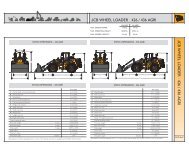
EFFICIENCY CHART FOR NO. 2 FUEL <strong>OIL</strong><br />
NET STACK TEMPERATURE (DEGREES F˚)<br />
300˚ 350˚ 400˚ 450˚ 500˚ 550˚ 600˚ 650˚ 700˚ 750˚ 800˚ 850˚ 900˚<br />
871 ⁄ 2 861 ⁄ 2 851 ⁄ 4 841 ⁄ 4 831 ⁄ 4 82 81 793 ⁄ 4 783 ⁄ 4 771 ⁄ 2 761 ⁄ 2 751 ⁄ 2 741 ⁄ 4<br />
871 ⁄ 2 861 ⁄ 4 85 84 83 813 ⁄ 4 803 ⁄ 4 791 ⁄ 4 781 ⁄ 2 771 ⁄ 4 76 75 733 ⁄ 4<br />
871 ⁄ 4 86 843 ⁄ 4 823 ⁄ 4 823 ⁄ 4 811 ⁄ 2 801 ⁄ 4 79 78 763 ⁄ 4 751 ⁄ 2 741 ⁄ 2 73<br />
87 853 ⁄ 4 841 ⁄ 2 831 ⁄ 2 821 ⁄ 2 811 ⁄ 4 80 783 ⁄ 4 771 ⁄ 2 761 ⁄ 4 751 ⁄ 4 74 721 ⁄ 4<br />
863 ⁄ 4 851 ⁄ 2 841 ⁄ 4 831 ⁄ 4 82 803 ⁄ 4 791 ⁄ 2 781 ⁄ 4 77 753 ⁄ 4 741 ⁄ 2 731 ⁄ 2 713 ⁄ 4<br />
861 ⁄ 2 851 ⁄ 4 84 831 ⁄ 4 811 ⁄ 2 801 ⁄ 4 79 773 ⁄ 4 761 ⁄ 2 751 ⁄ 4 733 ⁄ 4 723 ⁄ 4 71<br />
861 ⁄ 4 85 833 ⁄ 4 821 ⁄ 2 811 ⁄ 4 793 ⁄ 4 781 ⁄ 2 771 ⁄ 4 753 ⁄ 4 741 ⁄ 2 73 711 ⁄ 2 701 ⁄ 4<br />
86 843 ⁄ 4 831 ⁄ 2 82 803 ⁄ 4 791 ⁄ 4 78 761 ⁄ 2 751 ⁄ 4 733 ⁄ 4 721 ⁄ 4 703 ⁄ 4 691 ⁄ 2<br />
853 ⁄ 4 841 ⁄ 2 83 811 ⁄ 2 801 ⁄ 4 783 ⁄ 4 771 ⁄ 4 753 ⁄ 4 741 ⁄ 2 73 711 ⁄ 2 70 681 ⁄ 2<br />
851 ⁄ 2 84 821 ⁄ 2 81 791 ⁄ 2 78 761 ⁄ 2 75 733 ⁄ 4 72 701 ⁄ 2 69 671 ⁄ 2<br />
85 831 ⁄ 2 82 801 ⁄ 2 783 ⁄ 4 771 ⁄ 4 753 ⁄ 4 741 ⁄ 4 723 ⁄ 4 71 691 ⁄ 2 68 661 ⁄ 4<br />
841 ⁄ 2 83 811 ⁄ 2 793 ⁄ 4 78 761 ⁄ 2 75 731 ⁄ 4 713 ⁄ 4 70 681 ⁄ 4 663 ⁄ 4 65<br />
84 821 ⁄ 4 803 ⁄ 4 79 771 ⁄ 4 753 ⁄ 4 74 721 ⁄ 4 703 ⁄ 4 683 ⁄ 4 67 651 ⁄ 4 631 ⁄ 2<br />
831 ⁄ 2 813 ⁄ 4 80 781 ⁄ 4 761 ⁄ 2 743 ⁄ 4 73 711 ⁄ 4 691 ⁄ 2 671 ⁄ 2 651 ⁄ 2 633 ⁄ 4 62<br />
83 81 791 ⁄ 4 771 ⁄ 2 751 ⁄ 2 733 ⁄ 4 713 ⁄ 4 70 68 66 64 62 60<br />
821 ⁄ 4 801 ⁄ 4 781 ⁄ 2 761 ⁄ 2 741 ⁄ 2 721 ⁄ 2 701 ⁄ 2 681 ⁄ 2 661 ⁄ 2 641 ⁄ 4 621 ⁄ 4 60 58<br />
811 ⁄ 2 791 ⁄ 2 771 ⁄ 4 751 ⁄ 4 731 ⁄ 4 71 69 67 643 ⁄ 4 621 ⁄ 2 601 ⁄ 4 573 ⁄ 4 551 ⁄ 2<br />
803 ⁄ 4 781 ⁄ 2 761 ⁄ 4 74 713 ⁄ 4 691 ⁄ 2 671 ⁄ 4 65 623 ⁄ 4 601 ⁄ 4 573 ⁄ 4 551 ⁄ 2 53<br />
793 ⁄ 4 771 ⁄ 4 75 721 ⁄ 2 70 673 ⁄ 4 651 ⁄ 4 623 ⁄ 4 601 ⁄ 4 571 ⁄ 2 551 ⁄ 2 521 ⁄ 2 50<br />
781 ⁄ 2 76 731 ⁄ 2 71 68 651 ⁄ 2 63 601 ⁄ 4 571 ⁄ 2 541 ⁄ 2 513 ⁄ 4 49 461 ⁄ 2<br />
771 ⁄ 4 741 ⁄ 2 713 ⁄ 4 69 653 ⁄ 4 63 60 57 54 51 48 451 ⁄ 2 421 ⁄ 2<br />
751 ⁄ 2 721 ⁄ 2 69 661 ⁄ 4 63 60 563 ⁄ 4 531 ⁄ 2 501 ⁄ 4 47 431 ⁄ 2 401 ⁄ 4 363 ⁄ 4<br />
731 ⁄ 4 693 ⁄ 4 661 ⁄ 4 623 ⁄ 4 591 ⁄ 4 553 ⁄ 4 52 481 ⁄ 2 45 411 ⁄ 4 371 ⁄ 2 333 ⁄ 4 30<br />
5
6<br />
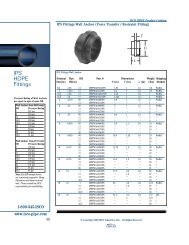
INTERMITTENT IGNITION<br />
FIGURE 2<br />
TO DETERMINE THE AIR TUBE LENGTH<br />
The Air Tube Length (Dim. A) is the distance from the front<br />
of Air Tube Retainer Flange to the face of Air Cone. Note<br />
adjustable flange width.<br />
FIGURE 3<br />
FIGURE 1<br />
FIGURE 4<br />
FIGURE 5
STANDARD <strong>MODEL</strong> <strong>FH</strong> <strong>OIL</strong> BURNER PARTS LIST<br />
DESCRIPTION PART NO.<br />
MOTOR, 1/2HP - 120V/60HZ, 3450RPM 21819-002<br />
MOTOR MOUNTING SCREWS 12701<br />
FAN 21702-002<br />
COUPLING 13142-002<br />
PUMP-SUNTEC B2TB8261 101201-001<br />
PUMP MOUNTING SCREWS 12701<br />
VALVE-HONEYWELL V4046A1009 14409-002<br />
VALVE MOUNTING NIPPLE 13384<br />
VALVE MOUNTING NIPPLE LOCKNUT 12910<br />
PUMP AND VALVE ELBOW 12091<br />
<strong>OIL</strong> LINE ASSEMBLY-9 3/4” 13531<br />
<strong>OIL</strong> LINE ASSEMBLY-6 1/4” 13154<br />
TRANSFORMER KIT 23101-<strong>FH</strong><br />
TRANSFORMER HINGE CLIP 12351<br />
TRANSFORMER HINGE CLIP SCREW 13036<br />
TRANSFORMER COVER SCREW 16156<br />
TRANSFORMER SUPPORT 12641<br />
TRANSFORMER SUPPORT NUT 15872<br />
CONTROL-HONEYWELL R8184G1294 13077<br />
CAD CELL-HONEYWELL C554A1216 13666<br />
HOUSING ASSEMBLY (INCL J-BOX) 31141-012<br />
J-BOX ONLY 20369<br />
J-BOX CHASE NIPPLE 12909<br />
J-BOX LOCKNUT 12901<br />
J-BOX ATTACHMENT SCREW 16156<br />
WIRE CLIPS 12651<br />
WIRE CLIP SCREWS 16156<br />
WIRE CLIP NUTS 100601-001<br />
<strong>OIL</strong> LINE SLOT COVER 14995<br />
<strong>OIL</strong> LINE SLOT COVER SCREW 12697<br />
DESCRIPTION PART NO.<br />
<strong>OIL</strong> LINE LOCKNUT 12342<br />
AIR BAND-INNER 2669-002<br />
AIR BAND-OUTER 2668-002<br />
AIR BAND SCREW 12702<br />
AIR TUBE/FLANGE-STD 10” BURNER 31143-012<br />
AIR TUBE/FLANGE-STD 15” BURNER 31145-012<br />
AIR CONE-4 3/8” ID (4.00-11.00GPH) 13127<br />
AIR CONE- 4 13/16” ID (OVER 11 GPH) 13128<br />
AIR CONE MOUNTING SCREW 12699<br />
GUN ASSEMBLY-STD 10” UNIT 30728-002<br />
GUN ASSEMBLY-STD 15” UNIT 30728-008<br />
NOZZLES (AS SPECIFIED/REQUIRED) VARIES<br />
DUAL NOZZLE ADAPTER 12573<br />
FLAMELOCK ASSEMBLY 13129<br />
TRIPOD ELECTRODE SUPPORT 12596<br />
ELECTRODE SUPPORT BRUSHINGS 12408<br />
ELECTRODE SUPPORT SET SCREWS 12693<br />
ELECTRODE LOCKING SCREWS 12694<br />
DISC-2 1/2” SOLID 13409<br />
DISC MOUNTING SCREW 100603-028<br />
CAD CELL MOUNTING BRACKET 13078<br />
ELECTRODE STEM-RIGHT HAND 13149<br />
ELECTRODE STEM-LEFT HAND 13150<br />
ELECTRODE INSULATOR 100005-002<br />
ELECTRODE ASSEMBLY NUTS 13110<br />
BUSS BAR 100004-036<br />
BUSS BAR SUPPORT 13276-002<br />
ADJUSTABLE FLANGE ASSEMBLY 20471<br />
FLANGE GASKET 20529<br />
BASE ASSEMBLY 20095<br />
7
8<br />
WAYNE COMBUSTION SYSTEMS<br />
801 GLASGOW AVE.<br />
FORT WAYNE, IN 48803<br />
LIMITED WARRANTIES FOR <strong>OIL</strong> AND<br />
GAS <strong>BURNERS</strong>, MADE BY WAYNE AND<br />
USED IN RESIDENTIAL INSTALLATIONS<br />
WAYNE COMBUSTION SYSTEMS (“WAYNE”) warrants to those who purchase its Oil Burner Models for resale or<br />
for incorporation into a product of resale, that its burner is free from defects in material and workmanship under normal<br />
use and service for thirty-six (36) months from the date of manufacture. ALL GAS <strong>BURNERS</strong> manufactured by<br />
“WAYNE” will be similarly warranted for eighteen(18) months from date of manufacture except where original manufacture<br />
offers a greater warranty. (Reference #6 below) THESE LIMITED WARRANTIES DO NOT APPLY UNLESS<br />
THE BURNER COVERED BY IT IS PROPERLY INSTALLED BY A QUALIFIED, COMPETENT TECHNICIAN, WHO<br />
IS LICENSED WHERE STATE AND/OR LOCAL CODES PREVAIL, AND WHO IS EXPERIENCED IN MAKING SUCH<br />
INSTALLATIONS, IN ACCORDANCE WITH NFPA #31 OF THE NATIONAL FIRE PROTECTION ASSOCIATION AND<br />
IN ACCORDANCE WITH ALL LOCAL, STATE AND NATIONAL CODES.<br />
Any IN-WARRANTY burner <strong>com</strong>ponent which is defective in material or workmanship will be either repaired or<br />
replaced as follows:<br />
1. Fuel units, motors, transformers, gas valves, and controls should be returned to an authorized service station or<br />
distributor of WAYNE for determination of applicability of this LIMITED WARRANTY as to either repair or<br />
replacement, where said service station or distributor is reasonably available in the customer’s locality. The<br />
manufacturers of burner <strong>com</strong>ponents regularly publish and distribute listings showing the locations of their network<br />
of service stations. Where such local service is NOT available for the burner <strong>com</strong>ponents described above or other<br />
burner parts are involved, these items should be returned, freight prepaid, to WAYNE Service Department, 801<br />
Glasgow Ave, Fort Wayne, Indiana 46803.<br />
2. Burners and/or <strong>com</strong>ponent(s) determined to be covered under this LIMITED WARRANTY by WAYNE shall be<br />
repaired or replaced at WAYNE’s sole option.<br />
3. WAYNE is not responsible for any labor cost for the removal and replacement of said burner or burner <strong>com</strong>ponents<br />
and equipment associated therewith.<br />
4. A burner so repaired will then carry the LIMITED WARRANTY equal to the unexpired portion of the original<br />
burner LIMITED WARRANTY.<br />
5. If inspection by WAYNE does NOT disclose any defect covered by this LIMITED WARRANTY, the burner or<br />
burner <strong>com</strong>ponent(s) will be either repaired or replaced at the expense of the customer and WAYNE’s regular<br />
charges will apply.<br />
6. If the original manufacturer of a burner <strong>com</strong>ponent offers a warranty greater than either of our LIMITED<br />
WARRANTIES described above, then this portion will be added to our LIMITED WARRANTY.<br />
This LIMITED WARRANTY does NOT cover products which have been damaged as the result of accident, abuse, misuse,<br />
neglect, improper installations, improper maintenance or failure to operate in accordance with WAYNE’s written<br />
instructions.<br />
These LIMITED WARRANTIES do not extend to anyone except the first purchaser at retail and only when the burner<br />
is in the original installation site.<br />
IMPLIED WARRANTIES OF MERCHANTABILITY AND FITNESS FOR A PARTICULAR PURPOSE SHALL BE LIM-<br />
ITED TO THE DURATION OF THE LIMITED EXPRESS WARRANTIES CONTAINED HEREIN. WAYNE EXPRESS-<br />
LY DISCLAIMS AND EXCLUDES ANY LIABILITY FOR CONSEQUENTIAL OR INCIDENTAL DAMAGES OF ANY<br />
NATURE FOR BREACH OF ANY EXPRESS OR IMPLIED WARRANTY.<br />
Some states do not allow limitation on how long an implied warranty lasts, so the above limitation may not apply to you.<br />
Also, some states do not allow the exclusion or limitation of incidental or consequential damages, so the above limitation<br />
or exclusion may not apply to you. WAYNE neither assumes or authorizes any person to assume for WAYNE any<br />
other liability or obligation in connection with the sale of these products. This warranty gives you specific legal rights,<br />
and you may also have other rights which vary from state to state.
Notes<br />
9
10<br />
Notes
<strong>OIL</strong> BURNER CERTIFICATE<br />
AS REQUIRED BY COMMERCIAL STANDARD CS75-56<br />
The _____________________________________ Oil Burner Model No. _____________, Serial No. ______________. installed at ________________________<br />
(Make) (Address of Installation)<br />
bears a label evidencing <strong>com</strong>pliance with <strong>com</strong>mercial Standard CS75-56, and has been installed in accordance with the instructions in the manufacturer’s<br />
installation manual and in conformity with local regulations, codes, and ordinances.<br />
The boiler ( ), furnace ( ), is a __________________________________ No. ____________, and the heating load consists of:<br />
1. ______ Btu, or ____ square feet steam ( ), hot water ( ), radiation; and<br />
2. ______ Btu, or ____ square feet of equivalent steam ( ), hot water ( ), radiation in domestic hot water load; or<br />
3. ______ Btu, or ____ square inches of cross-sectional area of warm air supply pipes measured at the furnace take off; or<br />
4. ______ Btu, or ____ square feet of equivalent steam ( ), hot water ( ), radiation in the following special load:<br />
_________________________________________________________________________________________________________________________________<br />
All necessary permits have been secured, and the installation has been tested in accordance with the test procedure of Commercial Standard CS75-56 and the<br />
following reading taken:<br />
{<br />
{<br />
Over Fire ___________________<br />
CO<br />
At Breaching ________________<br />
Stack Temperatures at breeching_______________________˚F<br />
Over Fire ___________________<br />
Draft<br />
Firing Rating__________________________________Gals/hr.<br />
At Breaching ________________<br />
All controls and limiting devices have been checked for proper operation ___________<br />
Fuel used, Grade No. ______ of Commercial Standard CS12-48. Field service equipment smoke scale reading ________<br />
The above test results are certified to be true: ____________________________________________________________________________________________<br />
(Name of Company making installation)<br />
For Service Call:<br />
___________________________________________________________ Per _____________________________________________________________<br />
(Name) (Signature)<br />
___________________________________________________________ ________________________________________________________________<br />
(Address) (Address)<br />
___________________________________________________________ ________________________________________________________________<br />
(Telephone)<br />
Date _______________________________________________________<br />
(Telephone)<br />
DIRECTIONS FOR THE OPERATION AND CARE OF<br />
<strong>OIL</strong> BURNER<br />
Read Instructions Carefully and Hang This Card Near Burner for Future Reference<br />
(A) TO START BURNER:<br />
1. Check for oil in the storage tank.<br />
2. Fuses in the main switch must be good.<br />
3. Have oil burner switch open.<br />
4. Set room thermostat about 10 degrees higher than room temperature to make sure the<br />
thermostat contacts are made. Limit control must be set high enough to make contact also.<br />
5. Oil valve at the tank should be open and the check valve in return line properly installed so<br />
oil can return to tank.<br />
6. Be sure nozzle of proper size for heater is in the adapter and tightly screwed down, and<br />
that the electrodes are properly spaced (See Manual). With heating plant door open, close<br />
the burner switch; and if wiring is properly done and all controls properly installed and<br />
adjusted, the burner should start. If not, check primary relay first to be sure it is properly<br />
set; and if burner does not start, recheck wiring and all controls thoroughly.<br />
7. If burner is installed with a single oil line, the fuel unit will have to be purged of the<br />
entrapped air in the oil lines and fuel unit before the oil will flow to the nozzle (See fuel unit<br />
instruction sheet for this operation). If a return line is used, purging will not be necessary,<br />
although this will speed the starting of the burner if done. If this is done, the pump should<br />
pick up its oil in less than a minute (which is the setting for the lockout switch in the primary<br />
control). If ignition does not take place during this time, check the nozzle and electrodes.<br />
STARTING BURNER AFTER IGNITION FAILURE.<br />
1. Do not attempt to restart burner when excess oil has accumulated, when heating unit is full<br />
of vapors, or when the <strong>com</strong>bustion chamber is very hot.<br />
2. Press reset button on primary control and burner should start. Do not attempt this more<br />
than twice. If burner fails to operate call serviceman.<br />
(B)FUEL <strong>OIL</strong> SPECIFICATIONS:<br />
1. This burner is approved for oil not heavier than No. 2. The Commercial standards for this<br />
oil are: Flash 110˚ minimum or legal; Maximum 230˚F; Pour point 20˚F; Water and sediment<br />
not more than 0.1%; Distillation temperature 600˚F minimum and 675˚F maximum at<br />
90% of recovery. Viscosity at 100˚F Saybolt Universal of 40 seconds maximum.<br />
CAUTION<br />
1. Check the gauge in oil storage tank periodically. Keep tank filled.<br />
2. Don’t attempt to burn garbage or reuse in your heating unit.<br />
3. Don’t fill storage tank while burner is operating.<br />
4. Don’t start burner if here is oil or vapor in the hating unit.<br />
5. Don’t attempt to burn crankcase drainings or crude oil.<br />
6. DON’T TAMPER WITH BURNER OR CONTROLS - CALL YOUR SERVICEMAN.<br />
DO NOT USE GASOLINE, CRANKCASE <strong>OIL</strong>, OR ANY <strong>OIL</strong> CONTAINING GASOLINE.<br />
(C) LUBRICATION:<br />
1. The two oil cups on the oil burner motor should be lubricated every three months with<br />
a few drops of good grade light motor oil, No. 10 or 20 S.A.E.<br />
(D) AT THE END OF THE HEATING SEASON:<br />
1. Shut off electric current to burner at oil burner switch.<br />
2. If oil strainer has not been cleaned recently, it should be removed and cleaned (consult<br />
instructions card furnished with fuel unit).<br />
3. Oil storage tank should be kept filled to prevent water vapor from collecting. It is suggested<br />
the valve in the suction line be closed and oil burner switch opened. Oil storage<br />
tank should be cleaned every 2 or 3 years to remove any sediment or water that<br />
has collected in the tank. Your Fuel Oil Dealer has the equipment to do this.<br />
(E). AT THE START OF THE HEATING SEASON:<br />
1. It is advisable to have the Dealer inspect and service your burner for the <strong>com</strong>ing heating<br />
season.<br />
2. Heating plant, smoke pipe and chimney should be cleaned and checked for repairs.<br />
3. Lubricate burner as directed under “C” above.<br />
4. It is advisable to have the entire electrical system inspected before putting the burner<br />
into operation after it has been standing idle for the summer months. This should<br />
include primary relay, limit control, thermostat (clean dust from contact points), and<br />
check the electrodes for carbon and cracks in insulators, and corrosion on all terminals<br />
of the electrodes and transformer.<br />
(F) EMERGENCY STOPS:<br />
1. CUT OFF ALL CURRENT TO THE BURNER BY MOVING LEVER ON THE <strong>OIL</strong><br />
BURNER ELECTRIC SWITCH TO THE “OFF” POSITION.<br />
DEALER<br />
Burner Serial No.____________________________________________________________<br />
Day Phone ________________________________________________________________<br />
Night Phone________________________________________________________________<br />
Date Installed ______________________________________________________________<br />
BE SURE TO GIVE US SERIAL NUMBER OF BURNER WHEN ORDERING REPAIR PARTS