BBA Flagon SR - Soprema
BBA Flagon SR - Soprema
BBA Flagon SR - Soprema

You also want an ePaper? Increase the reach of your titles
YUMPU automatically turns print PDFs into web optimized ePapers that Google loves.
Flag-<strong>Soprema</strong> UK Ltd<br />
Unit 640, Avenue West<br />
Skyline 120<br />
Great Notley<br />
Essex CM77 7AA<br />
Tel: 0845 194 8727 Fax: 0845 194 8728<br />
e-mail: enquiries@flag-soprema.co.uk<br />
website: www.flag-soprema.co.uk<br />
FLAG WATERPROOFING SYSTEMS<br />
FLAGON <strong>SR</strong>1.2 AND <strong>SR</strong>1.5 ROOF WATERPROOFING SYSTEMS<br />
PRODUCT SCOPE AND SUMMARY OF CERTIFICATE<br />
This Certificate relates to <strong>Flagon</strong> <strong>SR</strong>1.2 and <strong>SR</strong>1.5 Roof<br />
Waterproofing Systems, a range of mechanically fastened<br />
reinforced pvc plastisol membranes for use on flat and<br />
pitched roofs with limited access in exposed, protected,<br />
inverted, roof garden and green roof specifications.<br />
AGRÉMENT CERTIFICATION INCLUDES:<br />
factors relating to compliance with Building<br />
Regulations where applicable<br />
factors relating to additional non-regulatory<br />
information where applicable<br />
independently verified technical specification<br />
assessment criteria and technical investigations<br />
design considerations<br />
installation guidance<br />
regular surveillance of production<br />
formal three-yearly review.<br />
Page 1 of 10<br />
APPROVAL<br />
INSPECTION<br />
TESTING<br />
CERTIFICATION<br />
TECHNICAL APPROVALS FOR CONSTRUCTION<br />
Agrément Certificate<br />
00/3684<br />
Product Sheet 1<br />
KEY FACTORS ASSESSED<br />
Weathertightness — the membranes will resist the passage of moisture into the building (see section 5).<br />
Properties in relation to fire — the membranes will enable a roof to be unrestricted under the Building Regulations<br />
(see section 6).<br />
Resistance to wind uplift — the systems will resist the effects of any likely wind suction acting on the roof (see section 7).<br />
Resistance to foot traffic — the membranes will accept the limited foot traffic and loads associated with installation<br />
and maintenance (see section 8).<br />
Resistance to penetration of roots — the <strong>Flagon</strong> <strong>SR</strong>1.5 membrane will adequately resist plant root penetration<br />
(see section 9).<br />
Durability — under normal service conditions the systems will provide a durable roof waterproofing with a service life<br />
in excess of 35 years (see section 11).<br />
The <strong>BBA</strong> has awarded this Agrément Certificate to the company named above for the systems described<br />
herein. These systems have been assessed by the <strong>BBA</strong> as being fit for their intended use provided they are<br />
installed, used and maintained as set out in this Certificate.<br />
On behalf of the British Board of Agrément<br />
Date of First issue: 18 August 2011 Simon Wroe Greg Cooper<br />
Originally certificated on 1 March 2000. Head of Approvals — Materials Chief Executive<br />
The <strong>BBA</strong> is a UKAS accredited certification body — Number 113. The schedule of the current scope of accreditation for product certification is<br />
available in pdf format via the UKAS link on the <strong>BBA</strong> website at www.bbacerts.co.uk<br />
Readers are advised to check the validity and latest issue number of this Agrément Certificate by either referring to the <strong>BBA</strong> website or contacting the <strong>BBA</strong> direct.<br />
British Board of Agrément tel: 01923 665300<br />
Bucknalls Lane fax: 01923 665301<br />
Garston, Watford e-mail: mail@bba.star.co.uk<br />
Herts WD25 9BA ©2011<br />
website: www.bbacerts.co.uk
Regulations<br />
In the opinion of the <strong>BBA</strong>, <strong>Flagon</strong> <strong>SR</strong>1.2 and <strong>SR</strong>1.5 Roof Waterproofing Systems, if used in accordance with the<br />
provisions of this Certificate, will meet or contribute to meeting the relevant requirements of the following Building<br />
Regulations:<br />
The Building Regulations 2010 (England and Wales)<br />
Requirement: B4(2) External fire spread<br />
Comment: On suitable substructures the use of the systems will enable a roof to be unrestricted under the requirements<br />
of this Regulation. See sections 6.1 to 6.4 of this Certificate.<br />
Requirement: C2(b) Resistance to moisture<br />
Comment: The membranes, including joints, indicate that the systems meet this Requirement. See section 5.1 of<br />
this Certificate.<br />
Requirement: Regulation 7 Materials and workmanship<br />
Comment: The systems are acceptable. See section 11 and the Installation part of this Certificate.<br />
The Building (Scotland) Regulations 2004 (as amended)<br />
Regulation: 8(1)(2) Fitness and durability of materials and workmanship<br />
Comment: The use of the systems satisfies the requirement of this Regulation. See sections 10.1 to 10.3 and 11 and<br />
the Installation part of this Certificate.<br />
Regulation: 9 Building standards — construction<br />
Standard: 2.8 Spread from neighbouring buildings<br />
Comment: The membranes when applied to a suitable substructure, are regarded as having low vulnerability under<br />
clause 2.8.1 (1)(2) of this Standard. See sections 6.1 to 6.4 of this Certificate.<br />
Standard: 3.10 Precipitation<br />
Comment: The membranes, including joints will enable a roof to satisfy the requirements of this Standard, with<br />
reference to clauses 3.10.1 (1)(2) and 3.10.7 (1)(2) . See section 5.1 of this Certificate.<br />
Standard: 7.1(a) Statement of sustainability<br />
Comment: The membranes can contribute to meeting the relevant requirements of Regulation 9, Standards 1 to 6<br />
and therefore will contribute to a construction meeting a bronze level of sustainability as defined in<br />
this Standard.<br />
Regulation: 12 Building standards — conversions<br />
Comment: Comments made in relation to these systems under Regulation 9, Standards 1 to 6 also apply to this<br />
Regulation, with reference to clause 0.12.1 (1)(2) and Schedule 6 (1)(2) .<br />
(1) Technical Handbook (Domestic).<br />
(2) Technical Handbook (Non-Domestic).<br />
The Building Regulations (Northern Ireland) 2000 (as amended)<br />
Regulation: B2 Fitness of materials and workmanship<br />
Comment: The systems are acceptable. See section 11 and the Installation part of this Certificate.<br />
Regulation: B3(2) Suitability of certain materials<br />
Comment: The systems are acceptable materials. See sections 10.1 to 10.3 of this Certificate.<br />
Regulation: C4(b) Resistance to ground moisture and weather<br />
Comment: The membranes, including joints, indicate that the use of the system can enable a roof to satisfy the<br />
requirements of this Regulation. See section 5.1 of this Certificate.<br />
Regulation: E5(b) External fire spread<br />
Comment: On suitable substructures the use of the systems will be unrestricted by the requirements of this Regulation.<br />
See sections 6.1 to 6.4 of this Certificate.<br />
Construction (Design and Management) Regulations 2007<br />
Construction (Design and Management) Regulations (Northern Ireland) 2007<br />
Information in this Certificate may assist the client, CDM co-ordinator, designer and contractors to address their<br />
obligations under these Regulations.<br />
See sections: 1 Description (1.3) and 2 Delivery and site handling (2.3) of this Certificate.<br />
Non-regulatory Information<br />
NHBC Standards 2011<br />
NHBC accepts the use of <strong>Flagon</strong> <strong>SR</strong>1.2 and <strong>SR</strong>1.5 Roof Waterproofing Systems, when installed and used in<br />
accordance with this Certificate, in relation to NHBC Standards, Chapter 7.1 Flat roofs and balconies.<br />
Page 2 of 10
General<br />
The systems are manufactured by Flag SpA, Via Industriale Dell’Isola, 1, 24040 Chignolo D’Isola (BG), Italy,<br />
tel: 00 39 035 494 0949 fax: 00 39 035 494 0649, e-mail: info@flag.it website: www.flag.it<br />
Technical Specification<br />
1 Description<br />
1.1 <strong>Flagon</strong> <strong>SR</strong>1.2 and <strong>SR</strong>1.5 Roof Waterproofing Systems consist of polyester mesh reinforced roofing membranes<br />
with hot-air welded joints, mechanically fastened using approved fasteners and plates.<br />
1.2 The membranes are manufactured by fusing the reinforcement between sheets of PVC plastisol, passed through a<br />
calender and gelled in a hot-air oven.<br />
1.3 The membranes are available in a selection of RAL colours and are manufactured to the nominal characteristics<br />
given in Table 1.<br />
Table 1 Nominal characteristics<br />
Characteristics (units) Membrane<br />
<strong>Flagon</strong> <strong>SR</strong>1.2 <strong>Flagon</strong> <strong>SR</strong>1.5<br />
Thickness (mm) 1.2 1.5<br />
Roll length (1) (m) 20, 25 20<br />
Roll width (1) (m) 1.6 (2) ,2.1 (3) 1.6, 2.1<br />
Mass per unit area (kg·m –2 ) 1.5 1.8<br />
Standard roll weight (kg) 46.4 57.6<br />
Tensile strength (N per 50 mm) ≥1100 ≥1100<br />
Elongation at break (%) ≥15 ≥15<br />
Dimensional stability (%) ≤0.5 ≤0.5<br />
Cold flexibility (°C) ≤–20 ≤–20<br />
(1) Other roll lengths and widths are available upon request.<br />
(2) 20 m length membrane.<br />
(3) 25 m length membrane.<br />
1.4 Ancillary items for use with the membranes include:<br />
<strong>Flagon</strong> corners — preformed <strong>Flagon</strong> membrane internal and external corners<br />
<strong>Flagon</strong> Flagmetal sheet — <strong>Flagon</strong> PVC compound coated material sections for use at perimeter details and other<br />
such detailing areas<br />
Vaporflag — a 0.4 mm thick, black polyethylene membrane for use as a vapour control layer<br />
Flag Geotextile — a 200 g·m –2 non-woven polyester for use as a separation layer<br />
<strong>Flagon</strong> Walkway — a PVC membrane with anti-slip surface for maintenance traffic<br />
Fasteners and plates — approved by Flag SpA for use with the systems<br />
Flag Bar — perforated fixing bars for use at perimeters of the roof in combination with a PVC retaining cord<br />
Flag Bar End Protectors — for use in capping the ends of Flag Bar<br />
Flag Butyl Tape — for use in sealing vapour control layers<br />
available also are outlets, scuppers, vents and pipe collars.<br />
1.5 Quality control checks are carried out on incoming raw materials, during production and on the final product.<br />
2 Delivery and site handling<br />
2.1 The membranes are delivered to site in rolls wrapped in polythene on pallets. Labels bearing the manufacturer’s<br />
name and address, product identification, batch number and the <strong>BBA</strong> identification mark incorporating the number of<br />
this Certificate.<br />
2.2 Rolls should be stored on their end, on a clean, level surface, and kept under cover.<br />
2.3 <strong>Flagon</strong> Solvent has a flashpoint of –17°C and is classified as ‘highly flammable’ and ‘irritant’ under The<br />
Chemicals (Hazard Information and Packaging for Supply) Regulations 2009 (CHIP4)/Classification, Labelling<br />
and Packaging of Substances and Mixtures (CLP Regulation) 2009 and should be stored in accordance with The<br />
Dangerous Substances and Explosive Atmospheres Regulations 2002.<br />
Page 3 of 10
Assessment and Technical Investigations<br />
The following is a summary of the assessment and technical investigations carried out on <strong>Flagon</strong> <strong>SR</strong>1.2 and <strong>SR</strong>1.5<br />
Waterproofing Systems.<br />
Design Considerations<br />
3 General<br />
3.1 <strong>Flagon</strong> <strong>SR</strong>1.2 and <strong>SR</strong>1.5 Waterproofing Systems are satisfactory for use as mechanically fastened waterproofing<br />
membranes for:<br />
exposed flat and pitched roofs with limited access<br />
protected flat roofs with limited access<br />
inverted flat roofs with limited access<br />
green roofs and roof gardens (<strong>Flagon</strong> <strong>SR</strong>1.5 only).<br />
3.2 Limited access roofs are defined for the purpose of this Certificate as those roofs subjected only to pedestrian<br />
traffic for maintenance of the roof covering and cleaning of gutters, etc. Where traffic in excess of this is envisaged,<br />
additional protection to the membrane must be provided (see section 8).<br />
3.3 Flat roofs are defined for the purpose of this Certificate as those roofs having a minimum finished fall of 1:80. For<br />
design purposes, twice the minimum finished fall should be assumed, unless a detailed analysis of the roof is available,<br />
including overall and local deflection, direction of falls, etc. Pitched roofs are defined for the purpose of this Certificate<br />
as those having a fall greater than 1:6.<br />
3.4 Decks to which the systems are to be applied must comply with the relevant requirements of BS 6229 : 2003,<br />
BS 8217 : 2005 and, where appropriate, NHBC Standards, Chapter 7.1.<br />
3.5 Insulation materials to be used in conjunction with the membranes must be in accordance with the Certificate<br />
holder’s instructions and be either:<br />
as described in the relevant Clauses of BS 8217 : 2005, or<br />
the subject of a current <strong>BBA</strong> Certificate and be used in accordance with the scope of that Certificate.<br />
3.6 Contact with bituminous, coal tar and oil-based products must be avoided as the membrane is not compatible<br />
with lower grades of bitumen. If contact with such products is likely, a separating layer must be interposed before<br />
installing the waterproofing sheet. When doubt arises, the advice of the Certificate holder should be sought.<br />
3.7 Recommendations for the design of green roofs and roof garden specifications are available within the latest<br />
edition of Guidelines to Green Roofing, The Green Roof Organisation (GRO).<br />
3.8 For green and inverted roofs roof gardens structural decks to which the system is to be applied must be suitable to<br />
transmit the dead and imposed loads experienced in service.<br />
3.9 Imposed loads, dead loading and wind loads specifications are calculated in accordance with BS EN 1991-1-1 :<br />
2002, BS EN 1991-1-3 : 2003, BS EN 1991-1-4 : 2005 and their National Annexes respectively.<br />
3.10 The drainage system for green roofs or roof gardens must be correctly designed, and provision is made for<br />
access for maintenance purposes. Dead loads for green roofs and roof gardens can increase if the drains become<br />
partially or completely blocked causing waterlogging of the drainage layer.<br />
3.11 In inverted roof specifications the ballast requirements should be calculated in accordance with the relevant parts<br />
of BS EN 1991-1-4 : 2005 and the National Annex. Additional guidance for inverted roof specifications is given in<br />
<strong>BBA</strong> Information Bulletin No 4 Inverted roofs — Drainage and U value corrections.<br />
4 Practicability of installation<br />
Installation of the systems must be carried out only by installers trained and approved by the Certificate holder.<br />
5 Weathertightness<br />
5.1 The membranes, including joints, when completely sealed and consolidated will adequately resist the<br />
passage of moisture into the building and enable a roof to comply with the requirements of the national Building<br />
Regulations:<br />
England and Wales — Approved Document C, Requirement C2(b), Section 6<br />
Scotland — Mandatory Standard 3.10, clauses 3.10.1 and 3.10.7<br />
Northern Ireland — Regulation C4(b).<br />
5.2 The membranes are impervious to water and will achieve a weathertight roof capable of accepting minor<br />
structural movement.<br />
Page 4 of 10
6 Properties in relation to fire<br />
6.1 When tested in accordance with BS 476-3 : 1958, a system comprising a 19 mm thick exterior grade<br />
WBP plywood, a high-density polythene vapour barrier, a 50 mm polyurethane insulation board mechanically<br />
fixed, and a layer of <strong>Flagon</strong> <strong>SR</strong>1.2 mechanically fixed achieved a rating of EXT.F.AB.<br />
6.2 The membranes when used in protected or inverted roof specifications, including an inorganic covering listed in the<br />
Annex of Commission Decision 2000/553/EC, can be considered to be unrestricted under the national Requirements.<br />
6.3 The designation of other specifications should be confirmed by:<br />
England and Wales — Test or assessment in accordance with Approved Document B, Appendix A, Clause 1<br />
Scotland — Test to conform to Mandatory Standard 2.8, Clause 2.8.1<br />
Northern Ireland — Test or assessment by a UKAS accredited laboratory, or an independent consultant with<br />
appropriate experience.<br />
6.4 In the opinion of the <strong>BBA</strong>, when used in irrigated roof gardens or green roofs, the use of the membrane will be<br />
unrestricted under the national Requirements:<br />
England and Wales — Requirement B4(2)<br />
Scotland — Mandatory Standard 2.8, Clause 2.8.1<br />
Northern Ireland — Regulation E5(b).<br />
6.5 If allowed to dry, the plants used may allow flame spread across the roof. This should be taken into consideration<br />
when selecting suitable plants for the roof. Appropriate planting irrigation and/or protection should be applied to<br />
ensure the overall fire-rating of the roof is not compromised.<br />
7 Resistance to wind uplift<br />
7.1 The resistance to wind uplift of a mechanically-fastened waterproofing layer is provided by the fixing bar and<br />
fasteners passing through the membrane into the substrate. The number and position of fixings will depend on a number<br />
of factors including:<br />
wind uplift forces to be restrained<br />
pull-out strength of the fasteners<br />
tensile properties of the membrane<br />
appropriate calculation of safety factors.<br />
7.2 The wind uplift forces are calculated in accordance with BS EN 1991-1-4 : 2005 and the UK National Annex. On<br />
this basis, the number of fixings required should be established using a maximum permissible load of 0.4 kN per fixing.<br />
7.3 Wind uplift load results from testing on an installed system are:<br />
Load per fixing (N) 1000<br />
Corrected load per fixing (N) 461<br />
7.4 The Certificate holder provides a design service which takes into account all the relevant information supplied and<br />
gives assistance for the preparation of drawings for the positioning of fastening bars or washers, and the number of fixings<br />
required. The Certificate holder takes the liability for the calculations of the design of the mechanically fastened system.<br />
7.5 The ballast requirements for inverted roof systems should be calculated in accordance with the relevant parts of<br />
BS EN 1991-1-4 : 2005 and the UK National Annex. When using gravel ballast the system should always be loaded<br />
with a minimum depth of 50 mm of aggregate. In areas of high-wind exposure, the Certificate holder’s advice should<br />
be sought. Alternatively, concrete slabs on suitable supports can be used.<br />
7.6 The soil used in roof gardens and ballast on inverted/protected roofs must not be of a type that will be removed,<br />
or become delocalised due to wind scour experienced on the roof.<br />
7.7 It should be recognised that the type of plants used in roof gardens could significantly affect the expected wind<br />
loads experienced in service.<br />
8 Resistance to foot traffic<br />
Results of tests indicate that the systems can accept the limited foot traffic and light concentrated loads associated with<br />
the installation and maintenance. Reasonable care should be taken to avoid puncture by sharp objects or concentrated<br />
loads. Where traffic in excess of this is envisaged, such as maintenance of lift equipment, a walkway should be<br />
provided, for example, using concrete slabs supported on bearing pads or <strong>Flagon</strong> Walkway.<br />
9 Resistance to penetration of roots<br />
Results of tests on the <strong>Flagon</strong> <strong>SR</strong>1.5 membrane indicate it is resistant to root penetration and can be used in a roof<br />
waterproofing system for roof gardens and green roofs.<br />
10 Maintenance<br />
10.1 Systems must be the subject of annual inspections and maintenance to ensure continued performance.<br />
Exposed membrane must be free from the build-up of silt and other debris and unwanted vegetation must be cleared.<br />
Page 5 of 10
10.2 Where damage has occurred then it should be repaired in accordance with section 15 and the Certificate<br />
holder’s instructions.<br />
10.3 Green roofs and roof gardens must be the subject of regular inspections particularly in autumn after leaf fall and<br />
in the spring to ensure unwanted vegetation and other debris are cleared from the roof and drainage outlets. Guidance<br />
is available within the latest edition of Guidelines to Green Roofing, The Green Roof Organisation (GRO).<br />
11 Durability<br />
The systems have been used in the UK since 1985 and in mainland Europe since 1970. Accelerated<br />
weathering tests and evidence from existing installations confirm that satisfactory retention of physical properties<br />
is achieved. Under normal conditions, the system will have a service life in excess of 35 years.<br />
Installation<br />
12 General<br />
12.1 Installation of <strong>Flagon</strong> <strong>SR</strong>1.2 and <strong>SR</strong>1.5 Roof Waterproofing Systems must be carried out by installers trained<br />
and approved by the Certificate holder in accordance with the relevant Clauses of BS 8000-4 : 1989 and BS 8217 :<br />
2005, the Certificate holder’s instructions and this Certificate.<br />
12.2 Substrates to which the membranes are applied must be sound, dry, clean and free from sharp projections such<br />
as nail heads and concrete nibs. When used over a rough substrate, a suitable protection layer must be placed over<br />
the substrate.<br />
12.3 Installation should not be carried out during inclement weather (eg rain, fog, snow). When the temperature is<br />
below 0°C suitable precautions against surface condensation must be taken.<br />
12.4 In all cases, a vapour control layer should be used directly over the deck. When internal temperatures and<br />
humidity conditions will exceed 22°C/50% relative humidity, special precautions should be taken and Certificate<br />
holder should be consulted.<br />
12.5 Insulation boards should be fixed to the substrate in such a way as not to impair the performance of the<br />
waterproofing membrane.<br />
12.6 All flashings should be formed in accordance with the Certificate holder’s instructions.<br />
12.7 Soil or other bulk material should not be stored on one area of the roof prior to installation, to ensure localised<br />
overloading does not occur.<br />
13 Procedure<br />
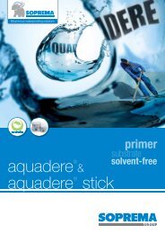
13.1 The membrane should be laid flat onto the substrate without folds or ripples, and fixed to the deck by fasteners<br />
and plates through the overlap of the membrane (see Figure 1).<br />
Figure 1 Application to steel decks<br />
7<br />
4<br />
6<br />
5<br />
4<br />
3<br />
2<br />
1<br />
1 Mechanical fixing<br />
2 Metal decking<br />
3 PUR/PIR insulation<br />
4 <strong>Flagon</strong> membrane<br />
5 Weld<br />
6 Weld seal<br />
7 Mechanical fixing with plate<br />
13.2 The position of the number of fasteners required must be in accordance with the fixing specifications provided by<br />
the Certificate holder.<br />
Page 6 of 10
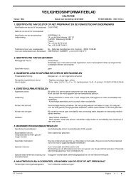
13.3 At a vertical flashing, and penetration of the roof, the horizontal membrane requires additional fixing bars (see<br />
Figure 2). On the perimeter the membrane must be secured against tearing by welding a 4 mm diameter PVC retaining<br />
cord to the membrane beyond the Flag Bar.<br />
Figure 2 Perimeter upstands<br />
12 11 10 9 13 8 7 6 5 4 1 3 9 2 14 10 9 8 7 11 6 5 4 3 2 6 12 1<br />
(1) Note: Upstands over 500 mm<br />
in height a Flag Bar will be<br />
mechanically fastened horizontally<br />
through the centre of the flashing<br />
and every 600 mm thereafter.<br />
150 mm min (1)<br />
1 Profiled flag metal capping, 1.4 mm thick<br />
2 <strong>Flagon</strong> membrane strip PVC <strong>SR</strong> welded to<br />
Flag metal capping to cover fixings<br />
3 Fixing at 250 mm centres<br />
4 Insulation to upstand<br />
5 PVC cord welded to field sheet direct<br />
behind Flag Bar<br />
6 Flag Bar fixed through all perimeter<br />
edges as per wind uplift calculation<br />
7 <strong>Flagon</strong> Flashing membrane PVC <strong>SR</strong><br />
8 Homogeneous manual welded lap<br />
9 <strong>Flagon</strong> PVC <strong>SR</strong> field sheet membrane,<br />
mechanically fastened to wind uplift schedules<br />
10 Insulation thickness to suit U-value<br />
11 Vaporflag vapour control layer, sealed at all laps<br />
with Flag Butyl Tape<br />
12 Profiled metal decking to engineers' specifications<br />
13 End profile<br />
14 Flag Butyl Tape<br />
*<br />
25 mm min<br />
Page 7 of 10<br />
(1) Note: Upstands over 500 mm<br />
in height a Flag Bar will be<br />
mechanically fastened horizontally<br />
through the centre of the flashing<br />
and every 600 mm thereafter.<br />
150 mm min (1)<br />
*<br />
25 mm min<br />
1 Profiled Flag metal drip edge, 1.4 mm thick<br />
2 Fixing at 250 mm centres<br />
3 PVC cord welded to field sheet direct behind Flag Bar<br />
4 Flag Bar fixed through all perimeter edges as per<br />
wind uplift calculation<br />
5 <strong>Flagon</strong> Flashing membrane PVC <strong>SR</strong><br />
6 Homogeneous manual welding<br />
7 <strong>Flagon</strong> PVC <strong>SR</strong> field sheet membrane,<br />
mechanically fastened to wind uplift schedules<br />
8 Insulation thickness to suit U-value<br />
9 Vaporflag vapour control layer, sealed at all laps<br />
with Flag Butyl Tape<br />
10 Profiled metal decking to engineers' specifications<br />
11 End profile<br />
12 Flag Butyl Tape<br />
13.4 For continuous fixing, the fixing bars should be positioned with a 10 mm gap to allow for expansion. Ends of<br />
the bars should be fixed with screws and Flag Bar End Protectors.<br />
Steel decks<br />
13.5 Steel decks must be manufactured from galvanized steel with a minimum thickness of 0.7 mm.<br />
13.6 Self-drilling and self-tapping screws should be selected in accordance with the Certificate holder’s instructions.<br />
Reinforced concrete decks<br />
13.7 Concrete decks will require pre-drilling. The diameter of the holes should not be less than 6 mm and nylon<br />
dowels or self-drilling anchors are recommended.<br />
13.8 When re-roofing on concrete decks, dowels must be anchored for their full length in solid concrete. This should<br />
be noted particularly when using cement screeds or intermediate layers.<br />
Timber decks<br />
13.9 Fixing bars should be positioned above and fixed to beams or joists. If this is not possible, fastening bars must<br />
be positioned across the direction of timber planks, provided the planks are sufficiently fastened to withstand the<br />
imposed wind loads.<br />
13.10 Fixing bars must be fixed by screws (nails are not suitable for this purpose), acceptable loads on each screw<br />
and corresponding space between screws in each case are calculated before installation.
14 Jointing and flashing procedure<br />
Hot-air welding (automatic welding machine)<br />
14.1 The welding area should be dry and clean. If the membrane in the weld area has become contaminated, it must<br />
be cleaned in accordance with the Certificate holder’s instructions.<br />
14.2 The overlap width of the membranes must be a minimum of 120 mm and spot welded, using a hand-held<br />
welder, every 150 to 200 mm along the length of the joint.<br />
14.3 The temperature for the automatic welding machine should be set in accordance with the Certificate holder’s<br />
instructions, depending on the thickness of the membrane and the ambient temperature.<br />
14.4 The joint is then welded using the machine. Care should be taken that overheating of the membrane does not<br />
occur; a possible impairment of the membrane may result.<br />
14.5 The seam should be tested with a suitable metal probe and any weakness repaired immediately.<br />
Hot-air welding (hand-held welder)<br />
14.6 The welding area should be dry and clean. If the membrane in the weld area has become contaminated, it must<br />
be cleaned in accordance with the Certificate holder’s instructions.<br />
14.7 The overlap width of the membranes must be a minimum of 120 mm and spot welded at approximately every<br />
400 mm along the length of the joint.<br />
14.8 The temperature for the hand-held welder should be set in accordance with the Certificate holder’s instructions,<br />
depending on the thickness of the membrane and the ambient temperature.<br />
14.9 The joint is then pre-welded parallel to, and behind, the main welding line. The pre-weld is tested for<br />
delamination prior the main welding being carried out.<br />
14.10 The main weld is then carried out. Care should be taken that overheating of the membrane does not occur; a<br />
possible impairment of the membrane may result.<br />
14.11 The seam should be tested with a suitable metal probe and any weakness repaired immediately.<br />
Flashing<br />
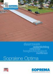
14.12 Flashing and detailing should be formed in accordance with the Certificate holder’s instructions (see Figure 3).<br />
Figure 3 Roof details<br />
1 2 3 4 5 6 7 8 9<br />
15 mm min.<br />
15 mm min.<br />
1 <strong>Flagon</strong> PVC <strong>SR</strong> field sheet membrane, mechanically<br />
fixed to wind uplift schedules<br />
2 Insulation thickness to suit U-value<br />
3 Flag Bar fixed around pipe (fixings as per wind uplift calculation)<br />
4 PVC cord welded to field sheet direct behind Flag Bar<br />
5 <strong>Flagon</strong> RW Outlet c/w gravel guard<br />
6 Clamping ring to secure membrane<br />
7 Homogeneous manual welded lap<br />
8 Vaporflag vapour control layer, sealed at all laps<br />
with Flag Butyl Tape<br />
9 Profiled metal decking to engineers' specifications<br />
Page 8 of 10<br />
1 2 3 4 5 6 7 8 9 10 11<br />
15 mm min.<br />
150 mm min<br />
1 Homogeneous manual welded lap<br />
2 <strong>Flagon</strong> preformed pipe collar<br />
3 Flag Bar fixed around pipe (fixings as per wind<br />
uplift calculation)<br />
4 PVC cord welded to field sheet direct behind Flag Bar<br />
5 Stainless steel banding<br />
6 Pipe<br />
7 Sealant<br />
8 <strong>Flagon</strong> PVC <strong>SR</strong> field sheet membrane, mechanically<br />
fixed to wind uplift schedules<br />
9 Insulation thickness to suit U-value<br />
10 Vaporflag vapour control layer, sealed at all laps<br />
with Flag Butyl Tape<br />
11 Profiled metal decking to engineers' specifications
15 Repair<br />
In the event of accidental damage, repairs can be carried out by cleaning the area around the damage and applying<br />
a patch as described in the Certificate holder’s instructions.<br />
Technical Investigations<br />
16 Tests<br />
16.1 An assessment was made of test data for <strong>Flagon</strong> <strong>SR</strong>1.2 and <strong>SR</strong>1.5 membranes to assess the following:<br />
Tests on the reinforcement<br />
mass per unit area<br />
tensile strength and elongation<br />
mesh number<br />
Tests on the membrane<br />
mass per unit area<br />
tensile strength and elongation at break<br />
nail tear resistance at 23°C, 40°C and –10°C<br />
dimensional stability<br />
low temperature foldability<br />
static indentation<br />
weight loss at elevated temperatures at 14 days, 28 days, 84 days and 168 days<br />
water absorption after 180 days water immersion<br />
wind uplift load per fixing<br />
water soak at 180 days immersion followed by dimensional stability<br />
168 days heat ageing at 80˚C followed by dimensional stability and low temperature foldability<br />
plasticiser content<br />
dehydrochlorination<br />
ash content<br />
Δ E colour change after UV exposure equal to 4500 MJ·m –2 of radiation energy.<br />
Tests on joints<br />
joint shear strength for hot-air welded joints and THF welded joints<br />
T-peel for hot-air welded joints and THF welded joints.<br />
16.2 Samples were taken from an existing site over 20 years old. The following comparison testing was carried on<br />
new product from the factory, site samples and site samples following additional UV ageing and results assessed:<br />
thickness<br />
mass per unit area<br />
low temperature foldability<br />
resistance to dynamic impact.<br />
16.3 Results of the root resistance tests on <strong>Flagon</strong> <strong>SR</strong>1.5 membranes, conducted by FLL, were assessed.<br />
17 Investigations<br />
17.1 Existing data on fire performance to BS 476-3 : 1958 of the reinforced membrane were evaluated.<br />
17.2 The manufacturing processes were examined, including methods of quality control. Details were also obtained<br />
of the quality and composition of the materials used.<br />
17.3 Wind uplift data on mechanically fixed systems from BDA Netherlands, tested in accordance with<br />
MOAT No 55 : 1991, were evaluated.<br />
17.4 Corrosion resistance test data from SM Darmstadt on the fixing screws and plates were evaluated in connection<br />
with durability.<br />
17.5 Fatigue resistance and creep stress data of the fixing screw’s polyamide sleeve were examined in connection<br />
with durability.<br />
17.6 An inspection visit to an existing site at least 20 years old was conducted.<br />
Page 9 of 10
Bibliography<br />
BS 476-3 : 1958 Fire tests on building materials and structures — External fire exposure roof test<br />
BS 6229 : 2003 Flat roofs with continuously supported coverings — Code of practice<br />
BS 8004 : 1986 Workmanship on building sites — Code of practice for waterproofing<br />
BS 8217 : 2005 Reinforced bitumen membranes for roofing — Code of practice<br />
BS EN 1991-1-1 : 2002 Eurocode 1 : Actions on structures — General actions— Densities, self-weight, imposed<br />
loads for buildings<br />
NA to BS EN 1991-1-1 : 2002 UK National Annex to Eurocode 1 : Actions on structures — General actions—<br />
Densities, self-weight, imposed loads for buildings<br />
BS EN 1991-1-3 : 2003 Eurocode 1 : Actions on structures — General actions — Snow loads<br />
NA to BS EN 1991-1-3 : 2003 UK National Annex to Eurocode 1 : Actions on structures — General actions —<br />
Snow loads<br />
BS EN 1991-1-4 : 2005 Eurocode 1 : Actions on structures — General actions — Wind actions<br />
NA to BS EN 1991-1-4 : 2005 UK National Annex to Eurocode 1 : Actions on structures — General actions —<br />
Wind actions<br />
Conditions of Certification<br />
18 Conditions<br />
18.1 This Certificate:<br />
relates only to the product/system that is named and described on the front page<br />
is issued only to the company, firm, organisation or person named on the front page — no other company, firm,<br />
organisation or person may hold or claim that this Certificate has been issued to them<br />
is valid only within the UK<br />
has to be read, considered and used as a whole document — it may be misleading and will be incomplete to be<br />
selective<br />
is copyright of the <strong>BBA</strong><br />
is subject to English Law.<br />
18.2 Publications, documents, specifications, legislation, regulations, standards and the like referenced in this Certificate<br />
are those that were current and/or deemed relevant by the <strong>BBA</strong> at the date of issue or reissue of this Certificate.<br />
18.3 This Certificate will remain valid for an unlimited period provided that the product/system and its manufacture<br />
and/or fabrication, including all related and relevant parts and processes thereof:<br />
are maintained at or above the levels which have been assessed and found to be satisfactory by the <strong>BBA</strong><br />
continue to be checked as and when deemed appropriate by the <strong>BBA</strong> under arrangements that it will determine<br />
are reviewed by the <strong>BBA</strong> as and when it considers appropriate.<br />
18.4 The <strong>BBA</strong> has used due skill, care and diligence in preparing this Certificate, but no warranty is provided.<br />
18.5 In issuing this Certificate, the <strong>BBA</strong> is not responsible and is excluded from any liability to any company, firm,<br />
organisation or person, for any matters arising directly or indirectly from:<br />
the presence or absence of any patent, intellectual property or similar rights subsisting in the product/system or any<br />
other product/system<br />
the right of the Certificate holder to manufacture, supply, install, maintain or market the product/system<br />
individual installations of the product/system, including their nature, design, methods, performance, workmanship<br />
and maintenance<br />
any works and constructions in which the product/system is installed, including their nature, design, methods,<br />
performance, workmanship and maintenance<br />
any loss or damage, including personal injury, howsoever caused by the product/system, including its manufacture,<br />
supply, installation, use, maintenance and removal.<br />
18.6 Any information relating to the manufacture, supply, installation, use, maintenance and removal of this product/<br />
system which is contained or referred to in this Certificate is the minimum required to be met when the product/system<br />
is manufactured, supplied, installed, used, maintained and removed. It does not purport in any way to restate the<br />
requirements of the Health and Safety at Work etc. Act 1974, or of any other statutory, common law or other duty<br />
which may exist at the date of issue or reissue of this Certificate; nor is conformity with such information to be taken as<br />
satisfying the requirements of the 1974 Act or of any statutory, common law or other duty of care.<br />
British Board of Agrément tel: 01923 665300<br />
Bucknalls Lane fax: 01923 665301<br />
Garston, Watford e-mail: mail@bba.star.co.uk<br />
Herts WD25 9BA ©2011<br />
website: www.bbacerts.co.uk<br />
Page 10 of 10