DE 61 GW - Appliances Online
DE 61 GW - Appliances Online
DE 61 GW - Appliances Online

You also want an ePaper? Increase the reach of your titles
YUMPU automatically turns print PDFs into web optimized ePapers that Google loves.
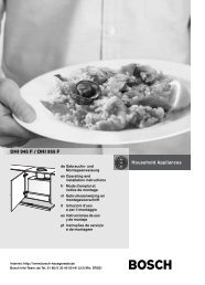
INSTALLATION and SERVICE INSTRUCTIONS<br />
USE and CARE INSTRUCTIONS<br />
<strong>DE</strong> <strong>61</strong> <strong>GW</strong><br />
DUAL FUEL COOKER<br />
distributed by<br />
DèLonghi<br />
Pty Ltd
2<br />
Dear Customer,<br />
Thank you for having purchased and given your<br />
preference to our product.<br />
The safety precautions and recommendations reported<br />
below are for your own safety and that of others. They<br />
will also provide a means by which to make full use of<br />
the features offered by your appliance.<br />
Please keep this booklet in a safe place. It may be<br />
useful in future, either to yourself or to others in the<br />
event that doubts should arise relating to its operation.<br />
This appliance must be used only for the task it has<br />
explicitly been designed for, that is for cooking<br />
foodstuffs. Any other form of usage is to be considered<br />
as inappropriate and therefore dangerous.<br />
The manufacturer declines all responsibility in the<br />
event of damage caused by improper, incorrect or<br />
illogical use of the appliance or be faulty installation.<br />
Important:<br />
This appliance is designed and manufactured solely for the cooking of domestic<br />
(household) food and is not suitable for any non domestic application and therefore<br />
should not be used in a commercial environment.<br />
The appliance guarantee will be void if the appliance is used within a non domestic<br />
environment i.e. a semi commercial, commercial or communal environment.<br />
PRODUCT LABEL
USING THE OVEN FOR THE FIRST TIME<br />
You are advised to carry out the following operations:<br />
■ Furnish the interior of the oven.<br />
■ Switch the empty oven ON at maximum temperature for about two hours<br />
to eliminate traces of grease and smell from the components.<br />
■ Disconnect the appliance from the electric power supply and clean the<br />
interior of the oven with a cloth soaked in water and neutral detergent<br />
and dry thoroughly.<br />
IMPORTANT PRECAUTIONS AND RECOMMENDATIONS FOR<br />
USE OF ELECTRICAL APPLIANCES<br />
Use of any electrical appliance implies the necessity to follow a series of fundamental<br />
rules. In particular:<br />
■ Never touch the appliance with wet hands or feet;<br />
■ Do not operate the appliance barefooted;<br />
■ The appliance is not intended for use by young children or infirm persons<br />
without supervision;<br />
■ Young children should be supervised to ensure they do not play with the<br />
appliance.<br />
The manufacturer cannot be held responsible for any damages caused by improper,<br />
incorrect or illogical use of the appliance.<br />
This cooker has been designed and constructed in accordance with the following<br />
codes and specifications:<br />
AGA101 (AS 4551) Approval Requirements for Domestic Gas cooking appliances<br />
AS/NZS 60335-1 General Requirements for Domestic electrical appliances<br />
AS/NZS 60335-2-6 Particular Requirements for Domestic electrical cooking appliances<br />
AS/NSZ 1044 Electromagnetic Compatibility Requirements.<br />
3
4<br />
IMPORTANT PRECAUTIONS AND RECOMMENDATIONS<br />
After having unpacked the appliance, check to ensure that it is not damaged.<br />
In case of doubt, do not use it and consult your supplier or a professionally qualified technician.<br />
Packing elements (i.e. plastic bags, polystyrene foam, nails, packing straps, etc.) should not be left<br />
around within easy reach of children, as these may cause serious injuries.<br />
■ Do not attempt to modify the technical characteristics of the appliance as this may become dangerous<br />
to use.<br />
■ Do not carry out cleaning or maintenance operations on the appliance without having previously<br />
disconnected it from the electric power supply.<br />
■ After use, ensure that the knobs are in the off position.<br />
■ The appliance is not intended for use by young children or infirm persons unless they have been<br />
adequately supervised by a responsible person to ensure that they can use the appliance safely.<br />
■ During and after use of the appliance, certain parts will become very hot. Do not touch hot<br />
parts. Care should be taken to avoid touching heating elements inside the oven.<br />
■ Keep children away from the appliance when it is in use.<br />
■ Young children should be supervised to ensure that they do not play with the appliance.<br />
■ Some appliances are supplied with a protective film on steel and aluminium parts. This film must<br />
be removed before using the appliance.<br />
■ Make sure that electrical cables connecting other appliances in the proximity of the cooker cannot<br />
come into contact with the hob or become entrapped in the oven door.<br />
■ Do not line the oven walls with aluminium foil. Do not place baking trays or the drip tray on the<br />
base of the oven chamber.<br />
■ WARNING When correctly installed, your product meets all safety requirements laid down for<br />
this type of product category. However special care should be taken around the rear or the<br />
underneath of the appliance as these areas are not designed or intended to be touched and<br />
may contain sharp or rough edges, that may cause injury.<br />
■ Fire risk! Do not store flammable material in the oven.<br />
■ Always use oven gloves when removing the shelves and food trays from the oven whilst hot.<br />
■ Do not hang towels, dishcloths or other items on the appliance or its handle – as this could be a<br />
fire hazard.<br />
■ Clean the oven regularly and do not allow fat or oils to build up in the oven base or tray.<br />
Remove spillages as soon as they occur.<br />
■ Do not stand on the open oven door.<br />
■ Always stand back from the appliance when opening the oven door to allow steam and hot air<br />
to escape before removing the food.<br />
■ This appliance is for domestic use only.<br />
■ Safe food handling: leave food in the oven for as short a time as possible before and after cooking.<br />
This is to avoid contamination by organisms which may cause food poisoning. Take particular<br />
care during warmer weather.<br />
■ The manufacturer declines all liability for injury to persons or damage to property caused by<br />
incorrect or improper use of the appliance.<br />
■ WARNING: Taking care NOT to lift the oven by the door handle.<br />
■ IMPORTANT NOTE: This appliance shall not be used as a space heater, especially<br />
if installed in marine craft or caravans.
CAUTION:<br />
INSTALLATION<br />
■ This appliance must be installed in accordance with these installation<br />
instructions.<br />
■ This appliance shall only be serviced by authorized personnel.<br />
■ This appliance is to be installed only by an authorised person.<br />
■ Incorrect installation, for which the manufacturer accepts no responsibility,<br />
may cause personal injury of damage.<br />
■ Always disconnect the cooker from mains power supply before carrying out<br />
any maintenance operations or repairs.<br />
■ In the room where the cooker is installed, there must be enough air to<br />
allow the gas to burn correctly, according to the current local regulations.<br />
ELECTRICAL REQUIREMENTS<br />
■ The appliance must be connected to the mains checking that the voltage corresponds<br />
to the value given in the rating plate and that the electrical cable sections<br />
can withstand the load specified on the plate.<br />
■ The plug must be connected to an earthed socket in compliance with safety<br />
standards.<br />
■ If the appliance is supplied without a plug, fit a standard plug which is suitable<br />
for the power consumed by the appliance.<br />
■ The appliance must be connected directly to the mains placing a two pole<br />
switch with minimum opening between the contacts of 3 mm between the<br />
appliance and the mains.<br />
■ The power supply cable must not touch the hot parts and must be positioned so<br />
that it does not exceed 50°C above ambient.<br />
■ Once the appliance has been installed, the switch or socket must always be<br />
accessible.<br />
■ If the supply cord is damaged it must be replaced by the manufacturer or<br />
it’s Service Agent or a similarly qualified person in order to avoid a hazard.<br />
WARNING: This cooker must be connected to electrical supply using<br />
V105 insulated cable.<br />
N.B. The connection of the appliance to earth is mandatory.<br />
If the installation requires alterations to the domestic electrical system call a qualified<br />
electrician. He should also check that the socket cable section is suitable for the power<br />
drawn by the appliance.<br />
Appliance power rating:<br />
230 V~ 2460 W (10.6 A)<br />
240 V~ 2680 W (11.1 A)<br />
Replacing the power cord must be done by a qualified electrician in accordance<br />
with the instructions supplied by the manufacturer and in compliance<br />
with established electrical regulations.<br />
5
6<br />
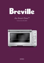
CLEARANCES<br />
Installation clearances and protection of combustible surfaces shall comply with the<br />
current local regulations eg. AG 601 (AS 5601) Gas Installations code.<br />
Installation shall comply with the dimension in Fig. 1 bearing in mind that.<br />
Overhead Clearances<br />
In no case shall the clearances between the highest part of the cooker be less than<br />
600 mm or for an overhead exhaust fan 750 mm. AII other downward facing combustible<br />
surfaces less than 600 mm above the cooker surface shall be protected for the<br />
full width of the cooking surface in accordance with the standards noted above. In no<br />
case shall the clearance be less than 450 mm.<br />
Rear and Side Clearances<br />
Where the dimensions from the periphery of the nearest burner to any vertical combustible<br />
surface is less than 200 mm the surface shall be protected in accordance with<br />
the standards to a height of not less than 150 mm above the cooking surface for the<br />
full width or depth of the cooking surface<br />
Where the dimensions from the periphery of the nearest burner to any horizontal combustible<br />
surface is less than 200 mm, the horizontal surface shall be greater than<br />
10 mm below the surface of the hob, or the horizontal surface requirement above.<br />
Protection of combustible surfaces.<br />
The standards above specify that where required protection shall ensure that the surface<br />
temperature of the combustible surface does not exceed 65 °C above room temperature.<br />
If the cooker is located on a pedestal it is necessary to provide safety measures<br />
to prevent falling out.<br />
750 mm<br />
500 mm<br />
450 mm<br />
105 mm<br />
Figure 1<br />
Cooker overall dimensions [mm]<br />
• height: min 900 - max 915<br />
• width: 600<br />
• depth: 600
LEVELLING THE COOKER<br />
The cooker is equipped with 4 levelling feet and may be levelled by screwing or<br />
unscrewing the feet with a spanner (fig. 4).<br />
It is important to observe the prescriptions of figures 2a, 2b, 3.<br />
+ 8<br />
0 mm<br />
+ 8 mm<br />
+ 15 mm<br />
Figure 2a Figure 3<br />
Figure 2b<br />
Supplied with the cooker<br />
in a separate kit<br />
Figure 4<br />
7
8<br />
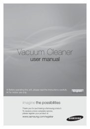
ANTI-TILT BRACKET<br />
Important!<br />
To restrain the appliance and prevent it tipping accidentally, the anti-tilt<br />
bracket must be fitted according to the instructions below.<br />
1. Drill four 8mm diameter holes for the fixing screws (two in the wall and two in the<br />
floor - see Fig. 5) and insert the plastic plugs supplied.<br />
Important! Before drilling the holes, check that you will not damage any<br />
pipes or electrical wires.<br />
2. Attach the anti-tilt bracket to the floor and rear wall using the four screws supplied,<br />
as shown in Fig. 5.<br />
3. After attaching the anti-tilt bracket securely, slide the cooker close to the anti-tilt<br />
bracket and vertically fit the rear right foot into the circular opening of the bracket by<br />
lifting the rear of the cooker. Then slide cooker into place.<br />
Ensure that the rear right foot slides under the bracket, as shown in Fig. 5.<br />
IMPORTANT NOTE: if necessary adjust the height of the feet to ensure the rear<br />
right foot slides under the anti-tilt bracket.<br />
Figure 5<br />
Dotted line showing the position<br />
of the cooker when installed<br />
= =<br />
260<br />
Foot of cooker<br />
Attaching the anti-tilt bracket and sliding the cooker into place<br />
Anti-tilt<br />
bracket
GAS SUPPLY:<br />
■ The connection must be performed by an authorised person according to the<br />
relevant standards.<br />
■ Before connecting the appliance to the gas main, mount the brass conical adaptor<br />
onto the gas inlet pipe, upon which the gasket has been placed (figs. 6-7).<br />
Conical adaptor and gasket are supplied with the appliance (packed with conversion<br />
kit for use with Natural gas or ULPG).<br />
■ This appliance is suitable for use with Natural Gas or ULPG. (Check the “gas<br />
type” sticker attached to the appliance).<br />
■ For Natural Gas models the gas supply is connected to the pressure regulator<br />
which is supplied with the appliance (fig. 7). Adjust the regulator to obtain a test<br />
point pressure of 1 kPa with the two semi-rapid (SR) burners operating at maximum.<br />
■ For ULPG models the gas supply is connected to the test point adaptor which is<br />
supplied with the appliance (fig. 6) and ensure that the supply pressure is regulated<br />
to 2.75 kPa.<br />
■ The connection must be made at the rear of appliance (left or right); the pipe<br />
does not cross the cooker.<br />
■ The inlet not used must be closed off with the cap and sealing gasket supplied.<br />
■ IMPORTANT: Use two spanners to tighten or loosen the connecting pipe (fig. 8)<br />
Test<br />
point<br />
Figure 6<br />
Gas connection for<br />
ULPG<br />
Gas inlet pipe<br />
Nipple<br />
Gasket<br />
Brass conical adaptor<br />
(Thread tight: use<br />
suitable seal)<br />
Test point adaptor<br />
Test<br />
point<br />
Figure 7<br />
Gas connection for<br />
NATURAL GAS<br />
Gas inlet pipe<br />
Nipple<br />
Gasket<br />
Brass conical adaptor<br />
(Thread tight: use<br />
suitable seal)<br />
Gas regulator<br />
9
10<br />
1. After connecting the gas supply, check the piping and connections for leaks using<br />
a soap and water solution. The presence of bubbles indicates a leak, tighten or<br />
replace connections as appropriate.<br />
Warning: Do not use any naked flame to check for leaks.<br />
2. Adjust the test point pressure or supply pressure to the value which is appropriate<br />
for the gas type.<br />
3. The operation of the appliance must be tested when installation is completed.<br />
4. Turn on the appliance gas controls and light each burner individually and in combination.<br />
Check for a well defined blue flame without any yellow tipping. If any<br />
abnormality is evident then check that the burner cap is located properly and the<br />
injector nipple is aligned correctly.<br />
5. Check the minimum burner setting by quickly rotating the gas control knob from<br />
the maximum to the minimum position, the flame must not go out. If adjustment is<br />
required carry out the “minimum burner setting adjustment" procedure described<br />
6. If satisfacfory performance cannot be obtained, the installer shall check the installation<br />
and notify the local gas supply authority for a gas supply problem, or if it is an<br />
appliance problem, our Customer Service Centre should be called to obtain the<br />
nearest authorized Delonghi Service Agent.<br />
WARNING, This appliance IS NOT SUITABLE for installation with a hose<br />
assembly.<br />
Figure 8 Figure 9<br />
Plug
CONVERSION PROCEDURE (to convert to Natural gas or to ULPG)<br />
REPLACING THE INJECTORS<br />
This appliance is suitable for use with Natural gas or ULPG (check the “gas type” sticker<br />
attached to the appliance). A label stating the type of gas used after replacing the<br />
injectors must be attached at the rear of the appliance, in proximity of the gas inlet<br />
connection. The nominal gas consumption and injector size details are provided in<br />
table at page 13.<br />
To replace the injectors proceed as follows:<br />
■ Remove pan supports and burners from the cooktop.<br />
■ Using a spanner, remove the injector J (figs. 10-11) and replace it with one<br />
according to the gas type (see following tables - page 13).<br />
■ Affix to the rear of the appliance, in proximity of the gas inlet connections, the<br />
warning label (supplied with the conversion kit) stating that the cooker has<br />
been converted for use with ULPG / Natural gas.<br />
IMPORTANT<br />
■ If the cooker is suitable for use with Natural gas and must be converted for use<br />
with ULPG, before connecting to gas main remove the appliance gas regulator<br />
and replace with test point adaptor (see figs. 6-7)<br />
■ If the cooker is suitable for use with ULPG and must be converted for use with<br />
Natural gas, before connecting to the gas main remove the appliance test point<br />
adaptor and replace with gas regulator (see figs. 6-7).<br />
NOTE:<br />
Gas regulator and test point adaptor are supplied with the appliance (packed with<br />
conversion kit)<br />
The burners are designed so that regulation of primary air is not required.<br />
Figure 10 Figure 11<br />
J<br />
J<br />
11
12<br />
MINIMUM BURNER SETTING ADJUSTMENT<br />
Check whether the flame spreads to all burner ports when the burner is lit with the gas<br />
tap set to the minimum position. If some ports do not light, increase the minimum gas<br />
rate setting.<br />
Check whether the burner remains lit even when the gas tap is turned quickly from<br />
the maximum to the minimum position. If the burner does not remain lit, increase the<br />
minimum gas rate setting.<br />
The procedure for adjusting the minimum gas rate setting is described below.<br />
■ Turn on the burner<br />
■ Turn the tap to the MINIMUM position<br />
■ Take off the knob<br />
■ With a small flat screwdriver turn the screw inside the tap rod to the correct regulation<br />
(fig. 12).<br />
Normally for ULPG, the regulation screw is tightened up.<br />
Figure 12
TABLE FOR THE CHOICE OF THE INJECTORS<br />
Natural gas ULPG<br />
Test Point Pressure [kPa] 1.0 2.75<br />
BURNER<br />
Injector<br />
Orifice Dia.<br />
[mm]<br />
Gas<br />
Consumption<br />
[MJ/h]<br />
Injector<br />
Orifice Dia.<br />
Gas<br />
Consumption<br />
[MJ/h]<br />
Auxiliary (A) 0.85 3.60 0.53 3.60<br />
Semi-rapid (SR) 1.12 6.30 0.70 6.30<br />
Triple ring (TC) 1.65 13.30 0.95 11.90<br />
LUBRICATION OF THE GAS TAPS<br />
If the gas tap becomes stiff, it is necessary to dismantle it carefully and clean it with<br />
petroleum spirit. Specialist high temperature resistant grease should be used to<br />
lubricate the tap before replacing.<br />
The operations must be carried out by an authorised person/service agent.<br />
Figure 13<br />
[mm]<br />
13
14<br />
CAUTION:<br />
USE and CARE<br />
■ This appliance must be used only for the task it has explicitly been designed for,<br />
that is for domestic cooking of foodstuffs. Any other form of usage is to be considered<br />
as inappropriate and therefore dangerous.<br />
■ Do NOT place combustible materials or products on this appliance at any time.<br />
■ Do NOT spray aerosols in the vicinity of this appliance while it is in use.<br />
Figure 14<br />
Figure 15
USING THE OVEN FOR THE FIRST TIME<br />
■ Clean the inside of the oven with a cloth soaked in water and neutral detergent<br />
and dry thoroughly.<br />
■ Slide in the wire racks on the oven wall as in Fig. 14.<br />
■ Slide in the grease filter on the back of the oven as in Fig. 16.<br />
■ Position the shelf and tray as per Fig. 15.<br />
■ To eliminate traces of grease in manufacture it is necessary to pre-heat the oven<br />
at the maximum temperature.<br />
• For 60 minutes in the position, and for another 15 minutes in the position.<br />
GREASE FILTER<br />
■ A special screen is provided at the back of the oven to catch grease particles,<br />
mainly when meat is being roasted (fig. 16).<br />
■ When baking pastry etc. this filter should be removed.<br />
■ Always clean the filter after cooking as any solid residues on it might adversely<br />
affect the oven performance.<br />
Figure 16<br />
15
16<br />
GAS HOB<br />
Figure 17<br />
2 3<br />
1<br />
GAS BURNERS Natural Gas ULPG<br />
MJ/h MJ/h<br />
1. Auxiliary burner (A) 3.6 3.6<br />
2. Semi-rapid burner (SR) 6.3 6.3<br />
3. Semi-rapid burner (SR) 6.3 6.3<br />
4. Triple ring burner (TC) 13.3 11.9<br />
4
LIGHTING GAS BURNERS<br />
FITTED WITH ELECTRONIC IGNITION<br />
■ Check that the electricity is<br />
switched on to allow spark ignition.<br />
■ Make sure that all controls are<br />
turned to zero.<br />
■ The gas flow to the burners is<br />
controlled by taps. The switch for<br />
the electric ignition is incorporated<br />
in the knobs.<br />
■ You control the flow by turning<br />
the knob indicator to line up<br />
with the following symbols:<br />
– Symbol 0 : tap closed (burner off)<br />
– Symbol : High (maximum)<br />
– Symbol : Low (minimum)<br />
Figure 18<br />
■ To ignite automatically, push the required knob down and turn it to maximum,<br />
keeping the knob down until the burner lights.<br />
■ You can control the temperature by the knob to “High” (maximum) from “Low”<br />
(minimum).<br />
■ To switch off, turn the knob clockwise until you hear the safety click.<br />
■ Note that, if you are using a burner at the minimum setting, you turn the knob<br />
clockwise past the maximum setting before reaching the off position.<br />
■ Whenever the lighting of the burners is difficult due to peculiar conditions of<br />
the gas features or supply, it is advised to repeat the ignition with the knob on<br />
“minimum” position.<br />
■ If when lighting any of the burners an abnormal flame appears, switch the<br />
burner off and relight using the minimum setting.<br />
■ If the flame is still not correct, turn the burner off and call our Customer Service<br />
center for your nearest Authorized Delonghi Service Agent.<br />
■ In the case of a mains failure light the burner with a match or lighted taper.<br />
17
18<br />
CHOICE OF BURNER<br />
The burner must be chosen according to the diameter of the pans and energy<br />
required.<br />
For optimum efficiency use a wok or pan no smaller than 230mm diameter.<br />
Figure 19<br />
do not use pans with concave or convex bases<br />
Burners Pan diameter<br />
Auxiliary 12 - 14 cm<br />
Semi-rapid 16 - 24 cm<br />
Triple ring 26 - 28 cm<br />
Wok max 36 cm<br />
Saucepans with handles which are excessively heavy, in relationship to the weight of<br />
the pan, are safer as they are less likely to tip.<br />
Pans which are positioned centrally on burners are more stable than those which are<br />
offset.<br />
It is far safer to position the pan handles in such a way that they cannot be accidentally<br />
knocked.<br />
When deep fat frying fill the pan only one third full of oil.<br />
DO NOT cover the pan with a lid and DO NOT leave the pan unattended.<br />
In the unfortunate event of a fire, leave the pan where it is and turn off all controls.<br />
Place a damp cloth or correct fitting lid over the pan to smother the flames.<br />
DO NOT use water on the fire.<br />
Leave the pan to cool for at least 30 minutes.
CORRECT USE OF TRIPLE-RING BURNER<br />
■ The flat-bottomed pans are to be placed directly onto the pan-support.<br />
■ To use the WOK, you must place the wok stand in the CORRECT position as<br />
shown in Figs. 20-21.<br />
IMPORTANT:<br />
The special grille for wok pans (fig. 21) MUST BE PLACED ONLY over the pan-rest for<br />
the triple-ring burner.<br />
Figure 20 Figure 21<br />
WRONG CORRECT<br />
19
20<br />
PLURIFUNCTION ELECTRIC OVEN<br />
8<br />
7 6 5<br />
CONTROL PANEL<br />
Controls description<br />
1. Front right burner control knob<br />
2. Rear right burner control knob<br />
3. Rear left burner control knob<br />
4. Front left burner control knob<br />
5. 120’ timer<br />
6. Plurifunction oven thermostat knob<br />
7. Plurifunction oven switch knob<br />
4 3 2 1<br />
Note: The electric ignition of the hob burners is incorporated in the knobs.<br />
Pilot lamp:<br />
8. Oven thermostat indicator light<br />
GENERAL FEATURES<br />
Figure 22<br />
With your new Plurifunction oven it is possible to cook a variety of food using the 4 different<br />
cooking functions.<br />
The 4 positions, thermostatically controlled, are obtained by 3 heating elements.<br />
Please note: This appliance incorporates a safety cooling fan which you will hear<br />
operating whenever the oven or grill are in use. This fan is to reduce the external<br />
temperature of the appliance and cool the internal components.
OPERATING PRINCIPLES<br />
Heating and cooking in the fan assisted oven are obtained in the following ways:<br />
a. by normal convection<br />
The heat is produced by the upper and lower heating elements.<br />
b. by forced semi-convection<br />
The heat produced by the top and bottom heating elements is distributed throughout<br />
the oven by the fan.<br />
c. by radiant heat<br />
The food is grilled by the infra red grill element.<br />
d. by radiant heat and ventilation<br />
The food is grilled by the grill element is distributed throughout the oven.<br />
e. by ventilation<br />
The food is defrosted by using the fan only function without heat.<br />
WARNING:<br />
The door is hot, use the handle.<br />
ATTENTION - MOST IMPORTANT<br />
Pay special attention not to touch the hot heating element inside the oven<br />
cavity.<br />
Figure 23<br />
THERMOSTAT KNOB<br />
This only sets the cooking temperature and does not switch the oven on. Rotate<br />
clockwise until the required temperature is reached (from 50 to 250°C).<br />
21
22<br />
FUNCTION SELECTOR KNOB<br />
Rotate the knob clockwise to set the oven for one of the following functions.<br />
OVEN LIGHT<br />
By setting the knob to this position, only the oven light comes on.<br />
It remains on in all the cooking modes.<br />
TRADITIONAL BAKE<br />
The upper and lower heating elements come on. The heat being dispersed by<br />
natural convection. The temperature range must be set between 50 °C and<br />
250 °C using the thermostat.<br />
The oven must be preheated before cooking.<br />
Ideal for:<br />
Food that requires the same degree of cooking both inside and out, for example<br />
roasts, spare pork ribs, meringues etc.<br />
FAN ASSISTED BAKE<br />
The upper and lower heating elements come on and the fan come on - the heat from<br />
the element being circulated by the fan.<br />
The temperature range can be set to between 50 °C and 250 °C using the thermostat.<br />
Idea for:<br />
Large bulky quantities of food that require even cooking throughout for example large<br />
roasts, turkey, roast turkey, cakes etc.<br />
<strong>DE</strong>FROST<br />
With the thermostat knob on “0” only the oven fan is on.<br />
The food is thawed by ventilation without heating.<br />
Ideal for:<br />
Quick thawing of frozen foods; one kg requires approximately 1 hour.<br />
Thawing times vary according to the quantity and type of food to be thawed.
FAN GRILL<br />
Both the grill and the fan come on. Most of the cooking is done by grilling and then<br />
the hot air circulated around the oven. The oven door should be kept closed.<br />
The temperature can be set between 50 °C and 175 °C maximum.<br />
The oven should be preheated for 5 minutes before cooking. For further cooking hints<br />
see “GRILLING AND COOKING AU GRATIN”.<br />
Ideal for:<br />
Quick sealing in of food juices for example such as hamburger, chicken pieces, chops.<br />
It is recommended that you do not grill for longer than 30 minutes at any<br />
one time.<br />
Attention: the oven door becomes very hot during operation.<br />
Keep children away.<br />
GRILLING<br />
The infrared grill element at the top of the oven comes on. The heat is dispersed by<br />
radiation.<br />
Use with the oven door closed and the thermostat knob to position 225 °C for max<br />
15 minutes, then to position 175 °C.<br />
For cooking hints, see the chapter “USE OF THE GRILL”.<br />
Ideal for:<br />
Intense grilling, browning, cooking au gratin and toasting etc.<br />
It is recommended that you do not grill for longer than 30 minutes at any<br />
one time.<br />
Attention: the oven door becomes very hot during operation.<br />
Keep children away.<br />
23
24<br />
COOKING ADVICE<br />
STERILIZATION<br />
Sterilization of foods to be conserved, in full and hermetically sealed jars, is done in the<br />
following way:<br />
a. Set the switch to position .<br />
b. Set the thermostat knob to position 185 °C and preheat the oven.<br />
c. Fill the dripping pan with hot water.<br />
d. Set the jars onto the dripping pan making sure they do not touch each other and<br />
the door and set the thermostat knob to position 135 °C.<br />
When sterilization has begun, that is, when the contents of the jars start to bubble,<br />
turn off the oven and let cool.<br />
Check your recycle book for full instructions.<br />
SIMULTANEOUS COOKING OF DIFFERENT FOODS<br />
The oven set on position can cook several different foods together. Foods as<br />
diverse as fish and cakes can be cooked together without the cross transference of<br />
flavours. This is because the fats and cooking smell that would normally be<br />
deposited on the different foods are oxidised and are not absorbed by the foods.<br />
The cooking temperature of the foods, however must be within 20 - 25°C of each<br />
other. The food with the longest cooking time will be put into the oven first and<br />
the other foods are added as necessary according to their cooking times.<br />
ROASTING<br />
To obtain classical roasting, it is necessary to remember:<br />
■ that it is advisable to maintain a temperature between 180 °C and 200 °C.<br />
■ that the cooking time depends on the quantity and the type of foods.
GRILLING AND COOKING AU GRATIN<br />
As the hot air completely covers the food to be cooked, grilling may be done with<br />
the food on rack in the oven. The knob should be switched to position .<br />
The thermostat should be set to 175 °C and the oven pre-heated.<br />
The food should be placed on a rack in the oven for the required cooking time.<br />
Adding a few dabs of butter before the end of the cooking time gives the golden “au<br />
gratin” effect.<br />
It is recommended that you do not grill for longer than 30 minutes at<br />
any one time.<br />
Caution: the oven door becomes very hot during operation. Keep children<br />
well out of reach.<br />
USE OF THE GRILL<br />
Preheat the oven for about 5 minutes.<br />
Introduce the food to be cooked, positioning the rack as close to the grill as<br />
possible.<br />
The dripping pan should be placed under the rack to catch the cooking juices<br />
and fats.<br />
Grilling with the oven door closed.<br />
Do not grill for longer than 30 minutes at any one time.<br />
Caution: the oven door becomes very hot during operation. Keep children<br />
well out of reach.<br />
WARNING: Accessible parts may become hot when the grill is used.<br />
Children should be kept away.<br />
25
26<br />
RECOMMEN<strong>DE</strong>D COOKING TEMPERATURE<br />
Food °C °F Gas Shelf Cooking<br />
Mark Position* Time (approx)<br />
CAKES<br />
Victoria sandwich 190 375 5 2 or 3 20-25 mins<br />
Small cakes/buns 190 375 5 1 and 2 15-20 mins<br />
Maidera cake 180 350 4 2 or 3 20 mins<br />
Fruit cake 170 325 3 3 1 3 /4 hours<br />
Rich fruit cake 150 300 2 3 or 4 2 1 /2 hours<br />
Scones 225 425 8-9 2 8-10 mins<br />
PASTRY<br />
Puff 225 425 8-9 2 10-20 mins<br />
Short crust 200 400 6 2 20-30 mins<br />
Plate tarts 200-210 400-410 6 1 or 2 30-35 mins<br />
Quiches and flans 200-210 400-410 6 1 or 2 40-45 mins<br />
YEAST<br />
Bread loaf 225 425 7-8 2 35-55 mins<br />
Bread rolls 220 425 7 1 or 2 15-20 mins<br />
Pizza dough 230 450 8 2 20 mins<br />
ROAST MEAT<br />
Beef – Medium 190 375 5 2 or 3 20 mins/lb + 20 mins<br />
Lamb 190 375 5 2 or 3 25-30 mins/b + 25 mins<br />
Pork 190-200 375-400 5-7 2 or 3 30 mins/lb + 30 mins<br />
Veal 190 375 5 2 or 3 30 mins/b + 30 mins<br />
Chicken 190 375 5 2 or 3 30 mins/b + 30 mins<br />
Turkey up to 10lb 180 350 4 2 or 3 18-20 mins/b + 20 mins<br />
Stews/casseroles 150-170 300-325 2-3 2 or 3 1 1 /2 2 hours<br />
N.B. For fan ovens reduce the temperature<br />
by 10-20°C. For any dish taking one hour or<br />
over to cook, reduce the cooking time by 10<br />
minutes per hour.<br />
* Shelf positions have been counted from<br />
the top of the oven to the base.<br />
A fan oven creates more even temperature<br />
throughout, therefore the shelf positions are<br />
not as critical.
TIMER (Fig. 24)<br />
The timer runs the oven for a preset time.<br />
How to use the timer<br />
1) Starting up<br />
After setting the function selector and thermostat to the required mode and temperature,<br />
rotate the timer knob clockwise until you reach the required cooking time<br />
(max 120 minutes).<br />
Once this time has elapsed, the timer will return to the “0” position and the oven will<br />
automatically switch off.<br />
2) Manual position.<br />
If the cooking time is longer than two hours or if you wish to use the oven manually,<br />
switching it off as required, the knob must be turned to position .<br />
Figure 24<br />
27
28<br />
Maintenance<br />
Period<br />
GENERAL ADVICE<br />
■ Before you begin cleaning, you must ensure that the appliance is<br />
switched off.<br />
■ It is advisable to clean when the appliance is cold and especially when<br />
cleaning the enamelled parts.<br />
■ Avoid leaving alkaline or acidic substances (lemon juice, vinegar, etc.) on the<br />
surfaces.<br />
■ Avoid using cleaning products with a chlorine or acidic base.<br />
■ Do not use a steam cleaner because the moisture can get into the<br />
appliance thus make it unsafe.<br />
ENAMELLED PARTS<br />
All the enamelled parts must be cleaned with a sponge and soapy water only or other<br />
non-abrasive products.<br />
Dry preferably with a microfibre or soft cloth.<br />
STAINLESS STEEL SURFACES<br />
The stainless steel front panels on this cooker (facia, bottom panel) are protected by a<br />
finger-print proof lacquer. To avoid damaging this lacquer, do not clean the stainless<br />
steel with abrasive cleaners or abrasive cloths or scouring pads.<br />
ONLY SOAP/WARM WATER MUST BE USED TO CLEAN THE STAINLESS STEEL<br />
SURFACES.<br />
GAS TAPS<br />
Cleaning and Maintenance<br />
Description<br />
Daily • Clean gas cooktop as per instructions below<br />
Monthly<br />
3 - 4 Yearly<br />
• Remove burner caps, burner rings & base and clean using<br />
non abrasive detergent & rinse in cold water & dry thoroughly<br />
before replacing back on hob<br />
• Clean ignitor tip using damp soapy cloth and dry thoroughly<br />
• Contact your local authorized gas Service Agent to perform<br />
a thorough check on all gas components on the gas cooker<br />
If the gas taps are not working properly, call our Customer Service Centre to obtain the<br />
nearest Authorized Delonghi Service Agent.
INSI<strong>DE</strong> OF OVEN<br />
■ The oven should always be cleaned after use when it has cooled down.<br />
The cavity should be cleaned using a mild detergent solution and warm water.<br />
Suitable proprietary chemical cleaners may be used after first consulting with the<br />
manufacturers recommendations and testing a small sample of the oven cavity.<br />
Abrasive cleaning agents or scouring pads/cloths should not be used on the cavity<br />
surface.<br />
■ NOTE: The manufacturers of this appliance will accept no responsibility for damage<br />
caused by chemical or abrasive cleaning.<br />
■ Do not store flammable material in the oven.<br />
GRILL HEATING ELEMENT<br />
■ The heating element is self-cleaning and does not require maintenance.<br />
GREASE FILTER<br />
■ Clean the filter after any cooking! The grease filter can be removed for cleaning<br />
and should be washed regularly in hot soapy water (fig. 16).<br />
■ Always dry the filter properly before fitting it back into the oven.<br />
REPLACING THE OVEN LIGHT BULB<br />
Switch the cooker off at the mains.<br />
When the oven is cool, unscrew and replace the bulb with another one resistant to<br />
high temperatures (300°C), voltage 230-240 V~ (50 Hz), E14 and same power (check<br />
watt power as stamped in the bulb itself) of the replaced bulb.<br />
Note: Oven bulb replacement is not covered by your guarantee.<br />
OVEN DOOR<br />
The internal glass of the oven door can<br />
be easily removed for cleaning by<br />
unscrewing the two lateral fixing<br />
screws (fig. 25).<br />
Attention: Do not store flammable<br />
material in the oven.<br />
Figure 25<br />
29
30<br />
BURNERS<br />
They can be removed and washed only with<br />
soapy water.<br />
Detergents can be used but must not be abrasive<br />
or corrosive.<br />
Do not use abrasive sponges or pads.<br />
Do not put in dishwasher.<br />
After cleaning, make sure that the burner-caps,<br />
as well as the burners, have been well wiped<br />
off and CORRECTLY POSITIONED.<br />
It is essential to check that the burner flame distributor<br />
F and the cap C has been correctly<br />
positioned (see fig. 26) - failure to do so can<br />
cause serious problems.<br />
Check that the electrode “S” (fig. 26) is always<br />
clean to ensure trouble-free sparking.<br />
Note:<br />
The electrode “S” must be very carefully<br />
cleaned.<br />
To avoid damage to the electric ignition<br />
do not use it when the burners are not in<br />
place.<br />
TRIPLE RING BURNER<br />
C<br />
F<br />
Figure 26<br />
The triple ring burner must be correctly positioned (see fig. 27); the burner rib must be<br />
located in position as shown by the arrow.<br />
The burner correctly positioned must not rotate (fig. 28).<br />
Then position the cap A and the ring B (fig. 28).<br />
Figure 27 Figure 28<br />
A B<br />
S
REMOVING THE OVEN<br />
DOOR - Type “A”<br />
The oven door can easily be removed<br />
as follows:<br />
■ Open the door to the full extent<br />
(fig. 30).<br />
■ Attach the retaining rings to the<br />
hooks on the left and right<br />
hinges (fig. 31).<br />
■ Hold the door as shown in fig.<br />
29.<br />
■ Gently close the door and withdraw<br />
the lower hinge pins from<br />
their location (fig. 32).<br />
■ Withdraw the upper hinge pins<br />
from their location (fig. 33).<br />
■ Rest the door on a soft surface.<br />
■ To replace the door, repeat the<br />
above steps in reverse order.<br />
Figure 29<br />
Figure 30<br />
Figure 31<br />
Figure 32<br />
Figure 33<br />
31
32<br />
REMOVING THE OVEN<br />
DOOR - Type “B”<br />
To facilitate oven cleaning, it is possible<br />
to remove the door.<br />
Please follow the instructions carefully:<br />
■ Open the door completely.<br />
■ Push down the lever “L” (fig. 34) and,<br />
keeping it in this position, slowly<br />
close the door in order to block the<br />
hinge.<br />
■ Grip the door (as indicated in fig. 35)<br />
and, while closing it, release the two<br />
hinges as shown in fig. 36.<br />
DOOR ASSEMBLY<br />
■ Grip the door with your hands<br />
placed near the hinges and raise the<br />
levers “H” with your forefingers (fig.<br />
36).<br />
■ Insert the hinges in their position until<br />
levers “H” are hooked.<br />
■ Open the door completely to obtain<br />
the release of levers “L”.<br />
Figure 34<br />
H<br />
L<br />
Figure 35<br />
Figure 36
Service and Maintenance<br />
If the ignition spark fails to ignite or does not light the gas, check the following<br />
items before calling our Customer Service Centre to obtain the nearest Authorised<br />
Service Agent:<br />
■ Burner is reassembled and located correctly.<br />
■ Spark electrode and white ceramic are clean and dry.<br />
■ 240 VAC power supply is connected.<br />
Contact the local gas utility or our Customer Service Centre to obtain the nearest<br />
Authorized Service Agent.<br />
■ You can smell gas when all burners are turned on.<br />
■ The burners do not remain alight at the minimum marked setting.<br />
■ The burner flame is yellow or emits an unusual odour.<br />
Note that a bi-annual inspection of the appliance by an authorized service agent<br />
or your locate gas utility will ensure many years of trouble free operation of your<br />
appliance.<br />
33
34<br />
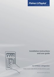
WIRING DIAGRAM<br />
CC<br />
ELECTRIC DIAGRAM KEY<br />
F1 Oven switch<br />
TM Oven thermostat<br />
TL Thermal overload<br />
CC Oven cut off<br />
LF Oven lamp<br />
C Top element<br />
G Grill element<br />
S Bottom element<br />
V Fan<br />
S1 Thermostat pilot lamp<br />
PA Ignition switches group<br />
A Ignition coil<br />
M Terminal block<br />
T Earth connection<br />
LF<br />
TL<br />
TM<br />
M L N<br />
V<br />
1a<br />
2a<br />
3a<br />
4a<br />
5a<br />
C<br />
G<br />
S<br />
F1<br />
1<br />
2<br />
3<br />
4<br />
5<br />
T<br />
S1<br />
PA<br />
A
Descriptions and illustrations in this booklet are given as simply indicative. The manufacturer reserves the right,<br />
considering the characteristics of the models described here, at any time and without notice, to make eventual<br />
necessary modifications for their construction or for commercial needs.<br />
35
cod. 1103185 ß1