Laboratory Exercises VI: Network Firewalls
Laboratory Exercises VI: Network Firewalls
Laboratory Exercises VI: Network Firewalls

You also want an ePaper? Increase the reach of your titles
YUMPU automatically turns print PDFs into web optimized ePapers that Google loves.
<strong>Laboratory</strong> <strong>Exercises</strong> <strong>VI</strong>I: <strong>Network</strong> <strong>Firewalls</strong><br />
Dr. sc. Mario Cagalj<br />
FESB, University of Split, Croatia<br />
January 26, 2010<br />
Our goal in this exercise is to experiment with the basic network firewall<br />
architectures. Your tasks include setting up a virtual routed network, configuring a<br />
simple (yet powerful) packet filtering firewall, configuring a simple proxy server,<br />
and testing realized architectures. You will also learn how to create a multi-domain,<br />
multi-site testbed (routed) network when you have only a limited set of computers<br />
(e.g., a single singlehomed machine) available at your disposal.<br />
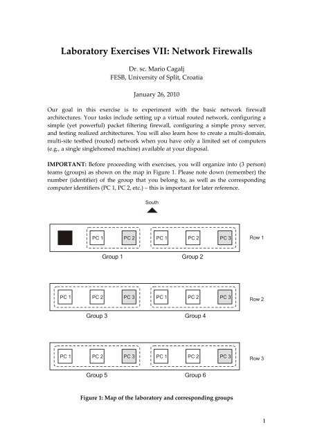
IMPORTANT: Before proceeding with exercises, you will organize into (3 person)<br />
teams (groups) as shown on the map in Figure 1. Please note down (remember) the<br />
number (identifier) of the group that you belong to, as well as the corresponding<br />
computer identifiers (PC 1, PC 2, etc.) – this is important for later reference.<br />
PC 1<br />
PC 1<br />
South<br />
PC 1 PC 2 PC 1 PC 2 PC 3<br />
Group 1 Group 2<br />
PC 2 PC 3 PC 1 PC 2 PC 3<br />
Group 3 Group 4<br />
PC 2 PC 3 PC 1 PC 2 PC 3<br />
Group 5 Group 6<br />
Figure 1: Map of the laboratory and corresponding groups<br />
Row 1<br />
Row 2<br />
Row 3<br />
1
Exercise 1<br />
Answer the following questions.<br />
1. We will be using ipfw network firewall. An ipfw ruleset includes a default<br />
rule which says: allow ip from any to any. Which one of the basic<br />
firewall design policies ipfw firewall implements?<br />
2. Contrast (compare) the default design policy of ipfw with other policies.<br />
3. What are basic types of firewalls? Briefly describe each type.<br />
4. Which of the following choices do not scale well:<br />
(a) stateful inspection (b) application gateway (c) packet filters ? Explain<br />
why?<br />
5. Circuit-level gateway operates (monitors) at the application layer? Correct or<br />
not?<br />
6. What is the basic security issue (problem) with the screening router<br />
architecture?<br />
7. In the screened host firewall architecture (slide 27), what is the role of the<br />
screening router?<br />
8. What is the advantage of the dual-home gateway architecture compared to<br />
the screened host architecture?<br />
Exercise 2<br />
In this exercise each group from Figure 1 will set up a routed network that consists of<br />
two subnetworks as shown in Figure 2 (the testbed network). Each different group i<br />
(i=1,2,…,6) should set the value of x in the corresponding IP addresses to i (e.g., for<br />
group 3, IP address 10.0.X.2 reads 10.0.3.2). Please note that the testbed network is a<br />
basis for all later (firewall related) exercises, and you should carefully test your setup<br />
(using ping and tracert commands) before moving on to next exercise.<br />
2
Station 1<br />
Router<br />
10.0.X.2 10.0.X.1 15.0.X.1<br />
10.0.X.0/24<br />
subnet<br />
15.0.X.2<br />
15.0.X.3<br />
15.0.X.0/24<br />
subnet<br />
Station 2<br />
Station 3<br />
Figure 2: Targeted testbed network (for Group X)<br />
The targeted testbed network can be summarized as follows:<br />
It has two subnetworks 10.0.X.0/24 and 15.0.X.0/24 joined by a router.<br />
The router a network interface 10.0.X.1 on one subnet and an interface<br />
15.0.X.1 on another.<br />
Subnet 10.0.X.0 (an external network) has one WinXP host on it with the IP<br />
address 10.0.X.2 .<br />
Subnet 15.0.X.0 (an internal network) has two WinXP hosts on it with the IP<br />
addresses 15.0.X.2 and 15.0.X.3 .<br />
Setting Up the Testbed <strong>Network</strong><br />
IMPORTANT: If you are not sure what you have to do at any of the following steps,<br />
please do contact the professor or the assistant.<br />
Task 2.1. Introduction – Virtual PCs and Emulated <strong>Network</strong> Adapters<br />
We can see from Figure 2 that the testbed network comprises four devices,<br />
while each group in Figure 1 has at most three PCs in it. Moreover, a router<br />
should be equipped with at least two network interfaces (adapters,<br />
controllers - NICs). How can we then realize the required tesbed network in<br />
this setting?<br />
Thanks to Microsoft Virtual PC, we can create and run one or more virtual<br />
machines, each with its own operating system (Windows, Unix), on a single<br />
computer. In addition, with Virtual PC we can specify and configure up to<br />
four emulated network adapters to be used for the virtual machine. Thus,<br />
using Virtual PC we can easily emulate all stations and routers (multihomed<br />
virtual PCs) required for our testbed network.<br />
In our exercises, computers with the identifier PC 3 (see Figure 1) will<br />
emulate Station 3 and the router in Figure 2. More precisely, the host<br />
operating system (OS) on the PC 3 will be configured as Station 3 and the<br />
virtual machine created on PC 3 will be configured as the router. Finally, PC 1<br />
3
and PC 2 will act as Station 1 and Station 2, respectively. This holds for all the<br />
groups except group 1 which has only 2 computers.<br />
GROUP 1 ONLY: PC 1 will act as Station 1, a virtual machine (installed on PC<br />
2) named Virtual PC 2 will act as a Station 2, another virtual machine on PC 2<br />
will be configured as the router (Router). Finally, the host operating system<br />
on the PC 2 will be configured as Station 3. In summary, physical PC 2 (in<br />
group 1) will host 2 virtual machines.<br />
Task 2.2. Setting Up the Router<br />
Recall from Task 2.1, the router in Figure 2 will be emulated using a virtual<br />
machine installed on the computer with identifier PC 3. To start the virtual<br />
machine Router, in the Start menu on PC 3 choose (“click”) Microsoft Virtual<br />
PC to open Virtual PC Console window as shown in Figure 3. Click Start<br />
button to start virtual machine Router.<br />
Figure 3: Virtual PC Console<br />
Configure (two virtual) network adapters using the addresses indicated in<br />
Figure 2. In other words, you have to configure the TCP/IP properties for<br />
each connection on Router virtual machine started in the previous step: Local<br />
Area Connection and Local Area Connection 2.<br />
Open Regedit.exe on Router virtual machine, navigate to<br />
HKEY_LOCAL_MACHINE\SYSTEM\CurrentControlSet\Services\Tcpip\Para<br />
meter<br />
and set the value of IPEnableRouter to 1. Restart the virtual machine<br />
Router for this changes to take effect. Do not restart the host machine PC 3.<br />
At this stage, you have turned your multi-homed virtual machine Router into<br />
a router.<br />
Task 2.3. Setting Up the Stations<br />
Configure network adapters (the TCP/IP properties for each connection) on<br />
physical computers PC 1 and PC 2 using the addresses indicated in Figure 2.<br />
4
Recall, PC 1 and PC 2 will act as Station 1 and Station 2, respectively. Finally,<br />
the host operating system on physical PC 3 will be configured as Station 3.<br />
GROUP 1 ONLY: Virtual PC 2 will be configured as Station 2. The host<br />
operating system on physical PC 2 will be configured as Station 3.<br />
Task 2.4. Testing your Setup<br />
Test your setup by using the ping command to ping any host (station) in one<br />
subnet from any host in the other subnet. Provide evidence that you have set<br />
up the required network topology (Figure 2) – use tracert command for<br />
this purpose. Make sure that you have turned off WinXP personal firewalls<br />
on all the machines (including virtual machines).<br />
Exercise 3<br />
The goal is to configure a packet filtering firewall ipfw (ip firewall), hosted by<br />
Router virtual machine, in such a way to block and/or allow certain type of traffic<br />
over the tesbed network. By installing a packet filter on the router, we have turned it<br />
into a screening router. Ipfw firewall supports both the command mode and the<br />
graphical mode of operation. Its use is self-explanatory, in particular in the graphical<br />
mode (see Figure 4). For detailed information you can consult README.TXT file<br />
accompanying ipfw installation in folder c:\ipfw.<br />
Figure 4: ipfw GUI<br />
In the graphical mode it is fairly easy to define different firewall rules. You start by<br />
clicking on the “New rule” button and the remaining steps are self-explanatory.<br />
Before defining and running your own rules for the first time, “flush” (remove) any<br />
existing rules. Observe in Figure 4 that it is possible to define and install multiple<br />
rules simultaneously (a ruleset). Also, observe that an ipfw ruleset always includes a<br />
5
default rule (numbered 65535) which cannot be modified or deleted, and matches all<br />
packets.<br />
Task 3.1. Starting the Firewall<br />
Browse to the folder c:\ipfw. Execute install.bat or install-deny.bat<br />
in order to install the firewall with “allow all” or “deny all” default policy,<br />
respectively. Use uninstall.bat to uninstall the firewall. Browse to the<br />
folder c:\wipfw and execute qtfw.exe to get a graphical view (Figure 4).<br />
Task 3.2. Implementing a Security Policy 1<br />
Station 1<br />
10.0.X.0/24<br />
subnet<br />
Router<br />
flow 1<br />
flow 2<br />
15.0.X.0/24<br />
subnet<br />
Figure 5: <strong>Network</strong> flows to block/allow<br />
Station 2<br />
Station 3<br />
Consider the flows shown in Figure 5. Your task is to define, install and test a<br />
firewall rulset that implements the following policies (provide some evidence<br />
that your ruleset indeed implements the policies – for example, you can use<br />
traces obtained from <strong>Network</strong> Monitor tool):<br />
1. Block ICMP flow 1 (ping) from Station 1 and allow ICMP flow<br />
from Station 2.<br />
2. Allow ICMP flow 2 (ping) from Station 1 and block ICMP flow<br />
2 from Station 3.<br />
3. Block both ICMP flow 1 and flow 2 from any IP address on the<br />
“external” network (10.0.X.0) and allow both ICMP flow 1 and flow 2<br />
originating from the “internal” network.<br />
Task 3.3. Implementing a Security Policy 2<br />
Station 3 hosts both a web server and an ftp server. Make sure that you can access<br />
them (e.g., ftp 15.0.X.3 and using a web browser try http://15.0.X.3). Your task is<br />
6
to define and install a firewall rulset that implements the following policies<br />
(provide some evidence that your ruleset indeed implements the policies):<br />
1. Allow access to the web server and block access to the ftp server from<br />
Station 1.<br />
2. Block access to the web server and allow access to the ftp server from<br />
any computer on the “external” network.<br />
Task 3.4. Answer the Following Questions<br />
1. Assume that Station 2 in Figure 5 represents a bastion host. How do we call<br />
the resulting firewall architecture (system)?<br />
2. Is it possible to define firewall rules on the router, in the configuration in<br />
Figure 5, such that we block all traffic between Station 2 and Station 3?<br />
Explain your answer.<br />
3. What is the problem with the first policy from Task 3.2 ? (Hint: Think how<br />
can a ping still reach Station 2 from the subnet 10.0.X.0 .)<br />
Exercise 4<br />
In this exercise your task is to implement the policy depicted in Figure 6: Station 1<br />
should only be able to access the web/ftp server via the application proxy (CCProxy)<br />
that is hosted by Station 2 – no direct connection between any “external” computer<br />
and the servers is allowed.<br />
Station 1<br />
10.0.X.0/24<br />
subnet<br />
Router<br />
15.0.X.0/24<br />
subnet<br />
Station 2<br />
Station 3<br />
Figure 6: <strong>Network</strong> flows to block/allow<br />
Proxy<br />
server<br />
WEB/FTP<br />
server<br />
In the first step you have to configure the proxy server hosted by Station 2. From the<br />
start menu start proxy server CCProxy (Figure 7). By clicking on Account button you<br />
will open Account Manager window. Account Manager allows you to configure the<br />
server proxy – to control the access to the proxy server based on the number of<br />
authentication methods (MAC, IP address, password based, different combinations).<br />
7
Account manager is fairly simple – it is self-explanatory (however, if you do not feel<br />
comfortable with it, please do contact the professor or the assistant).<br />
Figure 7: CCProxy GUI<br />
Please note that you will have to configure a web browser on Station 1 so that it uses<br />
Station 2 as a proxy server for accessing the web/ftp server. Your task is to define and<br />
install a firewall ruleset and configure the proxy server such that:<br />
1. Station 1 is denied a direct access to the web/ftp server.<br />
2. Only Station 1 is authorized to access the web/ftp server, but through the<br />
proxy server.<br />
Provide some evidence that your setup works properly (use <strong>Network</strong> Monitor). Also<br />
explain the following observation: Station 2 is not configured as a router. Still,<br />
Station 1 connects to the web/ftp server through Station 2. How does it work? (Hint:<br />
You may want to use <strong>Network</strong> Monitor at Station 2 and observe what happens<br />
during connection establishment.)<br />
8