
Create successful ePaper yourself
Turn your PDF publications into a flip-book with our unique Google optimized e-Paper software.
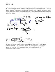
HW 5 S12 solns<br />
HW 3_F11<br />
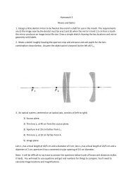
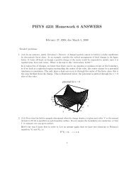
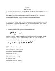
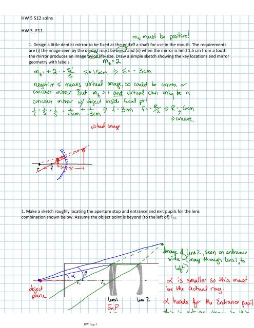
1. Design a little dentist mirror to be fixed at the end of a shaft for use in the mouth. The requirements<br />
are (i) the image seen by the dentist must be erect and (ii) when the mirror is held 1.5 cm from a tooth<br />
the mirror produces an image twice life-size. Draw a simple sketch showing the key locations and mirror<br />
geometry with labels.<br />
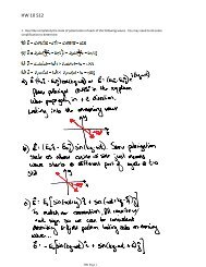
1. Make a sketch roughly locating the aperture stop and entrance and exit pupils for the lens<br />
combination shown below. Assume the object point is beyond (to the left of) Fo1.<br />
HW Page 1
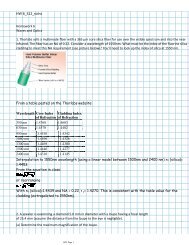
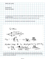
2. An optical system, centered on an optical axis, consists of (left to right)<br />
1) Source plane.<br />
2) Thin lens L1 at 40 cm from the source plane.<br />
3) Aperture A at 20 cm farther from L1.<br />
4) Thin lens L2 at 10 cm farther from A.<br />
5) Image plane.<br />
Lens L1 has a focal length of 40/3 cm and a diameter of 2 cm; lens L2 has a focal length of 20/3 cm and a<br />
diameter of 2 cm; aperture A has a centered circular opening of 0.5 cm diameter.<br />
Note: it will be difficult to ray trace to answer the questions below (scale of lenses and distances makes it<br />
hard). You will need to use equations and get real numbers for things to compare. You’ll need to calculate<br />
image locations and magnifications.<br />
(a) Sketch the system.<br />
(b) Find the location of the image plane (as a number).<br />
(c) Locate the aperture stop and entrance pupil (give specific info about location and size).<br />
(d) Locate the exit pupil (give specific info about location and size).<br />
HW Page 2
HW Page 3
HW Page 4
3. Consider the unaccommodated crystalline lens of the eye as an isolated unit having radii of curvature and a<br />
refractive index as given in Table 19-2 in your textbook (refer to figure 19.3).<br />
(a) Calculate its focal length as a thin lens in air.<br />
(b) Calculate its focal length as a thin lens in its actual environment (see figure 19.3)<br />
(c) Calculate where an incoming ray, parallel to the optical axis, will cross the optical axis. Report this distance<br />
from the back vertex of the lens. Treat the lens as a thick lens of thickness 3.6 mm, in its actual environment.<br />
Include the transmission of the ray through the cornea also (so the ray is parallel to the optical axis in air, before<br />
it hits the cornea).<br />
HW Page 5
(c) Need to use equations for single refracting surface, one at a time. The cornea first finding s1'), then<br />
the refraction at the first lens surface (finding s2'), the refraction at the second lens surface (finding s3').<br />
The final s3' will be the final image formation (with initial object at infinity in front of eye), as measured<br />
from the back vertex of the lens, which is the vertex of the third refracting surface in the calculation.<br />
Graduate Student Problem (PHYS 5271, MEGR 7090 and MEGR 8090)<br />
4. The figure below shows a lens system, an object, and the appropriate pupils. Sketch marginal rays and<br />
the chief ray to locate the image.<br />
HW Page 6
HW Page 7