8-/16-Port Essential Sentinel KVM User's Manual
8-/16-Port Essential Sentinel KVM User's Manual
8-/16-Port Essential Sentinel KVM User's Manual

You also want an ePaper? Increase the reach of your titles
YUMPU automatically turns print PDFs into web optimized ePapers that Google loves.
8-/<strong>16</strong>-<strong>Port</strong> <strong>Essential</strong><br />
<strong>Sentinel</strong> <strong>KVM</strong><br />
User’s <strong>Manual</strong><br />
Version 1.10
Index<br />
1. INTRODUCTION ........................................................................................................................................ 4<br />
2. SPECIFICATIONS ..................................................................................................................................... 5<br />
3. SYSTEM REQUIREMENTS ..................................................................................................................... 6<br />
4. INSTALLATION .......................................................................................................................................... 6<br />
4.1. FRONT VIEW ........................................................................................................................................ 6<br />
4.2. REAR VIEW .......................................................................................................................................... 7<br />
4.3. SINGLE STAGE INSTALLATION ............................................................................................................. 7<br />
4.3.1. Precaution: .............................................................................................................................. 7<br />
4.3.2. Console connection: ............................................................................................................ 7<br />
4.3.3. System connection: .............................................................................................................. 8<br />
4.4. CASCADE CHAINING ......................................................................................................................... 10<br />
4.5. RACK MOUNTING .............................................................................................................................. 13<br />
5. OPERATION ............................................................................................................................................. 13<br />
6. HOT KEY OPERATION .......................................................................................................................... 14<br />
6.1. CALL OSD MENU .............................................................................................................................. 14<br />
6.2. LEADING HOT KEY SELECT .............................................................................................................. 14<br />
6.3. CHANNEL SELECT - SINGLE <strong>KVM</strong> .................................................................................................... 14<br />
6.3.1. Specific channel selection ................................................................................................ 14<br />
6.3.2. Arrow Key Channel Shift Function ................................................................................. 15<br />
6.3.3. Channel Shift Function ......................................................................................... 15<br />
6.4. CHANNEL SELECT - CASCADE CHAIN LAYER .................................................................................. <strong>16</strong><br />
6.5. BUZZER SOUND DISABLE / ENABLE ................................................................................................. 17<br />
6.6. AUTO-SCAN FUNCTION ..................................................................................................................... 17<br />
6.6.1. Start auto-scan function .................................................................................................... 17<br />
6.6.2. Stop auto-scan function .................................................................................................... 18<br />
6.6.3. Auto-scan mode .................................................................................................................. 18<br />
6.6.4. Auto-scan time interval ..................................................................................................... 18<br />
6.7. CONSOLE LOCK ................................................................................................................................ 18<br />
7. OSD OPERATION ................................................................................................................................... 19<br />
7.1. OSD MAIN MENU .............................................................................................................................. 19<br />
7.1.1. <strong>KVM</strong> layer number ............................................................................................................... 19<br />
7.1.2. Channel name ...................................................................................................................... 19<br />
2
7.1.3. Computer & <strong>KVM</strong> status .................................................................................................... 20<br />
7.1.4. Current active channel number ....................................................................................... 20<br />
7.1.5. Cascade parent channel number .................................................................................... 20<br />
7.1.6. Page down / up indicator .................................................................................................. 20<br />
7.1.7. Function Control Menu ...................................................................................................... 21<br />
7.2. CHANNEL SELECTION IN OSD .......................................................................................................... 21<br />
7.2.1. Channel select to computer ............................................................................................. 21<br />
7.2.2. Channel select to cascade port ....................................................................................... 21<br />
7.2.3. Return from cascade port ................................................................................................. 22<br />
7.3. SETUP IN OSD: ....................................................................................................................... 22<br />
7.3.1. Scan Mode ............................................................................................................................ 22<br />
7.3.2. Scan Time .............................................................................................................................. 23<br />
7.3.3. Banner Time ......................................................................................................................... 23<br />
7.3.4. Position .................................................................................................................................. 23<br />
7.3.5. Hot key ................................................................................................................................... 23<br />
7.3.6. Sound ..................................................................................................................................... 24<br />
7.3.7. Language ............................................................................................................................... 24<br />
7.4. AUTO-SCAN IN OSD: .............................................................................................................. 24<br />
7.4.1. Start to auto-scan in OSD ................................................................................................. 24<br />
7.4.2. Stop auto-scan ..................................................................................................................... 24<br />
7.4.3. Auto-scan mode .................................................................................................................. 25<br />
7.4.4. Auto-scan time interval ..................................................................................................... 25<br />
7.5. CONSOLE LOCK IN OSD: ....................................................................................................... 25<br />
7.6. CHANNEL RENAME: ................................................................................................................. 26<br />
7.7. SECURITY SETUP: ................................................................................................................... 26<br />
7.7.1. Security mode login ........................................................................................................... 26<br />
7.7.2. Security Mode ...................................................................................................................... 27<br />
7.7.3. Change administrator password ..................................................................................... 27<br />
7.7.4. Authorized user setup ....................................................................................................... 28<br />
7.7.5. User Authority setup .......................................................................................................... 28<br />
7.8. LOCK PORT: ............................................................................................................................ 29<br />
7.8.1. Lock <strong>Port</strong> ............................................................................................................................... 29<br />
7.8.2. Channel selection of the locked port ............................................................................. 29<br />
7.8.3. Unlock <strong>Port</strong> ........................................................................................................................... 29<br />
7.9. EXIT OSD: ........................................................................................................................... 29<br />
8. SUN MICROSYSTEMS FUNCTION KEY EMULATION: .................................................................. 30<br />
9. TROUBLESHOOTING : .......................................................................................................................... 31<br />
3
1. Introduction<br />
Thank you for purchasing 8-port & <strong>16</strong>-port Combo Free <strong>KVM</strong> Switch! You<br />
now have a high quality, durable system to control 8 or <strong>16</strong> computers<br />
through PS/2 and/or USB connection from one console (PS/2 & USB Mouse,<br />
PS/2 & USB Keyboard, and Monitor).<br />
Features<br />
1. Console your Keyboard/Mouse via PS/2 and/or USB at will.<br />
2. Connect computers via PS/2 and/or USB at will.<br />
3. Supports Windows, Linux, Mac OS9/OSX, Sun Microsystems.<br />
4. On-Screen-Display (OSD) & Cascade Chain functions.<br />
5. OSD is intuitive menus driven for quick and efficient navigation.<br />
6. Supports Daisy chain with 3 level cascades: up to 3 levels; control up to<br />
64/256/4096 PCs, from a single console; cascaded units don’t need special<br />
configuration.<br />
7. Emulates PS/2 or USB keyboard on each PC to allow your computers to<br />
boot normally without a keyboard error.<br />
8. Supports hot-pluggable. All devices connected to the <strong>KVM</strong> can be added or<br />
removed at any time, without shutting the unit down.<br />
9. Supports 3 types of switching:<br />
- Hardware Push Button,<br />
- Hot-Keys on PS/2 and/or USB of keyboard,<br />
- Menu driven OSD (On Screen Display).<br />
10. Supports Auto-Scan function to switch video inputs automatically among<br />
computers in preset intervals sequentially by OSD menu driven.<br />
11. Supports LED display for PC and/or server status monitoring.<br />
12. Supports VGA resolutions up to 2048 x 1536<br />
13. Supports Beeper during Switching enabled.<br />
14. Fully compliant with the USB 1.1/ 2.0 specification.<br />
15. Rack Mountable in 19” system tack (1U).<br />
4
Package Contents<br />
The product you purchased should contain the following equipment and<br />
accessories:<br />
1 x 8-<strong>Port</strong> or <strong>16</strong>-<strong>Port</strong> Combo Free <strong>KVM</strong> Switch .<br />
1 x User’s <strong>Manual</strong>.<br />
1 x Power adaptor<br />
1 x Rack Mount Kit<br />
2 x Custom combo 4-in-1 cable<br />
2. Specifications<br />
Specification<br />
Number Of Computers Controlled 8 or <strong>16</strong><br />
Selection Method<br />
Push Button and Hot-Key (PS/2 / USB Keyboard)<br />
Or On-Screen-Display (OSD)<br />
LEDs<br />
Red for PC Selection<br />
Green for PC On-Line ready<br />
Video<br />
PC Connectors<br />
(KB/MS)<br />
8 / <strong>16</strong> x HDB-15 female<br />
( PS/2 & USB signal combined )<br />
Keyboard 1 x 6 pin mini-DIN female<br />
Mouse 1 x 6 pin mini-DIN female<br />
Console <strong>Port</strong>s Video 1 x HDB-15 female<br />
Keyboard 1 x USB – A type female<br />
Mouse 1 x USB – A type female<br />
Auto-Scan Interval Adjustable time setting by OSD menu driven<br />
DDC, DDC2 monitor Yes (Max. Resolution up to 2048 x1536)<br />
Hot Swappable Yes<br />
Operating systems supported<br />
Windows 98SE/ME/2000/XP/Vista/7/2003 Server,<br />
Linux, Mac OS9/OSX and Sun Microsystems.<br />
Power By external power adaptor<br />
Dimensions (L X W X H) 44 x 15.7 x 4.5 cm (17.3 x 6.1 x 1.5 inch )<br />
Unit Weight 1750g / 1900 g<br />
Housing material Metal<br />
Operating Temperature 32~ 122°F (0~ 50°C )<br />
Humidity 0%~80%RH<br />
5
3. System Requirements<br />
Console<br />
A VGA, SVGA, Multisync monitor capable of the highest resolution.<br />
PS/2 and/or USB Keyboard/Mouse<br />
Computer or Server<br />
The following equipment must be equipped with each computer or server.<br />
A VGA, SVGA or Multisync card<br />
Type A USB port or PS/2 6 pin mini-DIN for Keyboard and Mouse.<br />
Cables<br />
The Combo Free <strong>KVM</strong> Switch must be used specific custom 4-in-1 cables.<br />
To purchase the specific cable sets, please contact your dealer.<br />
4. Installation<br />
4.1. Front View<br />
8-<strong>Port</strong><br />
<strong>16</strong>-<strong>Port</strong><br />
LED Indicators:<br />
Selected:<br />
Figure 1: 8-port <strong>KVM</strong> front view<br />
Figure 2: <strong>16</strong>-port <strong>KVM</strong> front view<br />
RED LED indicates that the <strong>KVM</strong> Switch is selected to the corresponding PC.<br />
On-Line:<br />
GREEN LED indicates that the <strong>KVM</strong> Switch is ready to the corresponding PC.<br />
6
Reset Switch :<br />
Press Reset switch when you want to reset the system. This switch must be<br />
pushed with a thin object like the end of a paper clip, or a ball point pen.<br />
4.2. Rear View<br />
8-<strong>Port</strong><br />
<strong>16</strong>-<strong>Port</strong><br />
4.3. Single stage installation<br />
Figure 3: 8-port <strong>KVM</strong> read view<br />
Figure 4: <strong>16</strong>-port <strong>KVM</strong> read view<br />
4.3.1. Precaution:<br />
Please turn off computers and devices when you start to install <strong>KVM</strong><br />
Switch.<br />
For computers with Keyboard Power On function, please unplug the power<br />
cords in advance. Otherwise, the switch might not work properly.<br />
If your computeres work under Windows 98, please connect <strong>KVM</strong> switch<br />
to computers via PS/2 ports, because Windows 98 does not support<br />
installation at first time as through USB HID installation driver.<br />
Some old computers must enable USB setting in BIOS in advance to<br />
make USB interface work.<br />
This <strong>KVM</strong> switch does not guarantee to fully support USB keyboard with<br />
USB HUB.<br />
4.3.2. Console connection:<br />
Plug keyboard, mouse and monitor to the console ports on the real panel<br />
of <strong>KVM</strong> Switch. (Figure 5)<br />
7
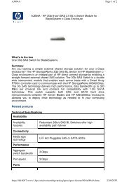
4.3.3. System connection:<br />
Fig. 1<br />
Figure 5: Console connection<br />
Please use Custom combo cable to connect your computers.<br />
Please refer to the figures and instruction shown below for System<br />
connection.<br />
Note: Please contact your dealer to purchase the custom combo 4-1<br />
cables if you need.<br />
Figure 6: Custom combo 4-in-1 cable<br />
8
You can connect <strong>KVM</strong> switch to computers via three methods shown<br />
below:<br />
A. Connect USB, PS/2 (keyboard/mouse) and VGA connectors to<br />
computers. We recommand users to connect computers in this way.<br />
(Figure 7)<br />
Figure 7: USB & PS/2 (Keyboard & Mouse) and VGA connected<br />
B. Connect only PS/2 (keyboard/mouse) and VGA connectors to<br />
computers (Figure 8).<br />
Figure 8: PS/2 (Keyboard & Mouse) and VGA connected<br />
9
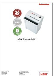
C. Connect only USB and VGA connectors to computers. (Figure 9).<br />
4.4. Cascade Chaining<br />
Figure 9: USB and VGA video connected<br />
Combo Free 8-port & <strong>16</strong>-port <strong>KVM</strong> switch support 3 level cascades; control<br />
up to 64/256/4096 PCs, from a single console; cascaded units don’t need<br />
special configuration. Cascade configuration expands system ability and<br />
allows you to select computers connected to the Master or Slave. After<br />
connected, <strong>KVM</strong> Switches automatically configure Master and Slave.<br />
To Install cascade chain, please follow the instruction below:<br />
A. Please turn off computers and devices when you start to install <strong>KVM</strong><br />
Switch.<br />
B. Use the custom combo cable set (See Figure 6), to connect one or more<br />
Slave <strong>KVM</strong> Switches to any PC port of Master <strong>KVM</strong> Switch. The<br />
connection between <strong>KVM</strong> to <strong>KVM</strong> must be connected through PS/2<br />
connection. ( Please refer to Figure 7 & Figure 8 ).<br />
C. You can do console Master <strong>KVM</strong> Switch via either USB and/or PS/2<br />
keyboard and mouse at will.<br />
D. Plug in the power adapter of the first level Master <strong>KVM</strong> Switch and<br />
connect Master <strong>KVM</strong> switch to computers.<br />
10
E. Next, plug in power adapter for each level Slave <strong>KVM</strong> Switch and connect<br />
Slave <strong>KVM</strong> switch to computers .<br />
F. The power on sequence should be:<br />
1. Master <strong>KVM</strong> Switch<br />
2. Second level Slave <strong>KVM</strong> Switch (connecting to Master <strong>KVM</strong> Switch) if<br />
any.<br />
3. Third level Slave <strong>KVM</strong> Switch (connecting to second level Slave <strong>KVM</strong><br />
Switch) if any.<br />
4. All computers connecting to Master/Slave <strong>KVM</strong> Switch.<br />
G. After all <strong>KVM</strong> Switches are powerd by power adaptor, trun on the<br />
computers.<br />
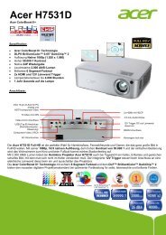
Initial Plug-in Process:<br />
Please plug in the Master <strong>KVM</strong> Switch first before turning on any<br />
other devices like montior or computers.<br />
Hot plug and Hot Swap:<br />
Combo Free 8-port & <strong>16</strong>-port <strong>KVM</strong> switch support Hot plug and Hot swap<br />
function.<br />
11
Figure 10: Cascade chaining<br />
12
4.5. Rack Mounting<br />
Figure 11: Rack mounting<br />
Figure 11 shows you how to attach mounting brackets to the <strong>KVM</strong> Switch unit<br />
for standard 19-inch rack cabinet.<br />
5. Operation<br />
1. Screw the mounting brackets into the sides of the <strong>KVM</strong> Switch unit.<br />
( See Figure 11)<br />
2. Install the <strong>KVM</strong> Switch unit into the rack cabinet.<br />
You can control computers via 8-<strong>Port</strong> or <strong>16</strong>-<strong>Port</strong> Combo Free <strong>KVM</strong> Switch by<br />
push button, hot key and OSD.<br />
1. Push button operation<br />
Press the front panel push button to select the PC and operate it.<br />
2. Hot Key operation<br />
Please refer section 6. Hot Key Operation.<br />
3. OSD operation<br />
Please refer section 7. OSD Operation.<br />
13
6. Hot Key Operation<br />
6.1. Call OSD Menu<br />
Press < Scroll Lock> twice and , then the OSD “Main Menu” will be<br />
displayed on the monitor screen. All of the <strong>KVM</strong> parameters can be setup in<br />
OSD mode. You can also execute some <strong>KVM</strong> functions in OSD.<br />
→ → <br />
6.2. Leading Hot Key Select<br />
The two-steps hot key sequence is used for quick function execution.<br />
The leading key is by default. However, you can change the<br />
leading hot key if you want.<br />
By pressing twice, , then press , you can<br />
change the leading hot key.<br />
The available leading hot key are , < Num Lock > or < Caps<br />
Lock > for option.<br />
Setup leading hot key to < Scroll Lock ><br />
< CTRL > → < CTRL > → < Scroll Lock > → < Enter ><br />
Setup leading hot key to < Num Lock><br />
< CTRL > → < CTRL > → < Num Lock > → < Enter ><br />
Setup leading hot key to < Caps Lock ><br />
< CTRL > → < CTRL > → < Caps Lock > → < Enter ><br />
Note: You can also change leading hot key by pressing in OSD main<br />
menu. Please refer section 7.3.5 Setup in OSD – Hot Key.<br />
6.3. Channel Select - Single <strong>KVM</strong><br />
6.3.1. Specific channel selection<br />
You can select the connected computers by using the two-step Hot Key<br />
sequence. Press key twice (Step 1), then press key (1 to<br />
<strong>16</strong>) and (step 2) to select the computer you want to control.<br />
14
Figure 12: Specific channel selection hot key<br />
→ → → or<br />
→ → → or<br />
…<br />
…<br />
→ → → <br />
Note: You can also select computers in OSD menu. Move the indicator bar<br />
to the chanel to switch by using , or , then press to select the connected computer.<br />
Please refer section 7.2 Channel Selection in OSD.<br />
6.3.2. Arrow Key Channel Shift Function<br />
Press twice, and press or <br />
key to shift left/right one channel.<br />
Switch to left one channel<br />
→ → <br />
Switch to right one channel<br />
→ → <br />
6.3.3. Channel Shift Function<br />
1. Start Channel shift Function<br />
< ALT > channel shift function default was off. You can press Hot-Key<br />
twice, and then press to turn on or turn off<br />
this function alternately.<br />
2. Shift the channel by key<br />
Press left < ALT > or right < ALT > key twice, the PC channel will<br />
15
automatically shift to left or right one channel (channel decrease / increase<br />
to next) when < ALT > channel shift function is enabled.<br />
Enable/Disable channel shift function<br />
→ → < ALT > → <br />
Switch to left one channel<br />
→ < Left ALT ><br />
Switch to right one channel<br />
→ < Right ALT ><br />
6.4. Channel Select - Cascade Chain Layer<br />
You can select the active channel directly under cascade chain connection.<br />
The following hot key sequence is used for quick channel selection.<br />
Press twice, , the cascade channel number (1, 2, 3……<strong>16</strong>),<br />
and Press .<br />
Channel select to first layer<br />
< Scroll Lock > → < Scroll Lock > → → < CH-L1 > → < Enter ><br />
Channel select to second layer<br />
< Scroll Lock > → < Scroll Lock > → → < CH- L1 ><br />
<strong>16</strong><br />
→ → < CH-L2 > → < Enter ><br />
Channel select to third layer<br />
< Scroll Lock > → < Scroll Lock > → → <br />
→ → < CH-L2 ><br />
→ → < CH-L3 > → < Enter ><br />
Note: With cascading 3 layers, you can select last layer directly;<br />
Example: press twice, then D2D5D7, and :<br />
D2 : layer 1 channel 2 links to<br />
D5 : layer 2 channel 5 links to<br />
D7 : layer 3 channel 7 selected<br />
Note: You can also select active channel of cascade chain in OSD menu.<br />
Move the indicator bar to the chanel to switch by using ,
or , and then press to switch to the<br />
target port. Please refer section 7.2.2 Channel select to cascade port.<br />
6.5. Buzzer sound Disable / Enable<br />
Press twice, then and . The buzzer sound will be<br />
disabled / enabled alternately. The buzzer sound default setting is ON.<br />
→ → → <br />
Note: You can also enable/disable buzzer sound by pressing in OSD<br />
main menu. Please refer section 7.3.6 Setup in OSD - Sound.<br />
Figure 13: Buzzer setup hot key<br />
6.6. Auto-Scan Function<br />
When you enable Auto-Scan function by pressing twice, then<br />
and . The <strong>KVM</strong> Switch will shift through all the ports and display<br />
them on the monitor.<br />
The mouse and keyboard will be disabled under this mode. This is necessary to<br />
prevent errors such as erratic movement and wrong characters to display when<br />
using the mouse or keyboard in accident.<br />
6.6.1. Start auto-scan function<br />
→ → → . The auto-scan<br />
banner will be shown to indicate the scanning channel.<br />
17<br />
.
Figure 14: Auto-scan hot key<br />
─┬── ┬ ──┬──────<br />
│ │ └─ Channel Name<br />
│ └────────── Channel Number<br />
└─────────────── Indicate now is Scan Mode<br />
Figure 15: Auto-scan Banner<br />
6.6.2. Stop auto-scan function<br />
Press any key on keyboard to STOP the auto-scan function. Press the push<br />
button on <strong>KVM</strong> front panel to select active port can stop the auto-scan<br />
function too.<br />
6.6.3. Auto-scan mode<br />
There are two auto-scan modes, please refer section 7.3.1 Setup in OSD –<br />
Scan Mode to setup the auto-scan mode.<br />
Scan all working computers.<br />
Scan all computers which are marked for auto-scan.<br />
6.6.4. Auto-scan time interval<br />
The auto-scan time interval can be adjustable by pressing in OSD<br />
main menu. Please refer section 7.3.1 Setup in OSD – Scan Time.<br />
Note: You can also start auto-scan function by pressing in OSD main<br />
menu. Please refer section 7.4 Auto-Scan in OSD.<br />
6.7. Console Lock<br />
If the security mode is enabled in OSD mode (by pressing in OSD mode),<br />
18
you can lock console by pressing twice, and then and<br />
. The <strong>KVM</strong> will be locked until an authorized user login.<br />
→ → → <br />
To unlock console, please press any key according to screen message, then key<br />
in User Name and Password. The <strong>KVM</strong> switch and console devices will be<br />
unlocked and back to normal status.<br />
Note: You can also execute console lock function by pressing in OSD<br />
main menu. Please refer section 7.5 Console Lock in OSD.<br />
7. OSD Operation<br />
7.1. OSD Main Menu<br />
Press < Scroll Lock> twice and , then you will enter to OSD (On<br />
Screen Display) main menu. The channel number, names and the status will be<br />
displayed on the monitor screen. Please refer fig. 8<br />
Fig. <strong>16</strong>: OSD main menu<br />
7.1.1. <strong>KVM</strong> layer number<br />
1 st , 2 nd or 3 rd . indicates the<br />
s<br />
current cascade level.<br />
s<br />
7.1.2. Channel name<br />
The channel name can be defined by using function key F4, it can remind<br />
user which computer is connected to this channel.<br />
A highlighted pink bar is shown in the selected channel row.<br />
19
A plus mark (+) showing in the left of channel name indicates that the port<br />
has cascades.<br />
7.1.3. Computer & <strong>KVM</strong> status<br />
<strong>KVM</strong> buzzer stauts<br />
Buzzer sound on<br />
Buzzer sound off<br />
Logined user name<br />
The system has one administrator and 3 users for security management.<br />
The name of current logined is displayed here.<br />
Channel LOCK indicator ( Status STA )<br />
L: Indicating this channel is locked.<br />
BLANK: Indicating this channel is normal without locked.<br />
Computer power on indicator ( Status STA ), OSD menu will update<br />
the flag automatically if the computer status is changed<br />
A: Indicating this computer is powered on and ready to select.<br />
BLANK: Indicating this computer is not connected or powered on.<br />
Channel scan indicator ( Status STA )<br />
S: This channel is marked for auto-scan if the scan mode is Select type.<br />
BLANK: Indicating this computer is not marked for auto-scan.<br />
7.1.4. Current active channel number<br />
Indicate current active channel number. The channel of the currently<br />
selected computer is displayed in the right-upper corner.<br />
If the active channel is in 2nd or 3rd cascade layer, the display string is like<br />
XX-YY-ZZ. For example, 02-05-07 means the active channel is layer 1<br />
channel 2 links to layer 2 channel 5, and layer 3 channel 7 is selected as<br />
active channel.<br />
7.1.5. Cascade parent channel number<br />
Indicate the parent channel of this cascade layer. The number at the<br />
left-upper corner below <strong>KVM</strong> layer number shows the number of port for<br />
the upper layer, i.e. 8 means link from channel 8 of upper <strong>KVM</strong>.<br />
It’s valid only for 2nd and 3rd cascade layer. It will show blank for 1st layer<br />
since there is no parent channel.<br />
7.1.6. Page down / up indicator<br />
This is for <strong>16</strong>-port <strong>KVM</strong> only. The information of port 1 ~ 8 are display in<br />
20
the first page, and information of port 9 ~ <strong>16</strong> are display in the second<br />
page. Since the port information is divide to two pages, the page down /<br />
up indicator can remind you to switch to alternative page by using and key.<br />
7.1.7. Function Control Menu<br />
The detail of control functions will be described in later sections. The list of<br />
control functions:<br />
F1: Set up: basic set up menu<br />
F2: Scan: autoscan function<br />
F3: Lock: setup lock/unlock, only available when F5 Security is enabled.<br />
F4: Rename: rename selected channel name.<br />
F5: Security: security function and user authority settings<br />
F6: Lock <strong>Port</strong>: PC port lock function (for administrator only)<br />
7.2. Channel selection in OSD<br />
7.2.1. Channel select to computer<br />
Use the and arrow keys to highlight a computer and then<br />
to select it and leave OSD menu. A banner with the channel<br />
name will be shown on left-upper corner of the screen.<br />
┬ ────┬──────<br />
│ └ Channel Name<br />
└──────────── Channel Number<br />
Fig. 17: Channel Banner (Single Layer)<br />
7.2.2. Channel select to cascade port<br />
A plus mark (+) showing in the left of channel name indicates that the port<br />
is under cascade channing. s Pressing in this channel will enter<br />
one level down, and the screen s<br />
pops up the listing of the computers of the<br />
slave <strong>KVM</strong>.<br />
21
┬ ┬ ┬ ────┬──────<br />
│ │ │ └ Channel Name<br />
│ │ └─────── Channel Number<br />
│ └────────── 2 nd Layer Channel Number<br />
└────────────── 1 st Layer Channel Number<br />
Fig. 18: Channel Banner (Cascade Layer)<br />
7.2.3. Return from cascade port<br />
After entering cascade port, press will return to upper layer OSD<br />
menu.<br />
s<br />
s<br />
7.3. Setup in OSD: <br />
Please use or arrow key to select the item you want to<br />
change, and use or arrow key to change the settings.<br />
Press to exit and save the setup settings.<br />
Figure 19: OSD Setup<br />
7.3.1. Scan Mode<br />
Select:<br />
Scan the selected channels marked with S in STA column on OSD main<br />
menu.<br />
PC ON:<br />
Scan all powered on PC channels<br />
22
7.3.2. Scan Time<br />
The default scan time is 5 seconds. It can be changed up to 90 seconds<br />
by stepping 5 seconds.<br />
7.3.3. Banner Time<br />
The default banner time is 5 seconds. It can be changed to 10 seconds, 15<br />
seconds, or always on (∞).<br />
7.3.4. Position<br />
Menu:<br />
Use four arrow keys to move the OSD main menu to the desired position.<br />
Press to save the changed menu position.<br />
Figure 20: Menu Position Setup<br />
Banner:<br />
Use four arrow keys to move the channel banner to the desired position.<br />
Press to save the changed banner position.<br />
Figure 21: Banner Position Setup<br />
7.3.5. Hot key<br />
Scroll Lock: becomes the hot key.<br />
Num Lock: becomes the hot key.<br />
Cap Lock: becomes the hot key.<br />
23
Note: You can also change leading hot key via hot key by using < CTRL > →<br />
< CTRL > → < New Hotkey > → < Enter > outside the OSD mode.<br />
Please refer section 6.2 Leading Hot Key Select.<br />
7.3.6. Sound<br />
ON: Buzzer sound enabled.<br />
OFF: Buzzer sound disabled.<br />
Note: You can also enable/disable buzzer sound via hot key by using<br />
→ → → outside the<br />
OSD mode. Please refer section 6.5 Buzzer sound Disable / Enable.<br />
7.3.7. Language<br />
English (En) / Deutsch (De) / Francais (Fr), 3 languages are available.<br />
7.4. Auto-Scan in OSD: <br />
7.4.1. Start to auto-scan in OSD<br />
Press in OSD main menu. The auto-scan banner will be shown to<br />
indicate the scanning channel.<br />
─┬── ┬ ──┬──────<br />
│ │ └─ Channel Name<br />
│ └────────── Channel Number<br />
└─────────────── Indicate now is Scan Mode<br />
Figure 22: Auto-Scan Banner<br />
Note: You can also start auto-scan function via hot key by using<br />
→ → → outside the<br />
OSD mode. Please refer section 6.6.1 Start Auto-Scan Function.<br />
7.4.2. Stop auto-scan<br />
Press any key on keyboard to STOP the auto-scan function. The<br />
auto-scan banner will disappear when the scan stops.<br />
24
7.4.3. Auto-scan mode<br />
There are two auto-scan modes, please refer section 7.3.1 Setup in<br />
OSD – Scan Mode to set up the auto-scan mode.<br />
Scan all computers which are power on.<br />
Scan all computers which are marked for auto-scan.<br />
7.4.4. Auto-scan time interval<br />
The auto-scan time interval of each port displayed can be adjustable by<br />
pressing in OSD main menu. Please refer section 7.3.2 Setup in<br />
OSD – Scan Time.<br />
7.5. Console Lock in OSD: <br />
If the security mode is enabled in OSD mode (by pressing in OSD mode,<br />
please refer section 7.7 Security Setup in OSD). You can logout to lock<br />
console by pressing In OSD mode. The Console Lock Banner will be<br />
shown on the screen.<br />
Figure 23: Console Lock Banner<br />
The <strong>KVM</strong> will be locked until an authorized user login.<br />
Figure 24: Unlock window<br />
Note: You can also logout to lock console via hot key by using<br />
→ → → outside the<br />
OSD mode. Please refer section 6.7 Console Lock.<br />
Note: If you forget the password, the only way to permanently<br />
disable the security function is to key in a universal password to<br />
unlock <strong>KVM</strong>. You need to key in this unlock password to release<br />
your device and <strong>KVM</strong>, and then you can restart everything. Please<br />
contact with your agency/distributor to get the universal password.<br />
25
7.6. Channel rename: <br />
Select the channel to rename by using up/down arrow key and press in<br />
OSD main menu. The channel rename window will be shown for setting up<br />
the channel name. Press to save the renamed channel name or<br />
to cancel.<br />
7.7. Security Setup: <br />
Figure 25: Channel Rename window<br />
7.7.1. Security mode login<br />
Press in OSD main menu to enter security setup mode, the<br />
administrator login is required before entering into the security mode.<br />
Figure 26: Security mode login window<br />
The default administrator account is:<br />
User Name: admin<br />
Password: 123456<br />
After login, the security setup main window will be shown on the screen.<br />
Please select the security item to setup via and key, and press or key to change the<br />
settings.<br />
26
Figure 27: Security setup main window<br />
7.7.2. Security Mode<br />
To change the security mode setting, please move the highlight bar to<br />
Security Mode, and press or key to change it.<br />
The Console Lock, <strong>Port</strong> Lock and user authority functions<br />
can not be executed until the security mode is enabled.<br />
7.7.3. Change administrator password<br />
To change the administrator password, move the highlight bar to<br />
Admin/password, and press or key. The<br />
administrator password setup window will be shown on the screen. Input<br />
the new password twice and press to confirm, or press <br />
to exit.<br />
Figure 28: Administrator password setup window<br />
27
7.7.4. Authorized user setup<br />
3 authorized users are admitted to manage the <strong>KVM</strong> switch. To change the<br />
user name and password, please move the highlight bar to the user for<br />
editing. Press or key, the user name and<br />
password setup window will be shown on the screen. Please Input the new<br />
user’s name and password twice, then press to confirm or<br />
to cancel.<br />
Figure 29: User name password setup window<br />
7.7.5. User Authority setup<br />
You can setup the authority for each user. Different user has different<br />
access right for each channel. To change the access right of each channel<br />
for certain user, please move the highlight bar to the channel, and press<br />
, , or to setup the channel access right for all or certain<br />
user. You don’t have to setup the authority of administrator since the<br />
administrator has all channel access right.<br />
Figure 30: User authority setup window<br />
28
7.8. Lock <strong>Port</strong>: <br />
7.8.1. Lock <strong>Port</strong><br />
Only administrator can lock port. Please move the highlight bar to the<br />
channel to lock, and press to lock the selected channel. A red L mark<br />
will be shown in STA column of locked port.<br />
Figure 31: Lock port in OSD main window<br />
7.8.2. Channel selection of the locked port<br />
If anyone selects the channel of the locked port either by panel<br />
push-button or hot key, the system will enter OSD mode waiting for<br />
administrator to unlock the port.<br />
7.8.3. Unlock <strong>Port</strong><br />
Only administrator login with correct password can unlock the port. After<br />
the administrator login, the red L mark in STA column will disappear.<br />
7.9. Exit OSD: <br />
Press to exit OSD and to return to the selected computer. A banner<br />
with the channel name will be shown on left-upper corner of the screen.<br />
29
8. Sun Microsystems Function Key Emulation:<br />
There are <strong>16</strong> special functions on the Sun Microsystems keyboard, Combo Free<br />
<strong>KVM</strong> Switch can emulate these function keys via PS/2 and/or USB keyboard.<br />
Please refer to the table shown below for Sun Microsystems keyboard special<br />
functions operation.<br />
To active these emulation on the PS/2 and/or USB keyboard, you have to press<br />
the key first (this key usually is located between the and ). Then press the second key ( Sun Microsystems<br />
Function Key ) . Please do not release when you press the<br />
second key.<br />
Sun Microsystems<br />
Function Key<br />
USB or PS/2 Keyboard<br />
Stop L_Win & L_Alt<br />
Props L_Win & L_Ctrl<br />
Compose L_Win & L_Shift<br />
Front L_Win & F1<br />
Open L_Win & F2<br />
Find L_Win & F3<br />
Again L_Win & F4<br />
Undo L_Win & F5<br />
Copy L_Win & F6<br />
Paste L_Win & F7<br />
Cut L_Win & F8<br />
Help L_Win & F11<br />
Power L_Win & F12<br />
Mute L_Win & 1<br />
Volume Down L_Win & 2<br />
Volume UP L_Win & 3<br />
30
9. Troubleshooting :<br />
Symptom Possible Cause Recommended Solution<br />
Keyboard and/or Mouse<br />
not working.<br />
Master/ Slave daisy<br />
chained doesn’t work<br />
Double OSD images at<br />
cascade configuration<br />
OSD menu is not at the<br />
proper position<br />
Keyboard and/or Mouse need<br />
to be reset<br />
Failed connection to the<br />
computer.<br />
<strong>KVM</strong> Switch needs to be reset<br />
Incorrect configuration or<br />
improper installation<br />
procedures<br />
Improper slave connection<br />
procedure.<br />
Fail connection<br />
OSD menu has fixed resolution<br />
and its size varies due to the<br />
changes of computer VGA<br />
resolution<br />
31<br />
To unplug from console<br />
port(s), and then replug<br />
it / them into console in.<br />
Check the cable connected<br />
from switch to computer and<br />
make sure it is connected<br />
properly.<br />
Power off all of devices and<br />
then power up again.<br />
Make sure the console of<br />
the Slave’s connected to<br />
Master’s PC port.<br />
Remove any possible power<br />
supplies to the slave<br />
( unplug all cables), before<br />
connecting it to the Master.<br />
Remove any possible power<br />
supplies to the Slave<br />
( unplug all cables), before<br />
connecting it to the Master.<br />
Make sure cable is<br />
connected well, Slave<br />
console link to Master port.<br />
Use : Set/Position to<br />
move OSD menu and<br />
banner to proper position.
Disclaimer<br />
Information in this document is subject to change without notice. The manufacturer does not make any representations or<br />
warranties (implied or otherwise) regarding the accuracy and completeness of this document and shall in no event be liable for<br />
any loss of profit or any other commercial damage, including but not limited to special, incidental, consequential, or other<br />
damages.<br />
No part of this document may be reproduced or transmitted in any form by any means, electronic or mechanical, including<br />
photocopying, recording or information recording and retrieval systems without the express written permission of the<br />
manufacturer.<br />
All brand names and product names used in this document are trademarks, or registered trademarks of their respective<br />
holders.<br />
FCC Statement<br />
This device generates and uses radio frequency and may cause interference to radio and television reception if not installed<br />
and used properly. This has been tested and found to comply with the limits of a Class B computing device in accordance with<br />
the specifications in Part 15 of the FCC Rules. These specifications are designed to provide reasonable protection against such<br />
interference in a residential installation. However, there is no guarantee that interference will not occur in a particular installation.<br />
If this device does cause harmful interference to radio or television reception, which can be determined by plugging the device<br />
in and out, the user can try to correct the interference by one or more of the following measures:<br />
Reorient or relocate the receiving antenna.<br />
Increase the separation between the device and receiver.<br />
Connect the computer into an outlet on a circuit different from that to which the receiver is connected.<br />
Consult the dealer or an experienced radio/TV technician for help.<br />
32