Copyright Technical Support - Chenbro
Copyright Technical Support - Chenbro
Copyright Technical Support - Chenbro

Create successful ePaper yourself
Turn your PDF publications into a flip-book with our unique Google optimized e-Paper software.
<strong>Copyright</strong><br />
http://www.chenbro.com<br />
1<br />
<strong>Chenbro</strong> 4-Port Multilane<br />
SATA Backplane User’s Manual<br />
This document is copyrighted, 2004, by <strong>Chenbro</strong> Micom Co., Ltd. All rights are reserved.<br />
<strong>Chenbro</strong> Micom Co., Ltd. reserves the right to make improvements to the products<br />
described in this manual at any time. Specifications are thus subject to change without<br />
prior notice.<br />
No part of this manual may be reproduced, copied, translated, or transmitted in any<br />
form or by any means without the prior written permission of <strong>Chenbro</strong> Micom Co., Ltd.<br />
Information provided in this manual is intended to be accurate and reliable. However,<br />
<strong>Chenbro</strong> Micom Co., Ltd., assumes no responsibility for its use, nor for any<br />
infringements upon the rights of third parties, which may result from its use.<br />
<strong>Technical</strong> <strong>Support</strong><br />
We want you to get the maximum performance from your products. So if you run into<br />
technical difficulties, we are here to help. For the most frequently asked questions, you<br />
can easily find answers in your product documentation. These answers are normally a<br />
lot more detailed than the ones we can give over the phone.<br />
So please consult this manual first. If you still cannot find the answer, gather all the<br />
information or questions that apply to your problem, and with the product close at hand,<br />
call your dealer. Our dealers are well trained and ready to give you the support you<br />
need to get the most from your <strong>Chenbro</strong> products. In fact, most problems reported are<br />
minor and are able to be easily solved over the phone.<br />
In addition, free technical support is available from <strong>Chenbro</strong> engineers every business<br />
day. We are always ready to give advice on application requirements or specific<br />
information on the installation and operation of any of our products.<br />
Preliminary Edition Printed in Taiwan Aug 2004
Hardware Specification<br />
Multilane SATA Backplane:<br />
http://www.chenbro.com<br />
2<br />
<strong>Chenbro</strong> 4-Port Multilane<br />
SATA Backplane User’s Manual<br />
An “Infiniband 4X receptacle” as host plug connector for 4 SATA channels.<br />
A power MOSFET to provide per disk power (5V and 12V) for each disk spin-up<br />
control.<br />
A uP to control the disk spin up function if LED board enable this function, set by a<br />
DIP switch pin, and start from the lowest position backplane. (i.e. the top one<br />
would be the latest to spin up.<br />
5 fan connectors (3 pins): each support 12V current up to 750mA (max power<br />
consumption: 9 watts)<br />
A 4x3 jumper with 4-digit jumper cap is added to select either disk power or disk<br />
activity for LED indication.<br />
A design hook with a zero ohm resistor to conduct disk reserved pin (P11) to<br />
disk activity LED. (It’s for the case that the pin is defined for disk LED output)<br />
Multiple SATA backplanes (up to 4) is cascaded by a connector to report fan, disk<br />
and thermal signals:<br />
1 thermal signal per SATA backplane reporting to LED module<br />
4 disk activity (or present) signals per SATA backplane reporting to LED<br />
module<br />
5 fan speed signals (for all SATA backplane) reporting to LED module<br />
A pre-charge circuit for surge current protection when a disk is plugged in.<br />
2 standard big-4P (Molex device connector) power inlets<br />
LED Module (for 2U/3U/4U)<br />
1 power button and 1 reset button<br />
1 buzzer for alerting and 1 alarm mute button (controlled by uP)<br />
2 standard USB 1.1/2.0 ports<br />
1 connector for RPS (Redundant Power Supply) fault event detection<br />
1 connector with signal controlled by uP to mute RPS built-in audio alarm<br />
1 connector with I 2 C signals as a design hook to support peripheral management<br />
interface<br />
1 connector to gather fan speed, disk activity, and thermal signals from SATA/SCSI<br />
backplane by a FFC cable<br />
Total 16 (4x4) LEDs for disk activity signal from 4 backplane<br />
4 thermal signal inputs from 4 backplane (detected by uP)<br />
Total 5 fans supported
http://www.chenbro.com<br />
3<br />
<strong>Chenbro</strong> 4-Port Multilane<br />
SATA Backplane User’s Manual<br />
5 mono LEDs: Power, LAN1, LAN2, HDD and Fan/Thermal event LEDs<br />
LED color: Power-Blue, LANs-Green, HDD-Amber, and Event-Red<br />
DIP switch to specify thermal warning level (55 or 65 degC)<br />
DIP switch to specify spin-up control for SATA backplane<br />
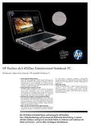
Backplane Layout<br />
Backplane Connectors<br />
CN4<br />
J1<br />
FAN5<br />
FAN4<br />
CN2<br />
CN3<br />
(Not Installed)<br />
FAN3<br />
JP1<br />
FAN2 FAN1 JP2<br />
SATA HDD1 SATA HDD2 SATA HDD3 SATA HDD4<br />
(1) [SATA_HDD1 / SATA_HDD2 / SATA_HDD3 / SATA_HDD4] : Connect SATA HDD<br />
(2) [JP1] : Connect next backplane LED connector<br />
(3) [CN4] : Connect Multilane SATA HBA<br />
(4) [FAN1 / FAN2 / FAN3 / FAN4 / FAN5] : Fan connectors<br />
(5) [CN1 / CN2] : Power connectors<br />
(6) [JP2] : Connect LED board or connect another backplane<br />
(7) [J1] : Choice present LED from HDD or SATA P11<br />
Pin Assignment<br />
[SATA_HDD1 / SATA_HDD2 / SATA_HDD3 / SATA_HDD4]<br />
Pin Def. Pin Def. Pin Def. Pin Def. Pin Def.<br />
S1 GND S6 B+ P1 N/C P6 GND P11 Reserved<br />
S2 A+ S7 GND P2 N/C P7 +5V P12 GND<br />
CN1<br />
SATA HDD Connector
S3 A- P3 N/C P8 +5V P13 +12V<br />
S4 GND P4 GND P9 +5V P14 +12V<br />
S5 B- P5 GND P10 GND P15 +12V<br />
[HDD1 / HDD2 / HDD3 / HDD4]<br />
Pin Def. Pin Def.<br />
S1 GND S5 B-<br />
S2 A+ S6 B+<br />
S3 A- S7 GND<br />
S4 GND<br />
[FAN1 / FAN2 / FAN3 / FAN4 / FAN5]<br />
Pin Def.<br />
1 GND<br />
2 +12V<br />
http://www.chenbro.com<br />
4<br />
<strong>Chenbro</strong> 4-Port Multilane<br />
SATA Backplane User’s Manual<br />
3 Sensor<br />
FAN Connector<br />
Note:<br />
(1) Please connect the chassis fan starting from FAN1<br />
(2) The fan MUST be connected with 4 or 5 fans due to chassis monitoring setting.<br />
[CN1 / CN2]<br />
Pin Def.<br />
1 +5V<br />
2 GND<br />
3 GND<br />
4 +12V<br />
[JP1] / [JP2]<br />
Pin Def. Pin Def. Pin Def.<br />
1 +5V 12 GND 23 HDD_LED_C#_2U<br />
2 +5V 13 Thermal_Sig_1U 24 HDD_LED_D#_2U<br />
3 +5V 14 Thermal_Sig_2U 25 HDD_LED_A#_3U<br />
4 GND 15 Thermal_Sig_3U 26 HDD_LED_B#_3U<br />
5 GND 16 Thermal_Sig_4U 27 HDD_LED_C#_3U<br />
6 GND 17 HDD_LED_A#_1U 28 HDD_LED_D#_3U<br />
7 Fan1_Sensor 18 HDD_LED_B#_1U 29 HDD_LED_A#_4U<br />
8 Fan2_Sensor 19 HDD_LED_C#_1U 30 HDD_LED_B#_4U<br />
HDD_HBA Connector<br />
Power Connector<br />
FFC Cable Connector
http://www.chenbro.com<br />
5<br />
<strong>Chenbro</strong> 4-Port Multilane<br />
SATA Backplane User’s Manual<br />
9 Fan3_Sensor 20 HDD_LED_D#_1U 31 HDD_LED_C#_4U<br />
10 Fan4_Sensor 21 HDD_LED_A#_2U 32 HDD_LED_D#_4U<br />
11 Fan5_Sensor 22 HDD_LED_B#_2U 33-34 Key-Pin<br />
Default Jumper Setting (with “*”)<br />
[J1]<br />
Pin Function<br />
1-2* Present Activity LED from HDD<br />
2-3 Present Activity LED from SATA Pin-11<br />
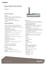
LED Module (for 2U/3U/4U) Layout<br />
LED Module Connectors<br />
J4<br />
Power LED (Blue)<br />
HDD LED (Orange)<br />
System Reset<br />
J1<br />
LED1 LED2 LED3 LED4<br />
[J1] : To USB Port of M/B<br />
Alarm Mute<br />
USB<br />
J2<br />
BZ1<br />
J3<br />
S1<br />
HDD Access LED Jumper<br />
Fan Fail LED (Red)<br />
J6<br />
J5<br />
LAN1 (Green)<br />
Power Switch<br />
LAN2 (Green)
[J2] : To M/B Control and LED Connector<br />
[J3] : Cascade to the top SATA/SCSI Backplane<br />
[J4] : I 2 C Management Connector (Reserved)<br />
[J5] : RPS (Redundant Power Supply) Fail Event Mute<br />
[J6] : PRS (Redundant Power Supply) Failure Alarm<br />
[S1] : Temperature Monitoring Configure Switch<br />
[BZ1] : Alarm Buzzer<br />
[USB] : 2 USB Ports<br />
[LED1 / LED2 / LED3 / LED4] : HDD LED Indicators<br />
Pin Assignment<br />
[J1]<br />
Pin Def. Pin Def.<br />
1 USB_Vcc 6 USB_Vcc<br />
2 USB_D0+ 7 USB_D1+<br />
3 USB_D0- 8 USB_D1-<br />
4 GND 9 GND<br />
5 Key-Pin 10 N/C<br />
[J2]<br />
Pin Def. Pin Def.<br />
1 Reset+ 7 HDD_LED+<br />
2 Reset_GND 8 HDD_LED-<br />
3 PS_ON 9 LAN1_LED+<br />
4 PS_ON_GND 10 LAN1_LED-<br />
5 Power_LED+ 11 LAN2_LED+<br />
6 Power_LED- 12 LAN2_LED-<br />
[J3]<br />
Pin Def. Pin Def. Pin Def.<br />
http://www.chenbro.com<br />
6<br />
<strong>Chenbro</strong> 4-Port Multilane<br />
SATA Backplane User’s Manual<br />
USB Connector<br />
System Control<br />
1 +5V 12 GND 23 HDD_LED_C#_2U<br />
2 +5V 13 Thermal_Sig_1U 24 HDD_LED_D#_2U<br />
3 +5V 14 Thermal_Sig_2U 25 HDD_LED_A#_3U<br />
4 GND 15 Thermal_Sig_3U 26 HDD_LED_B#_3U<br />
5 GND 16 Thermal_Sig_4U 27 HDD_LED_C#_3U<br />
6 GND 17 HDD_LED_A#_1U 28 HDD_LED_D#_3U<br />
7 Fan1_Sensor 18 HDD_LED_B#_1U 29 HDD_LED_A#_4U<br />
FFC Cable Connector
http://www.chenbro.com<br />
7<br />
<strong>Chenbro</strong> 4-Port Multilane<br />
SATA Backplane User’s Manual<br />
8 Fan2_Sensor 19 HDD_LED_C#_1U 30 HDD_LED_B#_4U<br />
9 Fan3_Sensor 20 HDD_LED_D#_1U 31 HDD_LED_C#_4U<br />
10 Fan4_Sensor 21 HDD_LED_A#_2U 32 HDD_LED_D#_4U<br />
11 Fan5_Sensor 22 HDD_LED_B#_2U 33-34 Key-Pin<br />
[J4]<br />
Pin Def.<br />
1 Data<br />
2 GND<br />
3 Clock<br />
4 Vcc<br />
[J5]<br />
Pin Def.<br />
1 TTL<br />
2 GND<br />
[J6]<br />
Pin Def.<br />
1 TTL<br />
2 GND<br />
Default Jumper Setting (with “*” )<br />
[S1]<br />
DIP Function ON OFF<br />
1 Monitoring BP Fan Q’ty Setting 4* 5<br />
2 Monitoring Temperature Setting 55 DegC* 65 DegC<br />
3 SATA HDD Spin Up Simultaneously<br />
ON<br />
Sequential<br />
Spin Up*<br />
I 2 C Connector<br />
RPS Fail Alarm<br />
RPS Fail Mute<br />
S1
Relative Parts<br />
http://www.chenbro.com<br />
8<br />
<strong>Chenbro</strong> 4-Port Multilane<br />
SATA Backplane User’s Manual<br />
(1) Multilane SATA cable: This cable is suggested to used with <strong>Chenbro</strong> Multilane SATA<br />
backplane due to the chassis mechanism design and limitation. And the cable<br />
length is 600mm (including connectors).<br />
(2) SATA HDD activity LED cable: This cable ONLY works with “3ware 9000 series SATA<br />
RAID card” which support dedicated connectors for activity LED signal output.<br />
<strong>Chenbro</strong> Multilane SATA and standard SATA backplane already reserved this feature<br />
to support and fulfill existing SATA storage chassis field monitoring for users.<br />
Figure-1: Multilane SATA cable & SATA HDD LED cable for activity<br />
Backplane Assembly<br />
The <strong>Chenbro</strong> 4-Port SATA Backplane can be assembly on <strong>Chenbro</strong> Storage Server<br />
Chassis (RM117 / RM215 / RM312 / RM414 / RM519), please refer to the Chassis<br />
Installation Guide for the necessary information.<br />
Note:<br />
(1) Backplane bracket is needed when doing assembly.<br />
(2) Backplane bracket and FFC cable are included in the Backplane Ass’y Kit.<br />
(3) When doing multiple backplane integration, the FFC cable must be installed on the<br />
backplane first. (See below for the details)
Figure-2: FFC connector on LED module<br />
Figure-3: Push the lever to lock FFC cable<br />
Figure-4: Folding the LED Board FFC cable<br />
http://www.chenbro.com<br />
9<br />
<strong>Chenbro</strong> 4-Port Multilane<br />
SATA Backplane User’s Manual<br />
FFC cable can be connected in<br />
on way only. The contact pin<br />
MUST face to “White” side of<br />
connector.
Backplane Wiring<br />
http://www.chenbro.com<br />
10<br />
<strong>Chenbro</strong> 4-Port Multilane<br />
SATA Backplane User’s Manual<br />
(1) Multilane SATA cable: The Multilane backplane is easy to connect to the 3ware<br />
Multilane SATA RAID card via just a single cable per backplane. However, due to the<br />
specific Multilane SATA connector is quite unique, user can refer to below figure for the<br />
cabling. Note only hearing “click” sound when plug in the connector is in well<br />
connection, otherwise it may lead to some system operation errors which caused by<br />
poor connection.<br />
Figure-5: Multilane SATA cable connection & real assembly in <strong>Chenbro</strong> RM414<br />
(2) SATA HDD activity LED cable (For “3ware 9000 series SATA RAID card):<br />
When hook up this cable please note one cable for only one backplane, user must have<br />
certain quantity of cable for the cabling. Please refer to below diagram for the wiring<br />
instruction:<br />
Figure-6: Backplane side connection
Figure-7: 3ware 9000 series SATA/RAID card connection<br />
http://www.chenbro.com<br />
11<br />
<strong>Chenbro</strong> 4-Port Multilane<br />
SATA Backplane User’s Manual<br />
Note:<br />
(a) Do NOT reverse the card side connector on cabling, otherwise the Chassis front<br />
LED will not work properly (see above picture).<br />
(b) Please refer to 3ware 9000 series SATA RAID card documentation for the relative<br />
connector definition.<br />
(3) Chassis assembly example: See below for the example of how the wiring to be<br />
performed.<br />
Example for 2U chassis Multilane SATA backplane wiring diagram (RM215):<br />
3ware SATA Chassis Fan x4<br />
RAID Card<br />
HDD5 HDD6 HDD7 HDD8<br />
HDD1 HDD2 HDD3 HDD4<br />
Multilane SATA cable (BP<br />
to Host Adaptor)<br />
LED FFC cable (BP to BP)<br />
Chassis fans wiring<br />
(Connection start from FAN1)
http://www.chenbro.com<br />
12<br />
<strong>Chenbro</strong> 4-Port Multilane<br />
SATA Backplane User’s Manual<br />
Example for 3U chassis Multilane SATA backplane wiring diagram (RM312):<br />
3ware SATA Chassis Fan x4<br />
RAID Card<br />
HDD9 HDD10 HDD11 HDD12<br />
HDD5 HDD6 HDD7 HDD8<br />
HDD1 HDD2 HDD3 HDD4<br />
Multilane SATA cable (BP<br />
to Host Adaptor)<br />
LED FFC cable (BP to BP)<br />
Chassis fans wiring<br />
(Connection start from FAN1)
http://www.chenbro.com<br />
13<br />
<strong>Chenbro</strong> 4-Port Multilane<br />
SATA Backplane User’s Manual<br />
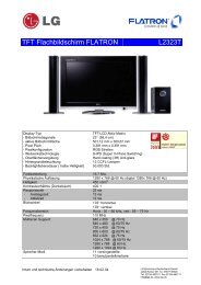
Example for 4U chassis Multilane SATA backplane wiring diagram (RM414):<br />
3ware SATA Chassis Fan x5<br />
RAID Card<br />
HDD13 HDD14 HDD15 HDD16<br />
HDD9 HDD10 HDD11 HDD12<br />
HDD5 HDD6 HDD7 HDD8<br />
HDD1 HDD2 HDD3 HDD4<br />
Chassis Compatibility<br />
The Multilane SATA backplane is particularly designed and used for 3ware 8000/9000<br />
series SATA RAID card, and <strong>Chenbro</strong> support this backplane and chassis based on<br />
specific models and revision. Please contact with your local sales and distributors for<br />
more details before you start to assembly. So far, <strong>Chenbro</strong> can support the chassis by:<br />
1U : RM117<br />
2U : RM215 (RM21502)<br />
3U : RM312 (RM31202)<br />
4U: RM414 (RM41402)<br />
5U: RM519 (RM51902)<br />
Multilane SATA cable (BP<br />
to Host Adaptor)<br />
LED FFC cable (BP to BP)<br />
Chassis fans wiring<br />
(Connection start from FAN1)
Note:<br />
http://www.chenbro.com<br />
14<br />
<strong>Chenbro</strong> 4-Port Multilane<br />
SATA Backplane User’s Manual<br />
The RM519 chassis support Multilane SATA backplane via another specific cable,<br />
please check with your sales or local distributors for more details.<br />
Any chassis in earlier version, users need to order the other relative parts, especially<br />
for 2U and 4U chassis. An additional “fan bar kit” and “LED board kit” will be needed for<br />
replacement. (See below parts list)<br />
Relative Part Number List<br />
Part No. Description Unit Remark<br />
26-143124-001 BP to LED Module FFC Cable, 280mm (for 1U) Pcs<br />
26-143215-002 BP to LED Module FFC Cable, 390mm (for 2U/3U/4U) Pcs<br />
26-143215-001 BP to BP (Cascade) FFC Cable, 110mm Pcs<br />
26-123215-001 Multilane SATA Cable, 600mm (1 pcs) Pcs<br />
26-113519-006 SATA HDD activity LED Cable, 700mm (1 pcs) Pcs<br />
26-033219-002 USB Cable 2.0, 750mm, Universal Specification Pcs<br />
26-033219-003 USB Cable 2.0, 600mm, Universal Specification Pcs<br />
80-103215-008 4-port Multilane SATA BP with Anti-static Bag Pcs<br />
84-321510-015 Ass’y 4-port Multilane SATA BP w/Bracket & screws<br />
(1 pcs, for RM215/312/414)<br />
84-311710-009 Ass’y 4-port Multilane SATA BP w/Bracket & screws<br />
(1 pcs, for RM117)<br />
84-312410-010 LED board kit, w/FFC cable (for RM117) Pack<br />
84-321510-016 LED board kit, w/FFC cable (for RM215/312/414) Pack<br />
84-321510-017 Fan bar kit (for RM21500/RM21501) Pack<br />
84-341410-005 Fan bar kit (for RM41400/RM41401) Pack<br />
Pcs<br />
Pcs