
You also want an ePaper? Increase the reach of your titles
YUMPU automatically turns print PDFs into web optimized ePapers that Google loves.
<strong>TechStyle</strong> <strong>System</strong>: The Management and Memory of<br />
Electronic Fabric Input and Output<br />
<strong>MIT</strong> Undergraduate Thesis<br />
Abraham Hsu (madentai@mit.edu)<br />
Lab: <strong>MIT</strong> <strong>Media</strong>, Arts, Sciences, <strong>Media</strong> Laboratory<br />
20 Ames Street<br />
Cambridge, MA 02139<br />
In collaboration with Collins & Aikman<br />
Group: <strong>Media</strong> <strong>Fabrics</strong> Group, <strong>TechStyle</strong><br />
Supervisors: Glorianna Davenport (gid@media.mit.edu)<br />
Hyun-Yeul Lee (hyun@media.mit.edu)<br />
Alumni Contributors: Alex Crumlin and Charles Hightower<br />
Date: May 10 th , 2004<br />
Abstract<br />
“The two main objectives are management and memory. At any time, the e-fabric unit has<br />
two states: pixel input and pixel output. The input state of a unit describes whether or not<br />
each pixel has been pressed down. The output sate of a unit describes whether or not each<br />
pixel has had a color change (on/off). Management is the ability to change and control<br />
both input and output states over time. Memory is the ability to record the history of both<br />
input and output states over time. The management and memory of a single e-fabric unit<br />
can be combined with other Units to create a powerful collective system of pixel input and<br />
pixel output states over time.”<br />
<strong>TechStyle</strong> Page 1
Table of Contents<br />
i. Circuit View of the Electronic Fabric<br />
Page<br />
4<br />
I. Overview 5<br />
1.1 Purpose and Background 5<br />
1.2 <strong>System</strong> Overview 5<br />
1.3 <strong>TechStyle</strong> <strong>System</strong> Signals 5<br />
II. Two Major <strong>System</strong> Components 6<br />
2.1 CPLD <strong>System</strong> 6<br />
2.1.1 CPLD <strong>System</strong> Building Blocks 6<br />
2.1.2 CPLD Inputs 7<br />
2.1.3 CPLD Outputs 7<br />
2.2 Units <strong>System</strong> 8<br />
2.2.1 Units <strong>System</strong> Building Blocks 9<br />
2.2.2 Units Inputs 9<br />
2.2.3 Units Outputs 10<br />
III. <strong>System</strong> Finite State Machines (FSM) Components 11<br />
3.1 RAM 11<br />
3.2 CPLD Pixel Output 11<br />
3.3 CPLD Pixel Input and Computer Input 12<br />
3.4 PIC Pixel Output 12<br />
3.4.1 RAMmode 13<br />
3.4.2 AUTOmode 13<br />
3.5 PIC Pixel Input (History) 14<br />
IV. Challenges 15<br />
V. Conclusion 15<br />
Appendix A: Electronic Fabric with Simultaneous Input and Output 16<br />
Appendix A: VHDL Code 17<br />
Appendix B: Assembly Code 20<br />
<strong>TechStyle</strong> Page 2
List of Figures<br />
Page<br />
Figure 1 : <strong>TechStyle</strong> LED Fabric Schematic 4<br />
Figure 2: <strong>TechStyle</strong> <strong>System</strong> Overview Schematic 5<br />
Figure 3: CPLD <strong>System</strong> Schematic 6<br />
Figure 4 : Units <strong>System</strong> Schematic 8<br />
Figure 5 : Single Unit Schematic 9<br />
Figure 6 : RAM Memory Organization 11<br />
Figure 7 : CPLD Serial Output Timing Diagram 11<br />
Figure 8 : CPLD Serial Output Process 11<br />
Figure 9 : CPLD Serial Input Timing Diagram 12<br />
Figure 10 : PIC Pixel Output Process 12<br />
Figure 11 : RAMmode Pixel Output Process 13<br />
Figure 12 : PIC Pixel History Timing Diagram 14<br />
Figure 13 : PIC Pixel History Process 14<br />
<strong>TechStyle</strong> Page 3
i. Circuit View of the Electronic Fabric<br />
The electronic fabric was custom-designed by Hyun-Yeul Lee. It is made with cotton,<br />
nylon, and conductive fiber. This document assumes a certain amount of knowledge of the<br />
e-fabric. Please read Appendix A: Electronic Fabric with Simultaneous Input and Output<br />
for a review of the e-fabric implementation details. Also note that the terms e-fabric and<br />
fabric are used synonymously in this document.<br />
An e-fabric ‘unit’ is defined as an 8x8 pixel square of e-fabric. A unit is seen as the optimal<br />
integration of the fabric with the associated circuit board. A square ‘X’ by ‘X’ pixel fabric<br />
retains the best fabric area to number of wires ratio. At a maximum of 34 I/O pins on a PIC<br />
microcontroller, an 8x8 pixel was thought to be the largest fabric unit possible (8*4 lines).<br />
As an extra positive, the 8x8 pixel unit allows for easier PIC coding because hardware<br />
memory is usually organized in bytes and 1 byte is 8 bits.<br />
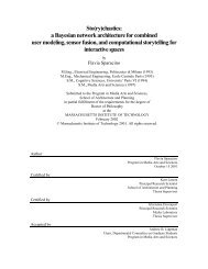
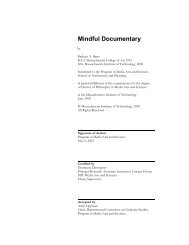
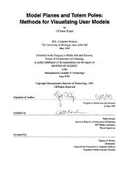
Figure 1: <strong>TechStyle</strong> LED Fabric Schematic<br />
The unit’s output network can be idealized as a circuit of 64 LEDs and wires (Figure<br />
13). The unit’s input network can be idealized as the same schematic of Figure 13,<br />
except all the LEDs are shorted as simply connected wires. These two ideal input and<br />
output circuits can be constructed to test the <strong>TechStyle</strong> system. The 32 I/O lines of the<br />
e-fabric unit are connected to a PIC (see Figure 5).<br />
An example of the unit’s output: how to turn ‘on’ pixel (or LED in the idealized case)<br />
in row1, column5? The answer: pass power (high voltage) to column5 and tie ground<br />
(low voltage) to row1. Moreover, leave the rest of the column and row lines as<br />
unconnected open-circuits (no voltage).<br />
<strong>TechStyle</strong> Page 4
I. Overview<br />
1.1 Purpose and Background<br />
The two main objectives are management and memory. At any time, the e-fabric unit has<br />
two states: pixel input and pixel output. The input state of a unit describes whether or not<br />
each pixel has been pressed down. The output sate of a unit describes whether or not each<br />
pixel has had a color change (on/off). Management is the ability to change and control both<br />
input and output states over time. Memory is the ability to record the history of both input<br />
and output states over time. The management and memory of a single e-fabric unit can be<br />
combined with other Units to create a powerful collective system of pixel input and pixel<br />
output states over time.<br />
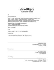
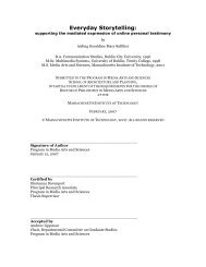
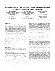
1.2 <strong>System</strong> Overview<br />
The <strong>TechStyle</strong> project can be divided<br />
into two main systems: the CPLD<br />
<strong>System</strong> and the Units <strong>System</strong><br />
(Figure 2).<br />
1.3 <strong>TechStyle</strong> <strong>System</strong> Signals<br />
There are five single-bit signals<br />
Figure 2: <strong>TechStyle</strong> <strong>System</strong> Overview Schematic<br />
(Figure 2) that travel between the<br />
CPLD <strong>System</strong> and the Units <strong>System</strong>. Four are outputs from the CPLD <strong>System</strong> to the Units<br />
system, and one is an input to the CPLD system from the Units system:<br />
• <strong>System</strong> Clock (CLK): Output produced by the CPLD system. It is a 1 Mhz<br />
system clock that synchronizes the system.<br />
• Mode (Mode): Output from the CPLD system. When it is high voltage, the pixel<br />
output is in RAMmode. When it is low voltage, the pixel output is in<br />
AUTOmode (see 3.4 PIC Pixel Output).<br />
• RAM Picture (FPGA_in): Serial output from the CPLD system. It holds pixel<br />
output data used during the RAMmode (see 3.2 CPLD Pixel Output).<br />
• History Trigger (Go): Output from the CPLD system. When it is a high voltage,<br />
it is a sign to the Units system to start the output of its History data (see 3.3<br />
CPLD Pixel Input and Computer Input).<br />
• History (History): Serial data input to the CPLD system. Part of the memory<br />
procedure, it passes data describing pixel output states of all pixels in the<br />
<strong>TechStyle</strong> system over time(see 3.3 CPLD Pixel Input and Computer Input). (An<br />
analogy is that the Units <strong>System</strong> uses this medium to pass color snapshot<br />
pictures of the pixels to the CPLD <strong>System</strong> over time.)<br />
<strong>TechStyle</strong> Page 5
II. Two Major <strong>System</strong> Components<br />
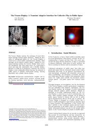
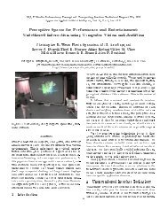
2.1 CPLD <strong>System</strong><br />
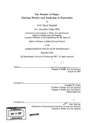
Figure 3: CPLD <strong>System</strong> Schematic<br />
The CPLD <strong>System</strong> is composed of four components: CPLD, RAM, switch, and Computer<br />
(Figure 3). (Note that the RAM is instantiated within the memory of the CPLD, therefore a<br />
physical integrated chip of a RAM is not needed. This allows for nearly instantaneous<br />
communication between the RAM and CPLD.) The CPLD is the primary element of the<br />
CPLD <strong>System</strong>, and the following inputs and outputs shall be referenced to the CPLD.<br />
2.1.1 CPLD <strong>System</strong> Building Blocks<br />
Complex Programmable Logic Devices (CPLD)<br />
Four ATF750C CPLDs were required to fit the VHDL program compiled with<br />
Altera’s MaxPlusII software. The VHDL code was programmed with the Galaxy<br />
software in the <strong>MIT</strong> Electrical Engineering Lab, 38-600.<br />
Switch<br />
The single switch can be implemented with a variety of simple switches, buttons,<br />
latches, etc.<br />
Computer<br />
In the future, the computer may be a part of the management and memory<br />
procedures. It receives and sends data on the pixel output states over time.<br />
<strong>TechStyle</strong> Page 6
2.1.2 CPLD Inputs<br />
There are four inputs to the CPLD (Figure 3). One from the Units <strong>System</strong>, one from the<br />
switch, one from the RAM, and one from the Computer:<br />
• History (History): Serial data input to the CPLD. Part of the memory procedure,<br />
it passes data describing pixel output states of all pixels in the <strong>TechStyle</strong> system<br />
over time(see 3.3 CPLD Pixel Input and Computer Input).<br />
• Switch (mode): User-controlled input from a physical switch to the CPLD. When<br />
it is high voltage, the pixel output is in RAMmode. When it is low voltage, the<br />
pixel output is in AUTOmode (see 3.4 PIC Pixel Output).<br />
• RAM Data (dataRF[7:0]): Input from the RAM. It carries the 8-bit data<br />
referenced by the address signal.<br />
• Computer (Comp): Serial output from the Computer. It holds pixel output data<br />
for every pixel in the <strong>TechStyle</strong> system. In the future, information may be used<br />
during the RAMmode.<br />
2.1.3 CPLD Outputs<br />
There are eight outputs from the CPLD (Figure 3). Four to the Units <strong>System</strong>, three to the<br />
RAM, and one to the Computer:<br />
• <strong>System</strong> Clock (CLK): Output produced by the CPLD. It is a 1 Mhz system clock<br />
that synchronizes the Units <strong>System</strong>.<br />
• Mode (Mode): Output from the CPLD to the Units <strong>System</strong>. When it is high<br />
voltage, the pixel output is in RAMmode. When it is low voltage, the pixel<br />
output is in AUTOmode (see 3.4 PIC Pixel Output).<br />
• RAM Picture (FPGA_in): Serial output from the CPLD to the Units <strong>System</strong>. It<br />
holds pixel output data used during the RAMmode (see 3.2 CPLD Pixel Output).<br />
• History Trigger (Go): Output from the CPLD to the Units <strong>System</strong>. When it is a<br />
high voltage, it is a sign to the Units system to start the output of its History data<br />
(see 3.3 CPLD Pixel Input and Computer Input).<br />
• Write (wr): Output from the CPLD to the RAM. When it is a high voltage, it<br />
allows the referenced RAM address to be written by the signal dataFR.<br />
• RAM Address (addressRAM[7:0]): Output from the CPLD to the RAM. It is an<br />
8-bit signal input to the RAM which references a unique 8-bit data string in the<br />
RAM.<br />
• Write Data (dataFR[7:0]): Output from the CPLD to the RAM. It is an 8-bit<br />
signal which is written, when write is high voltage, to the 8-bit data string<br />
referenced by the RAM address signal.<br />
• Computer (Comp): Serial input from the Computer. It holds data for every pixel<br />
in the <strong>TechStyle</strong> system. Should be identical to the CPLD Pixel Output signal<br />
(see 3.2 CPLD Pixel Output). In the future, information may be used during<br />
RAMmode.<br />
<strong>TechStyle</strong> Page 7
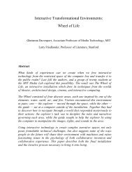
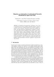
2.2 Units <strong>System</strong><br />
Figure 4: Units <strong>System</strong> Schematic<br />
The Units <strong>System</strong> is composed of multiple identical units connected together (Figure 4).<br />
This makes the design scalable and flexible. Each unit has five I/O signals connected to its<br />
left, right, top, and/or bottom units. The exception is the top-left unit, which connects its<br />
five left I/O signals to the CPLD <strong>System</strong>. A single unit’s internal signal schematic is<br />
provided in Figure 4. In following, the CLK, Mode, and FPGA_in signals are the same for<br />
all units.<br />
Thirty-two signals are connected between the PIC and the fabric unit (Figure 4). (Refer to<br />
Figure 1 for ideal fabric unit schematic.) Sixteen MOSFETs are placed between the PIC<br />
outputs related to the management process, and the fabric unit. In this MOSFET<br />
configuration, a low PIC output seems like an open circuit and a high PIC output seems<br />
like a connection to power. The 8 PIC inputs related to the memory process are connected<br />
to the 8 column ends of the fabric unit. The 8 PIC outputs related to the memory process<br />
are connected to the 8 row lines of the fabric unit.<br />
<strong>TechStyle</strong> Page 8
2.2.1 PIC <strong>System</strong> Building Blocks<br />
PIC Microcontroller<br />
One PIC16F452 is needed for every unit being created. The language used is<br />
Assembly and was compiled with MicroChip’s MPLab. The programmer was<br />
MicroChip’s PIC-StartPlus. (Note that the primary component of the Unit is the<br />
PIC, and the following inputs and outputs shall be referenced to the PIC.)<br />
Metal-Oxide-Semiconductor Field-Effect Transistors (MOSFET)<br />
Sixteen 2N7000 MOSFETs per unit are needed for the pixel outputs to the fabric.<br />
OR Gate<br />
A single dual-input ‘or gate’ per unit is required. At the moment, the 74LS32<br />
quad dual-input ‘or gate’ is being used.<br />
Electronic Fabric<br />
An 8x8 pixel electronic fabric is required per unit. The electronic fabric, custom<br />
designed by Hyun-Yeul Lee (hyun@media.mit.edu), is the cornerstone of the<br />
<strong>TechStyle</strong> <strong>System</strong>.<br />
2.2.2 PIC Inputs<br />
Figure 5: Single Unit Schematic<br />
There are seven inputs to the PIC (Figure 5), including one 8-bit parallel signal from the<br />
Fabric:<br />
• <strong>System</strong> Clock (CLK): Produced by the CPLD system. It is a 1 Mhz system clock<br />
that synchronizes the system.<br />
• Mode (Mode): From the CPLD system. When it is high voltage, the pixel output<br />
is in RAMmode. When it is low voltage, the pixel output is in AUTOmode (see<br />
3.4 PIC Pixel Output).<br />
<strong>TechStyle</strong> Page 9
• RAM Picture (FPGA_in): From the CPLD system. It holds pixel output data<br />
used during the RAMmode (see 3.2 CPLD Pixel Output).<br />
• Top and Left Trigger (TLGo): The ‘or’ of the BotGo of the top unit and the RGo<br />
of the left unit (BotGo or RGo). When its voltage is high, it is a sign to start the<br />
output of its History data (see 3.5 PIC Pixel Input (History)). The ‘or gate’<br />
conserves the limited number of PIC pins used.<br />
• Right History (RHis): Serial data input to the PIC. Part of the memory<br />
procedure, it passes data describing pixel output states of all pixels to the right<br />
and bottom of the right unit (see 3.5 PIC Pixel Input (History)).<br />
• Bottom History (BotHis): Serial data input to the PIC. Part of the memory<br />
procedure, it passes data describing pixel output states of all pixels to the right<br />
and bottom of the bottom unit (see 3.5 PIC Pixel Input (History)).<br />
• Fabric Input [7:0]: Eight parallel inputs from the fabric which is used to<br />
determine the state of all 64 pixels (see 3.4 PIC Pixel Output).<br />
2.2.3 PIC Outputs<br />
There are five outputs from the PIC (Figure 5), including three 8-bit parallel signals from<br />
the fabric unit:<br />
• Right Trigger (RGo): When its voltage is high, it is a sign to the right unit to<br />
start the output of its Right History (see 3.5 PIC Pixel Input (History)).<br />
• Bottom Trigger (BotGo): When its voltage is high, it is a sign to the bottom unit<br />
to start the output of its Bottom History (see 3.5 PIC Pixel Input (History)).<br />
• Fabric Input and Output [7:0]: Eight parallel outputs from the PIC used for both<br />
checking and changing the state of the fabric. The signals for checking the state<br />
of the fabric is output directly to the fabric. The signals for changing the state of<br />
the fabric are passed through eight MOSFETs before being connected to the<br />
fabric.<br />
• Fabric Output Only [7:0]: Eight parallel outputs from the PIC used to change the<br />
state of the fabric. These signals are passed through eight MOSFETs before<br />
being connected to the fabric.<br />
<strong>TechStyle</strong> Page 10
III. <strong>System</strong> Finite State Machine (FSM) Components<br />
3.1 RAM<br />
The RAM is used as a storage device of a single state of all the Units of the <strong>TechStyle</strong><br />
system. It essentially holds a single snapshot ‘picture’ of all the united combined. The<br />
RAM has an 8-bit address with 8 bits<br />
(8bits=1byte) referenced per address.<br />
The memory organization (Figure 6)<br />
is set at nine bytes per unit. Within<br />
each unit’s nine bytes, the first byte<br />
is the unit’s unique id. The next eight<br />
bytes describe the 64 pixels of the<br />
unit. Each byte of these eight bytes<br />
represents a row, starting from<br />
Row0, to Row1, etc., to Row7. The<br />
8-bits within each byte represent the<br />
columns 7 down to 0. A 1 means the<br />
pixel is on, while a 0 means the pixel is off.<br />
Figure 6: RAM Memory Organization<br />
3.2 CPLD Pixel Output<br />
Figure 7: CPLD Serial Output Timing Diagram<br />
(Note that the signal referred to as ‘output’ in this section is<br />
FPGA_in.) The FPGA output has a specified format shown<br />
in Figure 6. The FPGA output is taken directly from the<br />
RAM data. The first unit’s information at address 0x00 listed<br />
in the RAM memory is the initial output (Figure 7). Then<br />
there is a 100-bit pause low before the second unit’s<br />
information is output. This pattern is repeated until all the<br />
Units in the <strong>TechStyle</strong> system have been outputted, and then<br />
this whole cycle repeats from the first unit in the RAM. Each<br />
unit’s information consisted of a start byte of 0xFF, then its 1<br />
byte id, and finally 8 bytes of its pixel information.<br />
The CPLD serial output process (Figure 8) was implemented<br />
as a finite state machine with six states: Initial, Setup, Start,<br />
Byte7, Byte, and Pause1. This process continues whether or<br />
not the mode is high or low voltage, though the PICs only<br />
process the information only when mode is in RAMmode<br />
(mode=’1’).<br />
Figure 8: CPLD Serial Output Process<br />
<strong>TechStyle</strong> Page 11
3.3 CPLD Pixel Input and Computer Input<br />
Figure 9: CPLD Serial Input Timing Diagram<br />
The CPLD input is similar to the CPLD output, but there are many important<br />
differences (Figure 9). The CPLD input’s 10 bytes of unit data is identical in format to<br />
that of the output. Also, the unit data are separated by 100 bits of low. The similarity<br />
ends there.<br />
Knowing the differences are important to understanding the more complex CPLD input<br />
data stream. The input has an End signal of ‘11000011’ (0xC3) connected to the end of<br />
the final unit input. Also, the CPLD input does not automatically continue to repeat<br />
itself. When the CPLD output signal Go is voltage high, it is the sign which allows the<br />
History to start passing its data.<br />
The most important detail is that the CPLD input does not follow the same sequence of<br />
Units as the 3.2 CPLD Output. While the 3.2 CPLD Output followed the order in the<br />
RAM, the CPLD input has a much more complicated, but still organized, order (see 3.5<br />
PIC Output (History)). In the future, the CPLD Input may be passed directly as an<br />
output to the Computer. This sequence of units’s data will be interpreted by the<br />
Computer.<br />
3.4 PIC Pixel Output<br />
Figure 10: PIC Pixel Output<br />
Process<br />
The PIC holds the 64-pixel states in 8 addresses: row0, row1,<br />
etc., to row7. Each address contains a byte of information<br />
which signifies columns 7 down to 0. This format is similar<br />
to that of the RAM Memory Organization (see 3.1 RAM). An<br />
output process was created to interpret all the states of the<br />
pixels (Figure 10). This process initializes at row0, column 0.<br />
It cycles through every column of row0, from 0 to 7,<br />
checking if the pixel is on (‘1’) or off (‘0’). After this, row1 is<br />
checked in the same manner, and then row2, row3, etc.<br />
If the column in a row is determined to be on (‘1’), then the<br />
PIC outputs signals, passing power through its ports to the<br />
specified pixel (see i. Electronic Fabric).<br />
<strong>TechStyle</strong> Page 12
3.4.1 RAMmode<br />
Figure 11: RAMmode Pixel Output Process<br />
The RAMmode output draws the pixel picture specified in the RAM. It takes in the<br />
serial input from the CPLD (see CPLD Pixel Output) and interprets this data into<br />
pixel output states (Figure 11). After the initial state, the process waits for at least<br />
100 low voltage inputs from FPGA_in before moving to the next state. Then it<br />
waits for a Start byte of 8 high voltage inputs from FPGA_in. The next 8 bits are<br />
stored in x[7:0] by function store8inx(). If x is not equal to the id of the specific<br />
unit, then it moves back to state initial. Otherwise, it moves on to repeating a<br />
pattern of storing 8 bits into x, and then storing this byte into all eight rows. This<br />
process is executed only when the mode is voltage high.<br />
3.4.2 AUTOmode<br />
The AUTOmode of pixel output is initiated when the mode signal is low voltage. In<br />
this state, the user controls which pixels turn on or off by pressing down on the<br />
fabric. The overall logic is simple at every pixel press: 1) If pixel was off, then turn<br />
it on. 2) If pixel was on, then turn it off. Every pixel is analogous to a light switch.<br />
<strong>TechStyle</strong> Page 13
3.5 PIC Pixel Input (History)<br />
Figure 12: PIC Pixel History Timing Diagram<br />
The PIC Pixel History data starts to pass only when the<br />
signal TLGo is high voltage. The History signal follows a<br />
general guideline:<br />
1. Start Signal 0xFF<br />
2. Own Unit's 8-bit ID<br />
3. Own Unit's 64-bit Pixel Information<br />
4. Right Signal, or if X ~0xF0, or if XX ~0xFF<br />
5. (If not XX) Bottom Signal, or if X ~ 0xF0<br />
This pattern can be seen in the PIC<br />
Pixel History Timing Diagram<br />
(Figure 12). In the diagram, the<br />
bottom signal represents the signal<br />
format if there were no Units<br />
connected to the top and bottom<br />
(XX). The top signal shows the<br />
format of the history signal if a unit<br />
was connected to either the top or<br />
bottom of the current unit.<br />
An important detail in the history<br />
signal is that the ‘right signal’ is not<br />
limited to only 10 bytes, the standard<br />
size of one unit. The ‘right signal’<br />
contains all the pixel data of all the<br />
units to its right and bottom.<br />
Therefore, it most likely has many<br />
signals within it. The same principle<br />
applies to the ‘bottom signal’.<br />
The PIC Pixel History Process<br />
(Figure 13) follows the general<br />
guideline of the Present Unit, Right Signal,<br />
and then Bottom Signal order mentioned<br />
previously.<br />
Figure 13: PIC Pixel History Process<br />
<strong>TechStyle</strong> Page 14
IV. Challenges<br />
5.1 Challenges<br />
The fabric was the largest challenge because of its multiple unknowns. The conductive fiber<br />
has variable resistance which varies the speed at which pixels turn on. This makes it difficult<br />
during implementation of the pixel output, when individual pixels do not visually turn on as a<br />
group consistently. A phenomenon termed ‘pixel leakage’ is a problem that may be due to too<br />
much power. This word describes how turning on one pixel, may slight change the color of its<br />
surrounding pixels.<br />
Another large challenge was in increasing the power output to the fabric. The maximum<br />
voltage allowed to drive the PIC is 7.5 V, but the power wanted for fabric output is 10-15V.<br />
The higher amount of voltage increases the speed that the pixel turns on. Ideally, one wants<br />
increased speed to decrease, or possibly nullify, the variance of resistance within the fabric.<br />
The first method tried was a MOSFET with the PIC output tied to the gate, and the fabric line<br />
tied to the base. The MOSFETs of the column have power tied to the drain, and the MOSFETs<br />
of the row have ground tied to the drain. Basically, the key idea was to set power at 10V. When<br />
the PIC signal is low, there will be an open circuit, and when the PIC signal is high, power for<br />
the column, or ground for the rows, will be passed through the circuit. Unfortunately, the<br />
MOSFET output is limited by the gate voltage. For example, when one passes a 5V PIC signal<br />
to the gate, the MOSFET output is still ~3.5V even when the drain is tied to 10V.<br />
The second method was utilizing op-amps to increase the voltage output to the fabric. The<br />
open circuit voltage was increased to over 10V, but the output drops to ~3V when the op-amp<br />
output is connected to the fabric. This may be due to an output resistance that changes the<br />
voltage and current.<br />
The third method involves focusing upon increasing the current, instead of the voltage, through<br />
BJTs. A simple common-emitter amplifier configuration should be enough to greatly increase<br />
the current, and therefore the power. This plan has will be tested on May 14 th .<br />
V. Conclusion<br />
The memory portion of the <strong>TechStyle</strong> <strong>System</strong> works as expected. It monitors the history of the<br />
fabric, and sends data of the pixel output states in a flexible manner.<br />
The management portion related to the input states of the <strong>TechStyle</strong> system works as expected.<br />
Therefore, the sense of whether a pixel has been pressed within all units is known exactly.<br />
The management portion related to the output states of the <strong>TechStyle</strong> system does not always<br />
work as expected. The change of pixel color has not been faultless. The memory of the system<br />
has proved to be more resilient. This is mainly due to the challenges of the electronic fabric<br />
(see 5.1 Challenges). While the digital signals passed to the fabric units seem to be as planned,<br />
<strong>TechStyle</strong> Page 15
the electronic fabric does not always respond with changes in color of an expected manner.<br />
The <strong>TechStyle</strong> is expected to work with an idealized schematic such as in Figure 1, but the<br />
reality of electronic fabric is not ideal.<br />
Further work and communication with the Computer is expected in the future, as occasionally<br />
mentioned throughout this document. Eventually, the management and memory of the<br />
<strong>TechStyle</strong> system would be controlled by a user interface application within the computer.<br />
Appendix A: Electronic Fabric with Simultaneous Input and Output<br />
Implementation<br />
Scalability<br />
The scalability issue is approached by<br />
using a pixel layout like a Cartesian<br />
coordinate system. The pixel layout is<br />
similar to the implementation used by a<br />
normal television and computer screen.<br />
The picture to the right is an example of<br />
the current pixel system being<br />
researched.<br />
In the picture, each dark blue square<br />
represents one pixel and each pixel is a<br />
half inch by a half inch. Within each<br />
dark blue square is a one-eighth by oneeighth<br />
light blue square which represents the output square. There are three input points<br />
within each dark blue square pixel and each one is represented as a small yellow square. To<br />
improve robustness, three inputs per pixel were chosen in the case that if one input square<br />
failed, two other points would still be operational.<br />
This pixel design is ideal because it can be hypothetically expanded infinitesimally. Also,<br />
in viewing this ‘x number’ by ‘y number’ pixel design as an ‘x number’ by ‘y number’<br />
Cartesian coordinate system, it is easy to manage the output and input signals from a higher<br />
level thought process.<br />
Simultaneous Input and Output<br />
The output is a change of color within the output square.<br />
In the pictures to the right, the overlap of the blue lines<br />
represents the output square that is identical within each<br />
pixel. The top picture to the right is an example of an<br />
output square that is inactivated. The bottom picture is an<br />
example of an output square that is activated.<br />
<strong>TechStyle</strong> Page 16
The underlying idea for the output requires two basic material preparations: heat-sensitive<br />
dye and wires woven into the fabric. The electronic fabric<br />
used by this project has by streaked with custom designed<br />
heat-sensitive dye. At this time, the experimental fabric<br />
has been coated with dye that is blue at room temperature<br />
and white at a higher temperature. Wires are woven<br />
within the fabric and current is passed through these<br />
wires to induce heat dissipation. This heat causes an<br />
increase in temperature at a pixel point and leads to a<br />
change in color at an output pixel.<br />
ICs Separate from Fabric<br />
The input senses whether the fabric has been<br />
pressed down upon. The input necessitates<br />
two layers of woven fabric and a foam layer,<br />
as shown in the picture to the left. As the top<br />
fabric layer is pressed down, its woven wires<br />
come in contact with the bottom layer’s<br />
woven wires. The current sent through the top<br />
wires flows into the bottom wires. This is then<br />
detected by integrated circuits connected at<br />
the ends of the bottom wires.<br />
The integrated circuits used during this project were not woven underneath or on the<br />
circuit. The integrated circuits are placed within a circuit board that can be hidden<br />
anywhere within the object the electronic fabric is covering.<br />
Appendix B: VHDL [CPLD] Code<br />
-- FRsystem.vhd<br />
-- Abraham Hsu<br />
-- April, 2005<br />
-- Student, <strong>MIT</strong><br />
-- Program Description:<br />
-- This program interacts with a ROM and the mother PIC unit. It outputs<br />
the<br />
-- information from the ROM as a serial data on one line to the mother<br />
unit.<br />
--<br />
library IEEE;<br />
use IEEE.std_logic_1164.all;<br />
use IEEE.std_logic_arith.all;<br />
<strong>TechStyle</strong> Page 17
use IEEE.std_logic_unsigned.all; -- Needed for "+" with<br />
std_logic_vectors<br />
library work;<br />
--use work.new_func.all;<br />
entity FRsystem is<br />
port(<br />
clk : in std_logic;<br />
mode : in std_logic;<br />
-- ROM signals<br />
dataRF : in std_logic_vector(7 downto 0);<br />
wr : out std_logic;<br />
addressRAM : out std_logic_vector(7 downto 0);<br />
dataFR : out std_logic_vector(7 downto 0);<br />
-- PIC signal<br />
output : out std_logic<br />
);<br />
end entity FRsystem;<br />
architecture component_a of FRsystem is<br />
-- Variables<br />
signal address, data : std_logic_vector(7 downto 0);<br />
-- States for FR<strong>System</strong>Output FSM<br />
type StateType is (Initial, Setup, Start, Byte7, Byte, Pause1);<br />
signal S_s : StateType;<br />
begin<br />
-- Internal Signals<br />
addressMax
else S_s S_s if (address=addressMax) then<br />
S_s
end architecture;<br />
Appendix C: Assembly [PIC] Code<br />
; PIC.asm For 8x8Pixel Code<br />
; Abraham Hsu<br />
; April 2005<br />
; <strong>MIT</strong>, Student<br />
list p=18f452<br />
#include "p18f452.inc"<br />
; __CONFIG _CP_OFF&_WDT_OFF&_PWRTE_OFF&_RC_OSC<br />
radix hex<br />
; Memory Map-------------------------------------------------<br />
inCol equ PORTB<br />
inRow equ PORTC<br />
outCol equ PORTD<br />
;inCol equ 0xA0<br />
;inRow equ 0xA1<br />
;outCol equ 0xA2<br />
;outRow equ 0xA3<br />
col equ 0xA4<br />
row equ 0xA5<br />
rowNum equ 0xA6<br />
reg equ 0xA7<br />
address equ 0xA8<br />
state equ 0xA9<br />
row0 equ 0x80<br />
row1 equ 0x81<br />
row2 equ 0x82<br />
row3 equ 0x83<br />
row4 equ 0x84<br />
row5 equ 0x85<br />
row6 equ 0x86<br />
row7 equ 0x87<br />
stat0 equ 0x90<br />
stat1 equ 0x91<br />
stat2 equ 0x92<br />
stat3 equ 0x93<br />
stat4 equ 0x94<br />
stat5 equ 0x95<br />
stat6 equ 0x96<br />
stat7 equ 0x97<br />
id equ 0xB0<br />
nStart equ 0xB1<br />
nPause equ 0xB2<br />
x equ 0xB3<br />
<strong>TechStyle</strong> Page 20
;------------------------------------------------------------<br />
org 0x000<br />
goto start<br />
org 0x004<br />
goto start<br />
; Program Starts<br />
start<br />
;Clear Registers------------------------------------<br />
clrf row0<br />
clrf row1<br />
clrf row2<br />
clrf row3<br />
clrf row4<br />
clrf row5<br />
clrf row6<br />
clrf row7<br />
clrf stat0<br />
clrf stat1<br />
clrf stat2<br />
clrf stat3<br />
clrf stat4<br />
clrf stat5<br />
clrf stat6<br />
clrf stat7<br />
;--------------------------------------------<br />
movlw 0x01<br />
movwf id<br />
;A0 CLK In<br />
;A1 History Out<br />
;A2 FPGA_in In<br />
;A3 Mode In<br />
;A4 TLGo In<br />
;A5 RightGo Out<br />
;inCol<br />
clrf PORTB<br />
movlw 0xFF<br />
movwf TRISB<br />
clrf PORTB ;portb input<br />
;inRow<br />
clrf PORTC<br />
movlw 0x00<br />
movwf TRISC<br />
clrf PORTC ;portc output<br />
;outCol<br />
clrf PORTD<br />
movlw 0x00<br />
movwf TRISD<br />
clrf PORTD ;portd output<br />
<strong>TechStyle</strong> Page 21
;E0 RightHis In<br />
;E1 BottGo Out<br />
;E2 BottIn In<br />
clrf PORTA<br />
movlw b'00011101'<br />
movwf TRISA<br />
clrf PORTA ;portd output<br />
clrf PORTE<br />
movlw b'00000101'<br />
movwf TRISE<br />
clrf PORTE ;portd outpu<br />
;Testing Code------------------------------------------<br />
; goto x7<br />
; bcf<br />
; movlw 0x01<br />
; movwf mode<br />
;Mode SubRoutine-------------------------------------<br />
mode btfsc PORTA, 3 ;Mode=0?<br />
goto x7 ;FALSE<br />
goto input ;TRUE<br />
;Input Program---------------------------------------<br />
input movlw 0x01<br />
movwf col<br />
movwf row<br />
clrf rowNum<br />
movf row,w<br />
movwf inRow<br />
movf stat0,w<br />
movwf state<br />
input2 movf col,w<br />
andwf state,w ;value in WREG<br />
tstfsz WREG ;if (state0)<br />
goto state1 ;FALSE<br />
goto state0 ;TRUE<br />
seeCol movlw 0x80 ;if (col='7')<br />
cpfseq col<br />
goto addcolI ;FALSE<br />
;TRUE<br />
cpfseq row ;if (row='7')<br />
goto addRowI ;FALSE<br />
goto output ;TRUE<br />
;states Subroutine----------------------------------------------<br />
state0 movf col,w ;if (row1[col] = 0)<br />
andwf inCol,w<br />
xorwf col,w<br />
tstfsz WREG ;if (press=1?)<br />
goto seeCol ;FALSE<br />
;TRUE<br />
call compBit<br />
<strong>TechStyle</strong> Page 22
call compStat<br />
goto seeCol<br />
state1 movf col,w ;if (row1[col] = 0)<br />
andwf inCol,w<br />
tstfsz WREG ;if (press=0?)<br />
goto seeCol ;FALSE<br />
;TRUE<br />
call compStat<br />
goto seeCol<br />
;compStat Subroutine-------------------------------------------<br />
compStat movlw 0x90<br />
addwf rowNum,w ; unknown address is in WREG, how<br />
to retrieve the data from this address?<br />
movwf FSR1L, ACCESS ; load address into FSR0L<br />
clrf FSR1H, ACCESS ; clear the four most significant<br />
bits of FSR0<br />
call getStat<br />
movf col,w<br />
xorwf state,w ;value in WREG<br />
movwf INDF1, ACCESS ; fetch value pointed to by FSR0<br />
return<br />
;compBit Subroutine--------------------------------------------<br />
compBit movlw 0x80<br />
addwf rowNum,w ; unknown address is in WREG, how<br />
to retrieve the data from this address?<br />
movwf FSR1L, ACCESS ; load address into FSR0L<br />
clrf FSR1H, ACCESS ; clear the four most significant<br />
bits of FSR0<br />
call loadRow<br />
movf col,w<br />
xorwf reg,w ;value in WREG<br />
movwf INDF1, ACCESS ; fetch value pointed to by FSR0<br />
return<br />
;getStat Subroutine---------------------------------------------<br />
getStat movlw 0x90<br />
addwf rowNum,w ; unknown address is in WREG, how<br />
to retrieve the data from this address?<br />
movwf FSR0L, ACCESS ; load address into FSR0L<br />
clrf FSR0H, ACCESS ; clear the four most significant<br />
bits of FSR0<br />
movf INDF0, w, ACCESS ; fetch value pointed to by FSR0<br />
movwf state<br />
return<br />
;getRow Subroutine----------------------------------------------<br />
loadRow movlw 0x80<br />
addwf rowNum,w ; unknown address is in WREG, how<br />
to retrieve the data from this address?<br />
movwf FSR0L, ACCESS ; load address into FSR0L<br />
clrf FSR0H, ACCESS ; clear the four most significant<br />
bits of FSR0<br />
<strong>TechStyle</strong> Page 23
movf INDF0, w, ACCESS ; fetch value pointed to by FSR0<br />
movwf reg<br />
return<br />
;Add Subroutines---------------------- ---------------------------<br />
addcolI rlncf col<br />
goto input2<br />
addRowI rlncf row<br />
incf rowNum<br />
movf row,w<br />
movwf inRow<br />
call getStat<br />
movlw 0x01<br />
movwf col<br />
goto input2<br />
;Output Program---------------------------------------<br />
output movlw 0x01<br />
movwf col<br />
movwf row<br />
clrf rowNum<br />
movf row0,w<br />
movwf reg<br />
output2 movf col,w ;if (row1[col] = 0)<br />
andwf reg,w<br />
tstfsz WREG<br />
call light ;FALSE<br />
;TRUE<br />
movlw 0x80 ;if (col='7')<br />
cpfseq col<br />
goto addcol ;FALSE<br />
;TRUE<br />
cpfseq row ;if (row='7')<br />
goto addRow ;FALSE<br />
goto mode ;TRUE<br />
;Add Subroutines---------------------- ---------------------------<br />
addcol rlncf col<br />
goto output2<br />
addRow rlncf row<br />
incf rowNum<br />
movlw 0x01<br />
movwf col<br />
call loadRow<br />
goto output2<br />
;Light Subroutine-------------------------------------------<br />
light movf col,w<br />
movwf outCol<br />
movf row,w<br />
; movwf outRow<br />
nop<br />
<strong>TechStyle</strong> Page 24
nop<br />
; call delay<br />
clrf outCol<br />
; clrf outRow<br />
return<br />
;Delay Subroutine------------------------------------------------<br />
;delay clrf TMR0<br />
;again btfss TMR0,3 ;This makes a delay of internal clk*16*2<br />
; goto again<br />
; return<br />
;Clock Subroutine-----------------------------------------------<br />
;rising edge: 1)Make sure is in low 2)Wait for clk to be high again<br />
clock btfsc PORTA, 0 ;clk=0?<br />
goto clock ;FALSE<br />
;TRUE<br />
clock2 btfss PORTA, 0 ;clk=1?<br />
goto clock2 ;FALSE<br />
return ;TRUE<br />
;FPGA Output Subroutine-----------------------------------------<br />
Foutput movlw b'01100100'<br />
movwf nPause<br />
movlw 0x08<br />
movwf nStart<br />
clrf stat0<br />
clrf stat1<br />
clrf stat2<br />
clrf stat3<br />
clrf stat4<br />
clrf stat5<br />
clrf stat6<br />
clrf stat7<br />
Pause ;call clock<br />
btfsc PORTA, 2 ;FPGA_in=0?<br />
goto Pause ;FALSE<br />
;TRUE<br />
decfsz nPause ;(nPause=0)?<br />
goto Pause ;FALSE<br />
;TRUE<br />
Start ;call clock<br />
btfss PORTA, 2 ;FPGA_in=1?<br />
goto Foutput ;FALSE<br />
;TRUE<br />
decfsz nStart ;(nPause=0)?<br />
goto Start ;FALSE<br />
;True<br />
;idTest SubRoutine-------------------------------------<br />
call x7<br />
movf x ;id=x?<br />
xorwf id,w<br />
tstfsz WREG<br />
goto Foutput ;FALSE<br />
goto write64 ;TRUE<br />
;write64---------------------------------------------------------<br />
<strong>TechStyle</strong> Page 25
write64 call x7<br />
movf x<br />
movwf row0<br />
call x7<br />
movf x<br />
movwf row1<br />
call x7<br />
movf x<br />
movwf row2<br />
call x7<br />
movf x<br />
movwf row3<br />
call x7<br />
movf x<br />
movwf row4<br />
call x7<br />
movf x<br />
movwf row5<br />
call x7<br />
movf x<br />
movwf row6<br />
call x7<br />
movf x<br />
movwf row7<br />
goto output<br />
;x SubRoutine-----------------------------------------------------<br />
;Stores the next 8 bits in address x<br />
x7 call clock<br />
btfss PORTA, 2 ;FPGA_in=1?<br />
goto x7F ;FALSE<br />
bsf x,7 ;TRUE<br />
goto x6<br />
x7F bcf x,7<br />
x6 call clock<br />
btfss PORTA, 2 ;FPGA_in=1?<br />
goto x6F ;FALSE<br />
bsf x,6 ;TRUE<br />
goto x5<br />
x6F bcf x,6<br />
x5 call clock<br />
btfss PORTA, 2 ;FPGA_in=1?<br />
goto x5F ;FALSE<br />
bsf x,5 ;TRUE<br />
goto x4<br />
x5F bcf x,5<br />
<strong>TechStyle</strong> Page 26
x4 call clock<br />
btfss PORTA, 2 ;FPGA_in=1?<br />
goto x4F ;FALSE<br />
bsf x,4 ;TRUE<br />
goto x3<br />
x4F bcf x,4<br />
x3 call clock<br />
btfss PORTA, 2 ;FPGA_in=1?<br />
goto x3F ;FALSE<br />
bsf x,3 ;TRUE<br />
goto x2<br />
x3F bcf x,3<br />
x2 call clock<br />
btfss PORTA, 2 ;FPGA_in=1?<br />
goto x2F ;FALSE<br />
bsf x,2 ;TRUE<br />
goto x1<br />
x2F bcf x,2<br />
x1 call clock<br />
btfss PORTA, 2 ;FPGA_in=1?<br />
goto x1F ;FALSE<br />
bsf x,1 ;TRUE<br />
goto x0<br />
x1F bcf x,1<br />
x0 call clock<br />
btfss PORTA, 2 ;FPGA_in=1?<br />
goto x0F ;FALSE<br />
bsf x,0 ;TRUE<br />
return<br />
x0F bcf x,0<br />
return<br />
end<br />
<strong>TechStyle</strong> Page 27