A Low Cost Watt-Hour Energy Meter Based on the ADE7757 ...
A Low Cost Watt-Hour Energy Meter Based on the ADE7757 ...
A Low Cost Watt-Hour Energy Meter Based on the ADE7757 ...

You also want an ePaper? Increase the reach of your titles
YUMPU automatically turns print PDFs into web optimized ePapers that Google loves.
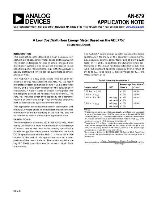
AN-679<br />
APPLICATION NOTE<br />
One Technology Way • P.O. Box 9106 • Norwood, MA 02062-9106 • Tel: 781/329-4700 • Fax: 781/326-8703 • www.analog.com<br />
A <str<strong>on</strong>g>Low</str<strong>on</strong>g> <str<strong>on</strong>g>Cost</str<strong>on</strong>g> <str<strong>on</strong>g>Watt</str<strong>on</strong>g>-<str<strong>on</strong>g>Hour</str<strong>on</strong>g> <str<strong>on</strong>g>Energy</str<strong>on</strong>g> <str<strong>on</strong>g>Meter</str<strong>on</strong>g> <str<strong>on</strong>g>Based</str<strong>on</strong>g> <strong>on</strong> <strong>the</strong> <strong>ADE7757</strong><br />
INTRODUCTION<br />
This applicati<strong>on</strong> note describes a high accuracy, low<br />
cost, single-phase, power meter based <strong>on</strong> <strong>the</strong> <strong>ADE7757</strong>.<br />
The meter is designed for use in single-phase, 2-wire<br />
distributi<strong>on</strong> systems. The design can be adapted to suit<br />
specific regi<strong>on</strong>al requirements, e.g., in <strong>the</strong> U.S. power is<br />
usually distributed for residential customers as singlephase,<br />
3-wire.<br />
The <strong>ADE7757</strong> is a low cost, single-chip soluti<strong>on</strong> for<br />
electrical energy measurement. The <strong>ADE7757</strong> is a highly<br />
integrated system comprised of two ADCs, a reference<br />
circuit, and a fixed DSP functi<strong>on</strong> for <strong>the</strong> calculati<strong>on</strong> of<br />
real power. A highly stable oscillator is integrated into<br />
<strong>the</strong> design to provide <strong>the</strong> necessary clock for <strong>the</strong> IC. The<br />
<strong>ADE7757</strong> includes direct drive capability for electromechanical<br />
counters and a high frequency pulse output for<br />
both calibrati<strong>on</strong> and system communicati<strong>on</strong>.<br />
This applicati<strong>on</strong> note should be used in c<strong>on</strong>juncti<strong>on</strong> with<br />
<strong>the</strong> <strong>ADE7757</strong> Data Sheet. The data sheet provides detailed<br />
informati<strong>on</strong> <strong>on</strong> <strong>the</strong> functi<strong>on</strong>ality of <strong>the</strong> <strong>ADE7757</strong> and will<br />
be referenced several times in this applicati<strong>on</strong> note.<br />
DESIGN GOALS<br />
The Internati<strong>on</strong>al Standard IEC 61036 (2000-09), Alternating<br />
Current Static <str<strong>on</strong>g>Watt</str<strong>on</strong>g>-<str<strong>on</strong>g>Hour</str<strong>on</strong>g> <str<strong>on</strong>g>Meter</str<strong>on</strong>g>s for Active <str<strong>on</strong>g>Energy</str<strong>on</strong>g><br />
(Classes 1 and 2), was used as <strong>the</strong> primary specificati<strong>on</strong><br />
for this design. For readers more familiar with <strong>the</strong> ANSI<br />
C12.16 specificati<strong>on</strong>, see <strong>the</strong> ANSI C12.16 and IEC 61036<br />
secti<strong>on</strong> at <strong>the</strong> end of this applicati<strong>on</strong> note for a comparis<strong>on</strong><br />
of <strong>the</strong> two standards. The secti<strong>on</strong> explains <strong>the</strong><br />
key IEC 61036 specificati<strong>on</strong>s in terms of <strong>the</strong>ir ANSI<br />
equivalents.<br />
REV. 0<br />
By Stephen T. English<br />
The <strong>ADE7757</strong> board design greatly exceeds this basic<br />
specificati<strong>on</strong> for many of <strong>the</strong> accuracy requirements,<br />
e.g., accuracy at unity power factor and at a low power<br />
factor (PF = ±0.5). In additi<strong>on</strong>, <strong>the</strong> dynamic range performance<br />
of <strong>the</strong> meter has been extended to 400. The<br />
IEC 61036 standard specifies accuracy over a range of<br />
5% Ib to I MAX (see Table I). Typical values for I MAX are<br />
400% to 600% of Ib.<br />
Table I. Accuracy Requirements<br />
Percentage Error Limits 3<br />
Current Value 1 PF 2 Class 1 Class 2<br />
0.05 lb < I < 0.1 lb 1 ±1.5% ±2.5%<br />
0.1 lb < I < I MAX 1 ±1.0% ±2.0%<br />
0.1 lb < I < 0.2 lb 0.5 Lag ±1.5% ±2.5%<br />
0.8 Lead ±1.5%<br />
0.2 lb < I < I MAX 0.5 Lag ±1.0% ±2.0%<br />
0.8 Lead ±1.0%<br />
NOTES<br />
1 The current ranges for specified accuracy shown in Table I are expressed<br />
in terms of <strong>the</strong> basic current (Ib). The basic current is defined in IEC 61036<br />
(2000–09) Secti<strong>on</strong> 3.5.1.1 as <strong>the</strong> value of current in accordance with which<br />
<strong>the</strong> relevant performance of a direct c<strong>on</strong>necti<strong>on</strong> meter is fixed. I MAX is <strong>the</strong><br />
maximum current at which accuracy is maintained.<br />
2 Power factor (PF) in Table I relates <strong>the</strong> phase relati<strong>on</strong>ship between <strong>the</strong><br />
fundamental voltage (45 Hz to 65 Hz) and current waveforms. PF, in this<br />
case, can be simply defined as PF = cos(), where is <strong>the</strong> phase angle<br />
between pure sinusoidal current and voltage.<br />
3 Class index is defined in IEC 61036 (2000–09) Secti<strong>on</strong> 3.5.5, Page 27, as<br />
<strong>the</strong> limits of <strong>the</strong> permissible percentage error. The percentage error is<br />
defined as:<br />
Percentage Error<br />
<str<strong>on</strong>g>Energy</str<strong>on</strong>g> Registered by <str<strong>on</strong>g>Meter</str<strong>on</strong>g> – True <str<strong>on</strong>g>Energy</str<strong>on</strong>g><br />
= ×100%<br />
True <str<strong>on</strong>g>Energy</str<strong>on</strong>g>
AN-679<br />
<br />
<br />
<br />
<br />
The schematic in Figure 1 shows <strong>the</strong> implementati<strong>on</strong> of<br />
a simple, low cost, watt-hour meter using <strong>the</strong> <strong>ADE7757</strong>.<br />
A shunt is used to provide <strong>the</strong> current-to-voltage c<strong>on</strong>versi<strong>on</strong><br />
needed by <strong>the</strong> <strong>ADE7757</strong> and a simple divider<br />
network attenuates <strong>the</strong> line voltage. The energy register<br />
(kWh) is a simple electromechanical counter that uses<br />
a 2-phase stepper motor. The <strong>ADE7757</strong> provides direct<br />
drive capability for this type of counter. The <strong>ADE7757</strong><br />
also provides a high frequency output at <strong>the</strong> CF pin for<br />
a selected meter c<strong>on</strong>stant of 1600 imp/kWh. Thus, a<br />
high frequency output is available at <strong>the</strong> LED and optoisolator<br />
output. This high frequency output is used to<br />
speed up <strong>the</strong> calibrati<strong>on</strong> process and provides a means<br />
of quickly verifying meter functi<strong>on</strong>ality and accuracy in<br />
a producti<strong>on</strong> envir<strong>on</strong>ment. The meter is calibrated by<br />
varying <strong>the</strong> line voltage attenuati<strong>on</strong> using <strong>the</strong> series<br />
resistor network R5 to R16. Figure 1 illustrates <strong>the</strong>se<br />
resistors as a potentiometer.<br />
<br />
<br />
<br />
<br />
<br />
<br />
<br />
<br />
<br />
<br />
<br />
<br />
<br />
<br />
<br />
<br />
<br />
<br />
<br />
<br />
<br />
<br />
<br />
<br />
<br />
<br />
<br />
<br />
<br />
<br />
<br />
<br />
<br />
<br />
<br />
<br />
<br />
<br />
<br />
<br />
<br />
<br />
<br />
<br />
<br />
<br />
<br />
<br />
<br />
<br />
<br />
<br />
<br />
<br />
<br />
–2–<br />
<br />
<br />
<br />
<br />
<br />
<br />
<br />
<br />
<br />
<br />
<br />
<br />
<br />
<br />
<br />
<br />
<br />
<br />
<br />
<br />
<br />
<br />
<br />
<br />
<br />
<br />
<br />
<br />
<br />
<br />
<br />
Figure 1. Single-Phase <str<strong>on</strong>g>Watt</str<strong>on</strong>g>-<str<strong>on</strong>g>Hour</str<strong>on</strong>g> <str<strong>on</strong>g>Meter</str<strong>on</strong>g> <str<strong>on</strong>g>Based</str<strong>on</strong>g> <strong>on</strong> <strong>the</strong> <strong>ADE7757</strong><br />
<br />
<br />
DESIGN EQUATIONS<br />
The <strong>ADE7757</strong> produces an output frequency that is proporti<strong>on</strong>al<br />
to <strong>the</strong> time average value of <strong>the</strong> product of two<br />
voltage signals. The input voltage signals are applied at<br />
V1 and V2. The detailed functi<strong>on</strong>ality of <strong>the</strong> <strong>ADE7757</strong><br />
is explained in <strong>the</strong> Theory of Operati<strong>on</strong> secti<strong>on</strong> of <strong>the</strong><br />
<strong>ADE7757</strong> Data Sheet. The <strong>ADE7757</strong> Data Sheet also<br />
provides an equati<strong>on</strong> that relates <strong>the</strong> output frequency<br />
<strong>on</strong> F1 and F2 (counter drive) to <strong>the</strong> product of <strong>the</strong> rms<br />
signal levels at V1 and V2. This equati<strong>on</strong> is shown here<br />
again for c<strong>on</strong>venience and will be used to determine <strong>the</strong><br />
correct signal scaling at V2 in order to calibrate <strong>the</strong> meter<br />
to a fixed c<strong>on</strong>stant.<br />
515.84 × V1RMS × V 2RMS × F1–4<br />
Freq =<br />
2<br />
V<br />
( REF )<br />
<br />
(1)<br />
REV. 0
The meter shown in Figure 1 is designed to operate at<br />
a line voltage of 220 V and a maximum current (I MAX) of<br />
30 A. However, by correctly scaling <strong>the</strong> signals <strong>on</strong><br />
Channel 1 and Channel 2, a meter operating at any line<br />
voltage and maximum current could be designed.<br />
The four frequency opti<strong>on</strong>s available <strong>on</strong> <strong>the</strong> <strong>ADE7757</strong><br />
will allow similar meters (i.e., direct counter drive) with<br />
an I MAX of up to 120 A to be designed. The basic current<br />
(Ib) for this meter is selected as 5 A and <strong>the</strong> current range<br />
for accuracy will be 2% of Ib to I MAX, or a dynamic range<br />
of 400:1 (75 mA to 30 A).<br />
The electromechanical register (kWh) will have a<br />
c<strong>on</strong>stant of 100 imp/kWh, i.e., 100 impulses from <strong>the</strong><br />
<strong>ADE7757</strong> will be required to register 1 kWh. IEC 61036<br />
Secti<strong>on</strong> 4.2.11 specifies that electromagnetic registers<br />
have <strong>the</strong>ir lowest values numbered in ten divisi<strong>on</strong>s, each<br />
divisi<strong>on</strong> being subdivided into ten parts. Hence, a display<br />
with five plus <strong>on</strong>e digits is used, i.e., 10,000s, 1,000s,<br />
100s, 10s, 1s, and 1/10s. The meter c<strong>on</strong>stant (for calibrati<strong>on</strong><br />
and test) is selected as 1600 imp/kWh.<br />
Figure 2. Final Implementati<strong>on</strong> of <strong>ADE7757</strong> <str<strong>on</strong>g>Meter</str<strong>on</strong>g><br />
*IEC 61036, Ed 2.1, Secti<strong>on</strong> 4, 4, 1, 2, Table 8<br />
REV. 0<br />
–3–<br />
AN-679<br />
<strong>ADE7757</strong> Reference<br />
The <strong>on</strong>-chip reference circuit of <strong>the</strong> <strong>ADE7757</strong> has a temperature<br />
coefficient of typically 30 ppm/°C. However,<br />
<strong>on</strong> A Grade parts, this specificati<strong>on</strong> is not guaranteed<br />
and may be as high as 80 ppm/°C. At 80 ppm/°C, <strong>the</strong><br />
<strong>ADE7757</strong> error at –20°C/+60°C could be as high as 0.65%,<br />
assuming a calibrati<strong>on</strong> at 25°C. An opti<strong>on</strong>al external<br />
reference can be used by c<strong>on</strong>necting it to <strong>the</strong> REF IN/OUT<br />
pin for improved accuracy.<br />
Shunt Selecti<strong>on</strong><br />
The shunt size (350 ) is selected to maximize <strong>the</strong> use<br />
of <strong>the</strong> dynamic range <strong>on</strong> Channel V1 (current channel).<br />
However, <strong>the</strong>re are some important c<strong>on</strong>siderati<strong>on</strong>s when<br />
selecting a shunt for an energy metering applicati<strong>on</strong>.<br />
First, minimize <strong>the</strong> power dissipati<strong>on</strong> in <strong>the</strong> shunt. The<br />
maximum rated current for this design is 30 A; <strong>the</strong>refore,<br />
<strong>the</strong> maximum power dissipated in <strong>the</strong> shunt is 30 A 2 <br />
350 = 315 mW. IEC 61036 calls for a maximum power<br />
dissipati<strong>on</strong> of 4.0 VA* in <strong>the</strong> current circuit. Sec<strong>on</strong>d, <strong>the</strong><br />
higher power dissipati<strong>on</strong> may make it difficult to manage<br />
<strong>the</strong> <strong>the</strong>rmal issues. Although <strong>the</strong> shunt is manufactured<br />
from Manganin material, which is an alloy with a low<br />
temperature coefficient of resistance, high temperatures<br />
may cause significant error at heavy loads.<br />
A third c<strong>on</strong>siderati<strong>on</strong> is <strong>the</strong> ability of <strong>the</strong> meter to<br />
resist attempts to tamper by shorting <strong>the</strong> phase circuit.<br />
With a very low value of shunt resistance, <strong>the</strong> effects of<br />
externally shorting <strong>the</strong> shunt are very much minimized.<br />
Therefore, <strong>the</strong> shunt should always be made as small as<br />
possible, but this must be offset against <strong>the</strong> signal range<br />
<strong>on</strong> V1 (0 mV–20 mV rms). If <strong>the</strong> shunt is made too small,<br />
it will not be possible to meet <strong>the</strong> IEC 61036 accuracy<br />
requirements at light loads. A shunt value of 350 was<br />
c<strong>on</strong>sidered a good compromise for this design.<br />
Design Calculati<strong>on</strong>s<br />
The design parameters are as follows:<br />
• Line voltage = 220 V (nominal)<br />
• I MAX = 30 A (Ib = 5 A)<br />
• Counter = 100 imp/kWh<br />
• <str<strong>on</strong>g>Meter</str<strong>on</strong>g> c<strong>on</strong>stant = 1600 imp/kWh<br />
• Shunt size = 350 <br />
• 100 imp/hour = 100/3600 sec = 0.02777 Hz<br />
• <str<strong>on</strong>g>Meter</str<strong>on</strong>g> calibrati<strong>on</strong> at Ib (5 A)<br />
• Power dissipati<strong>on</strong> at Ib = 220 V 5 A = 1.2 kW<br />
• Freq. <strong>on</strong> F1 (and F2) at Ib = 1.1 0.0277 Hz =<br />
0.0305555 Hz<br />
• Voltage across shunt (V1) at Ib = 5 A 350 =<br />
1.75 mV rms
AN-679<br />
To select <strong>the</strong> F 1–4 frequency for Equati<strong>on</strong> 1, see <strong>the</strong><br />
Selecting a Frequency for an <str<strong>on</strong>g>Energy</str<strong>on</strong>g> <str<strong>on</strong>g>Meter</str<strong>on</strong>g> Applicati<strong>on</strong><br />
secti<strong>on</strong> in <strong>the</strong> <strong>ADE7757</strong> data sheet. From Tables IV and<br />
V in <strong>the</strong> data sheet, it can be seen that <strong>the</strong> best choice<br />
of F 1-4 frequency for a meter with I MAX = 30 A is 3.44 Hz<br />
(F2). This frequency selecti<strong>on</strong> is made by <strong>the</strong> logic inputs<br />
S0 and S1 (see Table II in <strong>the</strong> <strong>ADE7757</strong> data sheet). The<br />
CF frequency selecti<strong>on</strong> (meter c<strong>on</strong>stant) is selected by<br />
using <strong>the</strong> logic input SCF. The two available opti<strong>on</strong>s are<br />
16 F1 (1600 imp/kWh) or 32 F1 (3200 imp/kWh). For<br />
this design, 1600 imp/kWh is selected by setting SCF<br />
logic low. With a meter c<strong>on</strong>stant of 1600 imp/kWh and<br />
a maximum current of 30 A, <strong>the</strong> maximum frequency<br />
from CF is 11.2 Hz. The <strong>on</strong>ly remaining unknown from<br />
Equati<strong>on</strong> 1 is V2 or <strong>the</strong> signal level <strong>on</strong> Channel 2 (<strong>the</strong><br />
voltage channel).<br />
From Equati<strong>on</strong> 1, solving for V2 gives 61.5 mV rms:<br />
515.84 × 1.75mV<br />
× V 2 × F<br />
0.0305555 Hz =<br />
2<br />
2.5<br />
Therefore, to calibrate <strong>the</strong> meter with <strong>the</strong> line voltage,<br />
<strong>the</strong> input V2 must be attenuated to this value.<br />
CALIBRATING THE METER<br />
From <strong>the</strong> previous secti<strong>on</strong>, it can be seen that <strong>the</strong> meter<br />
is simply calibrated by attenuating <strong>the</strong> line voltage down<br />
to 61.5 mV. The line voltage attenuati<strong>on</strong> is carried out<br />
by a simple resistor divider as shown in Figure 3. The<br />
attenuati<strong>on</strong> network should allow a calibrati<strong>on</strong> range<br />
of at least ±30% to allow for shunt tolerances and <strong>the</strong><br />
<strong>on</strong>-chip reference tolerance of ±8% (see <strong>the</strong> <strong>ADE7757</strong><br />
data sheet). In additi<strong>on</strong>, <strong>the</strong> topology of <strong>the</strong> network is<br />
such that <strong>the</strong> phase matching between Channel 1 and<br />
Channel 2 is preserved, even when <strong>the</strong> attenuati<strong>on</strong><br />
is being adjusted (see <strong>the</strong> Correct Phase Matching<br />
between Channels secti<strong>on</strong> in this applicati<strong>on</strong> note).<br />
220V ac<br />
R16 R15 R5 R6<br />
R11 R10 R9 R8<br />
J7 J6 J5<br />
R12 R13 R14 R4<br />
J8 J9 J10<br />
J2<br />
R7<br />
J4 J3<br />
C4<br />
61.5mV ac<br />
Figure 3. Attenuati<strong>on</strong> Network<br />
1–4<br />
(2)<br />
–4–<br />
The –3 dB cutoff frequency of <strong>the</strong> network in Figure 3<br />
is determined by R4 and C4. Even with all <strong>the</strong> jumpers<br />
closed, <strong>the</strong> resistance of R16 (649 k), R15 (649 k), and<br />
R5 (300 k) is still much greater than R4 (499 ). Hence,<br />
varying <strong>the</strong> resistance of <strong>the</strong> resistor chain R6 to R14<br />
will have little effect <strong>on</strong> <strong>the</strong> –3 dB cutoff frequency of<br />
<strong>the</strong> network. The network shown in Figure 3 allows <strong>the</strong><br />
line voltage to be attenuated and adjusted in <strong>the</strong> range<br />
57 mV rms to 68 mV rms with a resoluti<strong>on</strong> of 9 bits or<br />
21 V. This is achieved by using <strong>the</strong> binary weighted<br />
resistor chain R6 to R14. This will allow <strong>the</strong> meter to be<br />
accurately calibrated using a successive approximati<strong>on</strong><br />
technique. Starting with J2, each jumper is closed in<br />
order of ascendance, e.g., J2, J3, etc. If <strong>the</strong> calibrati<strong>on</strong> frequency<br />
<strong>on</strong> CF, i.e., 16 100 imp/hr (0.4888 Hz), is exceeded<br />
when any jumper is closed, it should be opened again. All<br />
jumpers are tested, J10 being <strong>the</strong> last jumper. Note that<br />
jumper c<strong>on</strong>necti<strong>on</strong>s are made by shorting out two solder<br />
pads. This approach is preferred over <strong>the</strong> use of trim pots,<br />
as <strong>the</strong> stability of a trim pot over time and envir<strong>on</strong>mental<br />
c<strong>on</strong>diti<strong>on</strong>s is unreliable.<br />
Since <strong>the</strong> <strong>ADE7757</strong> transfer functi<strong>on</strong> is extremely linear,<br />
a <strong>on</strong>e-point calibrati<strong>on</strong> (at Ib) at unity power factor is<br />
all that is needed to calibrate <strong>the</strong> meter. If <strong>the</strong> correct<br />
precauti<strong>on</strong>s have been taken at <strong>the</strong> design stage, no calibrati<strong>on</strong><br />
will be necessary at low power factor (PF = 0.5).<br />
The next secti<strong>on</strong> discusses phase matching for correct<br />
calculati<strong>on</strong> of energy at low power factor.<br />
CORRECT PHASE MATCHING BETWEEN CHANNELS<br />
The <strong>ADE7757</strong> is internally phase matched over <strong>the</strong> frequency<br />
range 40 Hz to 1 kHz between <strong>the</strong> two channels.<br />
Correct phase matching is important in an energy metering<br />
applicati<strong>on</strong> because any phase mismatch between<br />
channels will translate into significant measurement<br />
error at low power factor. This is easily illustrated with<br />
<strong>the</strong> following example.<br />
Figure 4 shows <strong>the</strong> voltage and current waveforms for an<br />
inductive load. In <strong>the</strong> example shown, <strong>the</strong> current lags<br />
<strong>the</strong> voltage by 60°(PF = –0.5). Assuming pure sinusoidal<br />
c<strong>on</strong>diti<strong>on</strong>s, <strong>the</strong> power is easily calculated as<br />
V rms × l rms × cos (60 ° ) (3)<br />
REV. 0
If, however, a phase error (e) is introduced externally<br />
to <strong>the</strong> <strong>ADE7757</strong>, e.g., in <strong>the</strong> antialias filters, <strong>the</strong> error is<br />
calculated as<br />
[ cos( δ° ) – cos( δ° + φe ) ] / cos ( δ°<br />
) × 100%<br />
where is <strong>the</strong> phase angle between voltage and current<br />
and e is <strong>the</strong> external phase error (see Note 3 in<br />
Table I). With a phase error of 0.2°, for example, <strong>the</strong> error at<br />
PF = 0.5 (60°) is calculated to be 0.6%. As this example dem<strong>on</strong>strates,<br />
even a very small phase error will produce a large<br />
measurement error at low power factor.<br />
<br />
<br />
<br />
<br />
<br />
<br />
<br />
<br />
<br />
<br />
<br />
<br />
<br />
<br />
<br />
<br />
<br />
<br />
Figure 4. Voltage and Current (Inductive Load)<br />
ANTIALIAS FILTERS<br />
As menti<strong>on</strong>ed in <strong>the</strong> previous secti<strong>on</strong>, <strong>on</strong>e possible<br />
source of external phase errors are <strong>the</strong> antialias filters<br />
<strong>on</strong> Channel 1 and Channel 2. The antialias filters are lowpass<br />
filters that are placed before <strong>the</strong> analog inputs of<br />
any ADC. They are required to prevent a possible distorti<strong>on</strong><br />
due to sampling called aliasing. Figure 5 illustrates<br />
<strong>the</strong> effects of aliasing.<br />
REV. 0<br />
IMAGE<br />
FREQUENCIES<br />
0 2 225kHz<br />
Figure 5. Aliasing Effects<br />
450kHz<br />
(4)<br />
–5–<br />
AN-679<br />
Figure 5 illustrates how aliasing effects could introduce<br />
inaccuracies in a meter design based <strong>on</strong> <strong>the</strong> <strong>ADE7757</strong>.<br />
The <strong>ADE7757</strong> uses two - ADCs to digitize <strong>the</strong> voltage<br />
and current signals. These ADCs have a very high sampling<br />
rate, i.e., 450 kHz.<br />
Figure 5 shows how frequency comp<strong>on</strong>ents (arrows<br />
shown in black) above half <strong>the</strong> sampling frequency<br />
(also know as <strong>the</strong> Nyquist frequency), i.e., 450 kHz,<br />
are imaged or folded back down below 225 kHz<br />
(arrows labeled as Image Frequencies). This will<br />
happen with all ADCs no matter what <strong>the</strong> architecture.<br />
In <strong>the</strong> example shown, it can be seen that<br />
<strong>on</strong>ly frequencies near <strong>the</strong> sampling frequency, i.e.,<br />
450 kHz, will move into <strong>the</strong> band of interest for<br />
metering, i.e., 0 kHz to 2 kHz. This fact will allow users<br />
to use a very simple low-pass filter (LPF) to attenuate<br />
<strong>the</strong>se high frequencies (near 450 kHz) and so prevent<br />
distorti<strong>on</strong> in <strong>the</strong> band of interest.<br />
The simplest form of LPF is <strong>the</strong> simple RC filter. This<br />
is a single-pole filter with a rolloff or attenuati<strong>on</strong> of<br />
–20 dB/dec.<br />
Choosing <strong>the</strong> Filter –3 dB Cutoff Frequency<br />
As well as having a magnitude resp<strong>on</strong>se, all filters also<br />
have a phase resp<strong>on</strong>se. The magnitude and phase<br />
resp<strong>on</strong>se of a simple RC filter (R = 499 , C = 68 nF) is<br />
shown in Figure 6 and Figure 7. From Figure 6, it is seen<br />
that <strong>the</strong> attenuati<strong>on</strong> at 450 kHz for this simple LPF is<br />
approximately 40 dB. This is enough attenuati<strong>on</strong> to<br />
ensure no ill effects due to aliasing.<br />
As explained in <strong>the</strong> previous secti<strong>on</strong>, <strong>the</strong> phase resp<strong>on</strong>se<br />
can introduce significant errors if <strong>the</strong> phase resp<strong>on</strong>se<br />
of <strong>the</strong> LPFs <strong>on</strong> both Channel 1 and Channel 2 are not<br />
matched. Phase mismatch can easily occur due to poor<br />
comp<strong>on</strong>ent tolerances in <strong>the</strong> LPF. The lower <strong>the</strong> cutoff<br />
frequency in <strong>the</strong> LPF (antialias filter), <strong>the</strong> more pr<strong>on</strong>ounced<br />
<strong>the</strong>se errors will be. Even with <strong>the</strong> corner<br />
frequency set at 4.7 kHz (R = 499 , C = 68 nF), <strong>the</strong><br />
phase errors due to poor comp<strong>on</strong>ent tolerances can be<br />
significant.
AN-679<br />
<br />
<br />
<br />
<br />
<br />
<br />
<br />
<br />
<br />
<br />
<br />
<br />
<br />
<br />
<br />
<br />
<br />
<br />
Figure 6. RC Filter Magnitude Resp<strong>on</strong>se<br />
<br />
<br />
<br />
Figure 7. RC Phase Filter Resp<strong>on</strong>se<br />
The phase resp<strong>on</strong>se for <strong>the</strong> simple LPF is shown at 50 Hz<br />
for R = 499 ± 10%, C = 68 nF ± 10% (see Figure 8).<br />
Remember a phase shift of 0.2° can cause measurement<br />
errors of 0.6% at low power factor. This design uses<br />
resistors of 1% tolerance and capacitors of 10% tolerance<br />
for <strong>the</strong> antialias filters to reduce <strong>the</strong> possible problems<br />
due to phase mismatch. Alternatively, <strong>the</strong> corner<br />
frequency of <strong>the</strong> antialias filter could be pushed out to<br />
10 kHz to 15 Hz. However, <strong>the</strong> frequency should not<br />
be made too high as this could allow enough high<br />
frequency comp<strong>on</strong>ents to be aliased and so cause<br />
accuracy problems in a noisy envir<strong>on</strong>ment.<br />
–6–<br />
<br />
<br />
<br />
<br />
<br />
<br />
<br />
<br />
<br />
<br />
<br />
<br />
<br />
<br />
<br />
<br />
<br />
<br />
<br />
<br />
Figure 8. Phase Shift at 50 Hz Due to<br />
Comp<strong>on</strong>ent Tolerances<br />
Note that this is also why precauti<strong>on</strong>s were taken with<br />
<strong>the</strong> design of <strong>the</strong> calibrati<strong>on</strong> network <strong>on</strong> Channel 2<br />
(voltage channel). Calibrating <strong>the</strong> meter by varying <strong>the</strong><br />
resistance of <strong>the</strong> attenuati<strong>on</strong> network will not vary <strong>the</strong><br />
cutoff frequency and, hence, <strong>the</strong> phase resp<strong>on</strong>se of <strong>the</strong><br />
network <strong>on</strong> Channel 2 (see <strong>the</strong> Calibrating <strong>the</strong> <str<strong>on</strong>g>Meter</str<strong>on</strong>g> secti<strong>on</strong><br />
in this applicati<strong>on</strong> note). Figure 9 shows a plot of <strong>the</strong><br />
phase lag at 50 Hz when <strong>the</strong> resistance of <strong>the</strong> calibrati<strong>on</strong><br />
network is varied from 1.6 M (J2 to J10 closed) to<br />
1.9 M (J2 to J10 open). Note that <strong>the</strong> variati<strong>on</strong> in phase<br />
is less than 0.1 millidegrees.<br />
<br />
<br />
<br />
<br />
<br />
<br />
<br />
<br />
<br />
<br />
<br />
<br />
<br />
Figure 9. Phase Shift Due to Calibrati<strong>on</strong><br />
REV. 0
Oscillator Stability<br />
The integrated oscillator circuitry is designed to be<br />
stable over temperature and power supply variati<strong>on</strong>.<br />
The initial oscillator frequency is determined by <strong>the</strong><br />
value of <strong>the</strong> <strong>the</strong> voltage reference and <strong>the</strong> RCLKIN resistor.<br />
Variati<strong>on</strong> in reference drift is rejected by <strong>the</strong> unique<br />
architecture of <strong>the</strong> oscillator circuitry. A variati<strong>on</strong> of <strong>the</strong><br />
RCLKIN resistor value will cause a shift in <strong>the</strong> oscillator<br />
frequency, <strong>the</strong>refore, a low temperature coefficient resistor<br />
is recommended.<br />
The high input bandwidth of <strong>the</strong> oscillator circuitry<br />
should be decoupled with a high frequency capacitor.<br />
This prevents any high frequency noise from corrupting<br />
data within <strong>the</strong> DSP functi<strong>on</strong> of <strong>the</strong> <strong>ADE7757</strong>.<br />
POWER SUPPLY DESIGN<br />
This design uses a simple low cost power supply based<br />
<strong>on</strong> a capacitor divider network, i.e., C17 and C18. Most of<br />
<strong>the</strong> line voltage is dropped across C17, a 0.47 F, 630 V<br />
metalized polyester film capacitor. The impedance of C17<br />
dictates <strong>the</strong> effective VA rating of <strong>the</strong> supply. However,<br />
<strong>the</strong> size of C17 is c<strong>on</strong>strained by <strong>the</strong> power c<strong>on</strong>sumpti<strong>on</strong><br />
specificati<strong>on</strong> in IEC 61036. The total power c<strong>on</strong>sumpti<strong>on</strong><br />
in <strong>the</strong> voltage circuit, including power supply, is specified<br />
in Secti<strong>on</strong> 4.4.1.1 of IEC 61036 (2000–9), Table 7: “The<br />
total power c<strong>on</strong>sumpti<strong>on</strong> in each phase is 2 W and 10 VA<br />
under nominal c<strong>on</strong>diti<strong>on</strong>s.” The nominal VA rating of <strong>the</strong><br />
supply in this design is 8 VA. The total power dissipati<strong>on</strong><br />
is approximately 0.5 W. Toge<strong>the</strong>r with <strong>the</strong> power<br />
dissipated in <strong>the</strong> shunt at 30 A load, <strong>the</strong> total power<br />
c<strong>on</strong>sumpti<strong>on</strong> of <strong>the</strong> meter is 1 W. Figure 10 shows <strong>the</strong><br />
basic power supply design.<br />
<br />
<br />
<br />
<br />
<br />
<br />
<br />
<br />
<br />
<br />
<br />
Figure 10. Power Supply<br />
The plots shown in Figures 11, 12, and 13 show <strong>the</strong><br />
PSU performance under a heavy load (30 A). By far <strong>the</strong><br />
biggest load <strong>on</strong> <strong>the</strong> power supply is <strong>the</strong> current<br />
required to drive <strong>the</strong> stepper motor, which has a coil<br />
impedance of about 400 . Figure 11 shows <strong>the</strong> power<br />
supply line current to be 40 mA rms. The voltage<br />
across C18 is shown in Figure 12. Note <strong>the</strong> spikes in <strong>the</strong><br />
waveform that are caused by <strong>the</strong> stepper motor when it<br />
switches. Figure 13 shows <strong>the</strong> current drawn from <strong>the</strong><br />
5 V supply. The current spikes are caused by <strong>the</strong> digital<br />
circuitry, while <strong>the</strong> l<strong>on</strong>ger spikes are caused by <strong>the</strong> CF<br />
LED when it pulses. Refer to Figure 10 when reviewing<br />
<strong>the</strong> measured plots.<br />
REV. 0<br />
<br />
<br />
<br />
–7–<br />
AN-679<br />
Figure 11. Line Current 220 V Line Voltage 30 A<br />
Load Current<br />
Figure 12. Power Supply Voltage Output at<br />
220 V and 30 A Load (See V1 in Figure 10)<br />
Figure 13. 5 V Power Supply Current Output at<br />
220 V and 30 A Load
AN-679<br />
DESIGN FOR IMMUNITY TO ELECTROMAGNETIC<br />
DISTURBANCE<br />
In Secti<strong>on</strong> 4.5 of IEC 61036, it is stated that “<strong>the</strong> meter<br />
shall be designed in such a way that c<strong>on</strong>ducted or radiated<br />
electromagnetic disturbances as well as electrostatic<br />
discharge do not damage nor substantially influence <strong>the</strong><br />
meter.” The c<strong>on</strong>sidered disturbances are:<br />
• Electrostatic discharge<br />
• Electromagnetic HF fields<br />
• Fast transience burst<br />
• Power line surge<br />
All of <strong>the</strong> precauti<strong>on</strong>s and design techniques (e.g., ferrite<br />
beads, capacitor line filters, physically large SMD<br />
resistors, PCB layout including grounding) c<strong>on</strong>tribute<br />
to a certain extent in protecting <strong>the</strong> meter electr<strong>on</strong>ics<br />
from each form of electromagnetic disturbance. Some<br />
precauti<strong>on</strong>s (e.g., ferrite beads), however, play a more<br />
important role in <strong>the</strong> presence of certain kinds of disturbances<br />
(e.g., RF and fast transience burst). The following<br />
secti<strong>on</strong>s discuss <strong>the</strong> disturbances listed above and what<br />
protecti<strong>on</strong> has been put in place.<br />
ELECTROSTATIC DISCHARGE (ESD)<br />
Although many sensitive electr<strong>on</strong>ic comp<strong>on</strong>ents c<strong>on</strong>tain<br />
a certain amount of ESD protecti<strong>on</strong> <strong>on</strong>-chip, it is not<br />
possible to protect against <strong>the</strong> kind of severe discharge<br />
described below. Ano<strong>the</strong>r problem is that <strong>the</strong> effect of<br />
an ESD discharge is cumulative, i.e., a device may survive<br />
an ESD discharge, but it is no guarantee that it will<br />
survive multiple discharges at some stage in <strong>the</strong> future.<br />
The best approach is to eliminate or attenuate <strong>the</strong> effects<br />
of <strong>the</strong> ESD event before it comes in c<strong>on</strong>tact with sensitive<br />
electr<strong>on</strong>ic devices. This holds true for all c<strong>on</strong>ducted<br />
electromagnetic disturbances.<br />
Very often no additi<strong>on</strong>al comp<strong>on</strong>ents are necessary to<br />
protect devices. With a little care, those comp<strong>on</strong>ents<br />
already required in <strong>the</strong> circuit can perform a dual role.<br />
For example, <strong>the</strong> meter must be protected from ESD<br />
events at those points where it comes in c<strong>on</strong>tact with<br />
<strong>the</strong> outside world, e.g., <strong>the</strong> c<strong>on</strong>necti<strong>on</strong> to <strong>the</strong> shunt. Here,<br />
<strong>the</strong> <strong>ADE7757</strong> is c<strong>on</strong>nected to <strong>the</strong> shunt via two LPFs<br />
(antialias filters), which are required by <strong>the</strong> ADC (see<br />
Antialias Filters secti<strong>on</strong> in this applicati<strong>on</strong> note). This RC<br />
filter can also be enough to protect against ESD damage<br />
to CMOS devices. However, some care must be taken<br />
with <strong>the</strong> type of comp<strong>on</strong>ents used. For example, <strong>the</strong><br />
resistors should not be wire-wound as <strong>the</strong> discharge will<br />
simply travel across <strong>the</strong>m. The resistors should also be<br />
physically large to stop <strong>the</strong> discharge from arcing across<br />
<strong>the</strong> resistor. In this design, 1/8W SMD 1206 resistors<br />
–8–<br />
were used in <strong>the</strong> antialias filters. Ferrite beads can also<br />
be effective when placed in series with <strong>the</strong> c<strong>on</strong>necti<strong>on</strong><br />
to <strong>the</strong> shunt. A ferrite choke is particularly effective at<br />
slowing <strong>the</strong> fast rise time of an ESD current pulse. The<br />
high frequency transient energy is absorbed in <strong>the</strong><br />
ferrite material ra<strong>the</strong>r than being diverted or reflected<br />
to ano<strong>the</strong>r part of <strong>the</strong> system. The PSU circuit is also<br />
directly c<strong>on</strong>nected to <strong>the</strong> terminals of <strong>the</strong> meter. Here,<br />
<strong>the</strong> discharge will be dissipated by <strong>the</strong> ferrite, <strong>the</strong> input<br />
capacitor (C17), and <strong>the</strong> rectificati<strong>on</strong> diodes D2 and D3.<br />
The analog input V2P is protected by <strong>the</strong> large impedance<br />
of <strong>the</strong> attenuati<strong>on</strong> network that is used for calibrati<strong>on</strong>.<br />
Ano<strong>the</strong>r very comm<strong>on</strong> low cost technique employed to<br />
arrest ESD events is to use a spark gap <strong>on</strong> <strong>the</strong> comp<strong>on</strong>ent<br />
side of <strong>the</strong> PCB (see Figure 14). However, since <strong>the</strong><br />
meter will likely operate in an open air envir<strong>on</strong>ment and<br />
be subject to many discharges, this is not recommended<br />
at sensitive nodes like <strong>the</strong> shunt c<strong>on</strong>necti<strong>on</strong>. Multiple<br />
discharges could cause carb<strong>on</strong> buildup across <strong>the</strong> spark<br />
gap, which could cause a short or introduce an impedance<br />
that will in time affect accuracy. A spark gap was<br />
introduced in <strong>the</strong> PSU after <strong>the</strong> MOV to take care of any<br />
very high amplitude/fast rise time discharges.<br />
<br />
<br />
<br />
<br />
<br />
<br />
<br />
<br />
<br />
<br />
<br />
Figure 14. Spark Gap to Arrest ESD Events<br />
ELECTROMAGNETIC HF FIELDS<br />
Testing was carried out according to IEC 61000-4-3.<br />
Susceptibility of integrated circuits to RF tends to be<br />
more pr<strong>on</strong>ounced in <strong>the</strong> 20 MHz to 200 MHz regi<strong>on</strong>.<br />
Frequencies higher than this tend to be shunted away<br />
from sensitive devices by parasitic capacitances. In<br />
general, at <strong>the</strong> IC level, <strong>the</strong> effects of RF in <strong>the</strong> 20 MHz<br />
to 200 MHz regi<strong>on</strong> will tend to be broadband in nature,<br />
i.e., no individual frequency is more troublesome than<br />
ano<strong>the</strong>r. However, <strong>the</strong>re may be higher sensitivity to<br />
certain frequencies due to res<strong>on</strong>ances <strong>on</strong> <strong>the</strong> PCB.<br />
These res<strong>on</strong>ances could cause inserti<strong>on</strong> gain at certain<br />
frequencies, which, in turn, could cause problems for<br />
sensitive devices. By far <strong>the</strong> greatest RF signal levels are<br />
those coupled into <strong>the</strong> system via cabling. These c<strong>on</strong>necti<strong>on</strong><br />
points should be protected. Some techniques<br />
for protecting <strong>the</strong> system are to:<br />
• Minimize bandwidth<br />
• Isolate sensitive parts of <strong>the</strong> system<br />
REV. 0
Minimizing Bandwidth<br />
In this applicati<strong>on</strong>, <strong>the</strong> required analog bandwidth is<br />
<strong>on</strong>ly 2 kHz. This is a significant advantage when trying<br />
to reduce <strong>the</strong> effects of RF. The cable entry points can<br />
be low-pass filtered to reduce <strong>the</strong> amount of RF radiati<strong>on</strong><br />
entering <strong>the</strong> system. The shunt output is already<br />
filtered before being c<strong>on</strong>nected to <strong>the</strong> <strong>ADE7757</strong>. This<br />
is to prevent aliasing effects that were described earlier.<br />
By choosing <strong>the</strong> correct comp<strong>on</strong>ents and adding some<br />
additi<strong>on</strong>al comp<strong>on</strong>ents (e.g., ferrite beads), <strong>the</strong>se antialias<br />
filters can double as very effective RF filters. Figure 6 shows<br />
a somewhat idealized frequency resp<strong>on</strong>se for <strong>the</strong> antialias<br />
filters <strong>on</strong> <strong>the</strong> analog inputs. When c<strong>on</strong>sidering higher<br />
frequencies (e.g., >1 MHz), <strong>the</strong> parasitic reactive elements<br />
of each lumped comp<strong>on</strong>ent must be c<strong>on</strong>sidered.<br />
Figure 15 shows <strong>the</strong> antialias filters with <strong>the</strong> parasitic<br />
elements included. These small values of parasitic<br />
capacitance and inductance become significant at higher<br />
frequencies and, <strong>the</strong>refore, must be c<strong>on</strong>sidered.<br />
<br />
<br />
<br />
<br />
<br />
<br />
<br />
<br />
<br />
<br />
<br />
Figure 15. Antialias Filters Showing Parasitics<br />
Parasitics can be kept at a minimum by using physically<br />
small comp<strong>on</strong>ents with short lead lengths (i.e., surface<br />
mount). Because <strong>the</strong> exact source impedance c<strong>on</strong>diti<strong>on</strong>s<br />
are not known (this will depend <strong>on</strong> <strong>the</strong> source impedance<br />
of <strong>the</strong> electricity supply), some general precauti<strong>on</strong>s<br />
should be taken to minimize <strong>the</strong> effects of potential<br />
res<strong>on</strong>ances. These res<strong>on</strong>ances include <strong>the</strong> res<strong>on</strong>ance<br />
of capacitors as well as parasitic comp<strong>on</strong>ents in <strong>the</strong><br />
layout. Res<strong>on</strong>ances that result from <strong>the</strong> interacti<strong>on</strong> of<br />
<strong>the</strong> source impedance and filter networks could cause<br />
inserti<strong>on</strong> gain effects and so increase <strong>the</strong> exposure of <strong>the</strong><br />
system to RF radiati<strong>on</strong> at certain (res<strong>on</strong>ant) frequencies.<br />
Figure 15 illustrates <strong>the</strong> lossy parasitics of a capacitor as<br />
seen in C1 and C2. As much as 0.8 nH can cause a zero in<br />
<strong>the</strong> antialias filter resp<strong>on</strong>se at frequencies <strong>on</strong> <strong>the</strong> order<br />
of 100 MHz. Adding a series inductance to <strong>the</strong> inputs<br />
will fur<strong>the</strong>r reduce <strong>the</strong> susceptibility to high frequency<br />
signals from ei<strong>the</strong>r EFT, surge, or ESD events. Ferrite<br />
beads added in series with <strong>the</strong> antialias filter will perform<br />
quite well in this respect.<br />
REV. 0<br />
–9–<br />
AN-679<br />
ELECTRICAL FAST TRANSIENCE (EFT) BURST TESTING<br />
This testing determines <strong>the</strong> immunity of a system to c<strong>on</strong>ducted<br />
transients. Testing is carried out in accordance<br />
with IEC 61000-4-4 under well-defined c<strong>on</strong>diti<strong>on</strong>s. The<br />
EFT pulse can be particularly difficult to guard against<br />
because <strong>the</strong> disturbance is c<strong>on</strong>ducted into <strong>the</strong> system<br />
via external c<strong>on</strong>necti<strong>on</strong>s, e.g., power lines. Figure 16<br />
shows <strong>the</strong> physical properties of <strong>the</strong> EFT pulse used in<br />
IEC 61000-4-4. Perhaps <strong>the</strong> most debilitating attribute<br />
of <strong>the</strong> pulse is not its amplitude (which can be as high<br />
as 4 kV), but <strong>the</strong> high frequency c<strong>on</strong>tent due to <strong>the</strong> fast<br />
rise times involved. Fast rise times mean high frequency<br />
c<strong>on</strong>tent, which allows <strong>the</strong> pulse to couple to o<strong>the</strong>r parts<br />
of <strong>the</strong> system through stray capacitance, etc. Large<br />
differential signals can be generated by <strong>the</strong> inductance<br />
of PCB traces and signal ground. These large differential<br />
signals could interrupt <strong>the</strong> operati<strong>on</strong> of sensitive electr<strong>on</strong>ic<br />
comp<strong>on</strong>ents. Digital systems are generally most at<br />
risk because of data corrupti<strong>on</strong>. Minimizing trace lengths<br />
and use of ground planes reduces <strong>the</strong> susceptibility to<br />
<strong>the</strong>se high frequency pulses.<br />
Analog electr<strong>on</strong>ic systems tend to be affected <strong>on</strong>ly for<br />
<strong>the</strong> durati<strong>on</strong> of <strong>the</strong> disturbance. As <strong>the</strong> bandwidth of <strong>the</strong><br />
analog secti<strong>on</strong>s tends to be limited, <strong>the</strong> effect of an EFT<br />
event is reduced.<br />
4kV<br />
90%<br />
50%<br />
10%<br />
5ns<br />
50ns<br />
TIME<br />
Figure 16. Single EFT Pulse Characteristics<br />
Ano<strong>the</strong>r possible issue with c<strong>on</strong>ducted EFT is that<br />
<strong>the</strong> effects of <strong>the</strong> radiati<strong>on</strong> will, like ESD, generally be<br />
cumulative for electr<strong>on</strong>ic comp<strong>on</strong>ents. The energy in an<br />
EFT pulse can be as high as 4 mJ and deliver 40 A into a<br />
50 load (see Figure 19). Therefore, c<strong>on</strong>tinued exposure<br />
to EFT due to inductive load switching, etc., may have<br />
implicati<strong>on</strong>s for <strong>the</strong> l<strong>on</strong>g-term reliability of comp<strong>on</strong>ents.<br />
The best approach is to protect those parts of <strong>the</strong> system<br />
that could be sensitive to EFT.
AN-679<br />
The protecti<strong>on</strong> techniques described in <strong>the</strong> previous secti<strong>on</strong><br />
(Electromagnetic HF Fields) also apply equally well<br />
in <strong>the</strong> case of EFT. The electr<strong>on</strong>ics should be isolated<br />
as much as possible from <strong>the</strong> source of <strong>the</strong> disturbance<br />
through PCB layout (i.e., moating) and filtering signal<br />
and power c<strong>on</strong>necti<strong>on</strong>s. In additi<strong>on</strong>, <strong>the</strong> input capacitor<br />
to <strong>the</strong> power supply provides a low impedance shunt<br />
to an EFT pulse. A Zener completes <strong>the</strong> low impedance<br />
path to ground for <strong>the</strong> EFT pulse.<br />
A varistor or metal oxide varistor (MOV) can be used<br />
to add protecti<strong>on</strong>. This device acts as a n<strong>on</strong>linear<br />
voltage-dependent resistor. See <strong>the</strong> following secti<strong>on</strong><br />
for a descripti<strong>on</strong> of this device.<br />
Care should be taken to minimize trace lengths in <strong>the</strong><br />
power supply to reduce <strong>the</strong> effect of parasitic trace<br />
inductance. Stray inductance due to leads and PCB<br />
traces will mean that <strong>the</strong> MOV will not be as effective in<br />
attenuating <strong>the</strong> differential EFT pulse. The MOV is very<br />
effective in attenuating high energy, relatively l<strong>on</strong>g durati<strong>on</strong><br />
disturbances, e.g., due to lightning strikes, etc.<br />
MOV TYPE S20K275<br />
The MOV used in this design was of type S20K275 from<br />
Siemens. An MOV is a voltage-dependent resistor<br />
whose resistance decreases with increasing voltage.<br />
They are typically c<strong>on</strong>nected in parallel with <strong>the</strong> device<br />
or circuit being protected. During an overvoltage event<br />
<strong>the</strong>y form a low resistance shunt and thus prevent any<br />
fur<strong>the</strong>r rise in <strong>the</strong> voltage across <strong>the</strong> circuit being protected.<br />
The overvoltage is essentially dropped across <strong>the</strong><br />
source impedance of <strong>the</strong> overvoltage source, e.g., <strong>the</strong><br />
mains network source impedance. Figure 17 illustrates<br />
<strong>the</strong> principle of operati<strong>on</strong>.<br />
<br />
<br />
<br />
<br />
<br />
<br />
<br />
<br />
t<br />
<br />
<br />
i*<br />
<br />
<br />
<br />
<br />
<br />
<br />
<br />
<br />
i<br />
i*<br />
<br />
<br />
*<br />
<br />
<br />
<br />
Figure 17. Principle of MOV Overvoltage Protecti<strong>on</strong><br />
–10–<br />
The plot in Figure 17 shows how <strong>the</strong> MOV voltage and<br />
current can be estimated for a given overvoltage and<br />
source impedance. A load line (open-circuit voltage,<br />
short-circuit current) is plotted <strong>on</strong> <strong>the</strong> same graph as <strong>the</strong><br />
MOV characteristic curve. Where <strong>the</strong> curves intersect,<br />
<strong>the</strong> MOV clamping voltage and current can be read. Note<br />
that care must be taken when determining <strong>the</strong> shortcircuit<br />
current. The frequency c<strong>on</strong>tent of <strong>the</strong> overvoltage<br />
must be taken into account as <strong>the</strong> source impedance<br />
(e.g., mains) may vary c<strong>on</strong>siderably with frequency.<br />
A typical impedance of 50 is used for mains source<br />
impedance during fast transience (high frequency) pulse<br />
testing. The next secti<strong>on</strong>s discuss IEC 61000-4-4 and<br />
IEC 61000-4-5, which are transience and overvoltage<br />
EMC compliance tests.<br />
IEC 61000-4-4 and <strong>the</strong> S20K275<br />
While <strong>the</strong> graphical technique just described is useful, an<br />
even better approach is to use simulati<strong>on</strong> to obtain a better<br />
understanding of MOV operati<strong>on</strong>. EPCOS comp<strong>on</strong>ents<br />
provide PSPICE models for all <strong>the</strong>ir MOVs and <strong>the</strong>se are<br />
very useful in determining device operati<strong>on</strong> under <strong>the</strong><br />
various IEC EMC compliance tests. For more informati<strong>on</strong><br />
about EPCOS, PSPICE models, and <strong>the</strong>ir applicati<strong>on</strong>s, see<br />
www.epcos.com.<br />
The purpose of IEC 61000-4-4 is to determine <strong>the</strong> effect<br />
of repetitive, low energy, high voltage, fast rise time<br />
pulses <strong>on</strong> an electr<strong>on</strong>ic system. This test is intended<br />
to simulate transient disturbances such as those originating<br />
from switching transience (e.g., interrupti<strong>on</strong> of<br />
inductive loads or relay c<strong>on</strong>tact bounce).<br />
Figure 18 shows an equivalent circuit intended to replicate<br />
<strong>the</strong> EFT test pulse as specified in IEC 61000-4-4.<br />
The generator circuit is based <strong>on</strong> Figure 1 IEC 61000-4-4<br />
(1995-01). The characteristics of operati<strong>on</strong> are:<br />
• Maximum energy of 4 mJ/pulse at 2 kV into 50 <br />
• Source impedance of 50 ± 20%<br />
• Pulse rise time of 5 ns ± 30%<br />
• Pulse durati<strong>on</strong> (50% value) of 50 ns ± 30%<br />
• Pulse shape as shown in Figure 23<br />
<br />
<br />
<br />
<br />
<br />
<br />
<br />
<br />
<br />
<br />
<br />
<br />
<br />
<br />
<br />
<br />
<br />
Figure 18. EFT Generator<br />
REV. 0
The simulated output of this generator delivered to a<br />
purely resistive 50 load is shown in Figure 19. The<br />
open-circuit output pulse amplitude from <strong>the</strong> generator<br />
is 4 kV. Therefore, <strong>the</strong> source impedance of <strong>the</strong> generator<br />
is 50 as specified by <strong>the</strong> IEC 61000-4-4, i.e., ratio of<br />
peak pulse output unloaded and loaded (50 ) is 2:1.<br />
<br />
<br />
<br />
<br />
<br />
<br />
<br />
<br />
<br />
<br />
<br />
<br />
<br />
<br />
<br />
<br />
<br />
<br />
<br />
<br />
<br />
<br />
<br />
Figure 19. EFT Generator Output into 50 <br />
(No Protecti<strong>on</strong>)<br />
The plot in Figure 19 also shows <strong>the</strong> current and<br />
instantaneous power (V I) delivered to <strong>the</strong> load.<br />
The total energy is <strong>the</strong> integral of <strong>the</strong> power and can<br />
be approximated by <strong>the</strong> rectangle method as shown.<br />
It is approximately 4 mJ at 2 kV as per specificati<strong>on</strong>.<br />
Figure 20 shows <strong>the</strong> generator output into 50 load with<br />
<strong>the</strong> MOV and some inductance (5 nH). This is included<br />
to take into account stray inductance due to PCB traces<br />
and leads. Although <strong>the</strong> simulati<strong>on</strong> result shows that<br />
<strong>the</strong> EFT pulse has been attenuated (600 V) and most<br />
of <strong>the</strong> energy being absorbed by <strong>the</strong> MOV (<strong>on</strong>ly 0.8 mJ<br />
is delivered to <strong>the</strong> 50 load), it should be noted that<br />
stray inductance and capacitance could render <strong>the</strong> MOV<br />
unless. For example, Figure 21 shows <strong>the</strong> same simulati<strong>on</strong><br />
with <strong>the</strong> stray inductance increased to 1 H, which<br />
could easily happen if proper care is not taken with <strong>the</strong><br />
layout. The pulse amplitude reaches 2 kV <strong>on</strong>ce again.<br />
REV. 0<br />
–11–<br />
<br />
<br />
<br />
<br />
<br />
<br />
<br />
<br />
<br />
<br />
<br />
<br />
AN-679<br />
<br />
<br />
<br />
Figure 20. EFT Generator Output into 50 with<br />
MOV in Place<br />
2.0kV<br />
1.6kV<br />
1.2kV<br />
0.8kV<br />
0.4kV<br />
0V<br />
VOLTAGE<br />
–0.4kV 3.00 3.05 3.10 3.15 3.20<br />
TIME (s)<br />
Figure 21. EFT Generator Output into 50 with<br />
MOV in Place and Stray Inductance of 1 H<br />
Adding a high voltage 10 nF input capacitor can help<br />
reduce <strong>the</strong> high frequency c<strong>on</strong>tent of <strong>the</strong> EFT pulse. In<br />
this design, <strong>the</strong> performance met <strong>the</strong> IEC specificati<strong>on</strong>s<br />
and, <strong>the</strong>refore, <strong>the</strong> capacitor was not used. Stray inductance<br />
was kept to a minimum for this design by keeping<br />
all leads short and using a ground plane.
AN-679<br />
IEC 61000-4-5<br />
The purpose of IEC 61000-4-5 is to establish a comm<strong>on</strong><br />
reference for evaluating <strong>the</strong> performance of equipment<br />
when subjected to high energy disturbances <strong>on</strong><br />
<strong>the</strong> power and interc<strong>on</strong>nect lines. Figure 22 shows<br />
a circuit that was used to generate <strong>the</strong> combinati<strong>on</strong>al<br />
wave (hybrid) pulse described in IEC 61000-4-5. It is<br />
based <strong>on</strong> <strong>the</strong> circuit shown in Figure 1 of IEC 61000-4-5<br />
(2001-04).<br />
Such a generator produces a 1.2 s/50 s opencircuit<br />
voltage waveform and an 8 s/20 s short-circuit<br />
current waveform, which is why it is referred to as a<br />
hybrid generator. The surge generator has an effective<br />
output impedance of 2 . This is defined as <strong>the</strong> ratio of<br />
peak open-circuit voltage to peak short-circuit current.<br />
<br />
<br />
<br />
<br />
<br />
<br />
<br />
<br />
<br />
<br />
<br />
<br />
<br />
<br />
<br />
<br />
<br />
<br />
<br />
<br />
Figure 22. Surge Generator (IEC 61000-4-5)<br />
<br />
<br />
Figure 23 shows <strong>the</strong> generator voltage and current output<br />
waveforms. The characteristics of <strong>the</strong> combinati<strong>on</strong><br />
wave generator are as follows:<br />
• Open-circuit voltage<br />
– 0.5 kV to at least 4.0 kV<br />
– Waveform as shown in Figure 23<br />
– Tolerance <strong>on</strong> open-circuit voltage is ±10%<br />
• Short-circuit current<br />
– 0.25 kA to 2.0 kA<br />
– Waveform as shown in Figure 23<br />
– Tolerance <strong>on</strong> short-circuit current is ±10%<br />
• Repetiti<strong>on</strong> rate of at least 60 sec<strong>on</strong>ds<br />
<br />
<br />
<br />
<br />
<br />
<br />
<br />
<br />
<br />
<br />
<br />
<br />
<br />
Figure 23. Open-Circuit Voltage/Short-Circuit Current<br />
The MOV is very effective in suppressing <strong>the</strong>se kinds<br />
of high energy/l<strong>on</strong>g durati<strong>on</strong> surges. Figure 24 shows<br />
<strong>the</strong> voltage across <strong>the</strong> MOV when it is c<strong>on</strong>nected to<br />
–12–<br />
<strong>the</strong> generator as shown in Figure 22. Also shown are<br />
<strong>the</strong> current and instantaneous power waveforms. The<br />
energy absorbed by <strong>the</strong> MOV is readily estimated using<br />
<strong>the</strong> rectangle method as shown.<br />
<br />
<br />
<br />
<br />
<br />
<br />
<br />
<br />
<br />
<br />
<br />
<br />
<br />
<br />
<br />
<br />
<br />
<br />
<br />
<br />
<br />
<br />
Figure 24. <str<strong>on</strong>g>Energy</str<strong>on</strong>g> Absorbed by MOV during<br />
4 kV Surge<br />
Derating <strong>the</strong> MOV Surge Current<br />
The maximum surge current (and, <strong>the</strong>refore, energy<br />
absorbed) that an MOV can handle is dependent <strong>on</strong> <strong>the</strong><br />
number of times <strong>the</strong> MOV will be exposed to surges over<br />
its lifetime. The life of an MOV is shortened every time<br />
it is exposed to a surge event. The data sheet for an<br />
MOV device will list <strong>the</strong> maximum n<strong>on</strong>repetitive surge<br />
current for an 8 s/20 s current pulse. If <strong>the</strong> current<br />
pulse is of l<strong>on</strong>ger durati<strong>on</strong>, and if it occurs more than<br />
<strong>on</strong>ce during <strong>the</strong> life of <strong>the</strong> device, this maximum current<br />
must be derated. Figure 25 shows <strong>the</strong> derating curve<br />
for <strong>the</strong> S20K275. Assuming exposures of 30 s durati<strong>on</strong><br />
and a peak current as shown in Figure 24, <strong>the</strong> maximum<br />
number of surges <strong>the</strong> MOV can handle before it goes out<br />
of specificati<strong>on</strong> is about 10. After repeated loading (10<br />
times in <strong>the</strong> case just described), <strong>the</strong> MOV voltage will<br />
change. After initially increasing, it will rapidly decay.<br />
<br />
<br />
<br />
<br />
<br />
<br />
<br />
<br />
<br />
<br />
<br />
<br />
<br />
<br />
<br />
t<br />
<br />
<br />
<br />
<br />
<br />
<br />
Figure 25. Derating Curve for S20K275<br />
REV. 0
EMC Test Results<br />
The reference design has been tested for EMC at an<br />
independent test house. To ensure <strong>the</strong> design meets<br />
<strong>the</strong> IEC specificati<strong>on</strong>s, <strong>the</strong> meter was subject to limits<br />
far above <strong>the</strong> IEC specificati<strong>on</strong>s. Testing was carried<br />
out by Entela Design & Test Services, Inc., Littlet<strong>on</strong>,<br />
MA 01460, USA. The reference design was evaluated<br />
for radiated susceptibility (EN 61000-4-3:1998) pursuant<br />
to IEC 61036:2000-9 requirements. A copy of <strong>the</strong> certificati<strong>on</strong><br />
issued for <strong>the</strong> design is shown in <strong>the</strong> Test Results<br />
secti<strong>on</strong> of this applicati<strong>on</strong> note.<br />
PCB DESIGN<br />
Both susceptibility to c<strong>on</strong>ducted or radiated electromagnetic<br />
disturbances and analog performance were<br />
c<strong>on</strong>sidered at <strong>the</strong> PCB design stage. Fortunately, many<br />
of <strong>the</strong> design techniques used to enhance analog and<br />
mixed-signal performance also lend <strong>the</strong>mselves well to<br />
improving <strong>the</strong> EMI robustness of <strong>the</strong> design. The key<br />
idea is to isolate that part of <strong>the</strong> circuit that is sensitive<br />
to noise and electromagnetic disturbances. Since<br />
<strong>the</strong> <strong>ADE7757</strong> carries out all <strong>the</strong> data c<strong>on</strong>versi<strong>on</strong> and<br />
signal processing, <strong>the</strong> robustness of <strong>the</strong> meter will be<br />
determined to a large extent by how well protected <strong>the</strong><br />
<strong>ADE7757</strong> is.<br />
Layout for maximizing surge immunity is critical.<br />
Distances between traces and various comp<strong>on</strong>ents <strong>on</strong><br />
<strong>the</strong> board can affect <strong>the</strong> overall performance for high<br />
voltage immunity. The material used in this applicati<strong>on</strong><br />
is proprog with a dielectric strength of 1000 V/mil. The<br />
spacing between high voltage traces is a minimum of<br />
20 mils for a breakdown of 20 kV through <strong>the</strong> insulator.<br />
Additi<strong>on</strong>al precauti<strong>on</strong>s include spacing between various<br />
comp<strong>on</strong>ents. The air gap between comp<strong>on</strong>ents has a<br />
dielectric strength of 75 V/mil, far less than <strong>the</strong> proprog.<br />
For this reas<strong>on</strong>, any exposed leads or comp<strong>on</strong>ents<br />
should be spaced 100 mils apart for a breakdown voltage<br />
of 7500 V. Placing comp<strong>on</strong>ents too close toge<strong>the</strong>r<br />
can cause a breakdown between comp<strong>on</strong>ents. During<br />
manufacturing, additi<strong>on</strong>al steps should be taken to<br />
ensure <strong>the</strong> circuit board is cleaned of impurities. This<br />
minimizes any resistive paths that may cause a leakage<br />
path during a high voltage event.<br />
REV. 0<br />
–13–<br />
AN-679<br />
To ensure accuracy over a wide dynamic range, <strong>the</strong> data<br />
acquisiti<strong>on</strong> porti<strong>on</strong> of <strong>the</strong> PCB should be kept as quiet as<br />
possible, i.e., minimal electrical noise. Noise will cause<br />
inaccuracies in <strong>the</strong> analog-to-digital c<strong>on</strong>versi<strong>on</strong> process<br />
that takes place in <strong>the</strong> <strong>ADE7757</strong>. One comm<strong>on</strong> source of<br />
noise in any mixed-signal system is <strong>the</strong> ground return<br />
for <strong>the</strong> power supply. Here, high frequency noise (from<br />
fast edge rise times) can be coupled into <strong>the</strong> analog<br />
porti<strong>on</strong> of <strong>the</strong> PCB by <strong>the</strong> comm<strong>on</strong> impedance of <strong>the</strong><br />
ground return path. Figure 26 illustrates <strong>the</strong> mechanism.<br />
One comm<strong>on</strong> technique to overcome <strong>the</strong>se kinds of<br />
problems is to use separate analog and digital return<br />
paths for <strong>the</strong> supply. Every effort should be made to<br />
keep <strong>the</strong> impedance of <strong>the</strong>se return paths as low as<br />
possible. A circuit board can have trace inductance <strong>on</strong><br />
<strong>the</strong> order of 33 nH/in., which can increase <strong>the</strong> sensitivity<br />
to high frequency signals. As can be seen in Figure 26,<br />
a comm<strong>on</strong> path for <strong>the</strong> ground currents can couple<br />
between <strong>the</strong> digital and analog secti<strong>on</strong>s of <strong>the</strong> meter.<br />
Decoupling signals to a narrow ground trace can, in<br />
effect, couple unwanted noise to o<strong>the</strong>r parts of <strong>the</strong><br />
circuit. In <strong>the</strong> PCB design for <strong>the</strong> <strong>ADE7757</strong>, a ground<br />
plane was used to minimize <strong>the</strong> impedance of <strong>the</strong>se<br />
return paths. High frequency noise sources from <strong>the</strong><br />
digital circuit were decoupled as close to <strong>the</strong> <strong>ADE7757</strong> as<br />
possible with high frequency ceramic capacitors. Large<br />
capacitors, such as an aluminum electrolytic, will not<br />
work as <strong>the</strong>y have a typical residual series inductance of<br />
6.8 nF, which tends to reduce <strong>the</strong> decoupling effect of <strong>the</strong><br />
capacitor at high frequencies.<br />
ANALOG CIRCUITRY DIGITAL CIRCUITRY<br />
+<br />
COMMON<br />
IMPEDANCE<br />
Z<br />
GROUND<br />
I NOISE<br />
V NOISE = I NOISE Z<br />
Figure 26. Noise Coupling via Ground<br />
Return Impedance<br />
+
AN-679<br />
A sec<strong>on</strong>d source of noise is <strong>the</strong> ground return current<br />
path of <strong>the</strong> capacitor-based power supply. To minimize<br />
this effect, <strong>the</strong> power supply ground current is isolated<br />
from <strong>the</strong> <strong>ADE7757</strong> ground current(s). This minimizes<br />
signals for <strong>the</strong> line voltage from affecting <strong>the</strong> performance<br />
of <strong>the</strong> <strong>ADE7757</strong>. The solid ground planes and <strong>the</strong><br />
signal partiti<strong>on</strong>ing to those planes tend to isolate <strong>the</strong><br />
ground currents. Figure 27 shows <strong>the</strong> return paths for<br />
<strong>the</strong> two ground currents <strong>on</strong> <strong>the</strong> board.<br />
The power supply porti<strong>on</strong> of <strong>the</strong> PCB is <strong>the</strong> <strong>on</strong>ly place<br />
where both phase and neutral wires are c<strong>on</strong>nected.<br />
Since <strong>the</strong> PSU is capacitor-based, a substantial current<br />
(approximately 32 mA at 220 V) will flow in <strong>the</strong> ground<br />
return back to <strong>the</strong> phase wire (system ground). This<br />
porti<strong>on</strong> of <strong>the</strong> PCB c<strong>on</strong>tains <strong>the</strong> transience suppressi<strong>on</strong><br />
circuitry (MOV, ferrite, etc.) and power supply circuitry.<br />
The length of <strong>the</strong> path for <strong>the</strong> power supply return<br />
current is kept to a minimum to isolate it from <strong>the</strong> analog<br />
circuitry.<br />
The <strong>ADE7757</strong> and sensitive signal paths are located in<br />
a quiet part of <strong>the</strong> board that is isolated from <strong>the</strong> noisy<br />
elements of <strong>the</strong> design like <strong>the</strong> power supply, flashing<br />
LED, etc. This is shown in Figure 27. The ground currents<br />
from <strong>the</strong> power supply are at <strong>the</strong> same frequency as <strong>the</strong><br />
signals being measured and could cause accuracy issues<br />
(e.g., crosstalk between <strong>the</strong> PSU as analog inputs) if care<br />
is not taken with <strong>the</strong> routing of <strong>the</strong> return current. Also,<br />
part of <strong>the</strong> attenuati<strong>on</strong> network for Channel 2 (<strong>the</strong> voltage<br />
channel) is in <strong>the</strong> power supply porti<strong>on</strong> of <strong>the</strong> PCB.<br />
This helps to eliminate possible crosstalk to Channel 1<br />
by ensuring that analog signal amplitudes are kept as<br />
low as possible in <strong>the</strong> analog (quiet) porti<strong>on</strong> of <strong>the</strong> PCB.<br />
Remember that with a shunt size of 350 , <strong>the</strong> voltage<br />
signal range <strong>on</strong> Channel 1 is 35 V to 10.5 mV (2% Ib to<br />
600% Ib). Figure 27 shows <strong>the</strong> PCB floor plan that was<br />
eventually adopted for <strong>the</strong> watt-hour meter.<br />
OUT<br />
IN<br />
K1<br />
K2<br />
ANALOG<br />
GROUND<br />
(QUIET)<br />
<strong>ADE7757</strong><br />
70V<br />
32mA FROM PSU<br />
APPEARS AS PART OF THE<br />
COMMON-MODE VOLTAGE FOR V1<br />
220V<br />
K3<br />
DIGITAL<br />
GROUND<br />
(NOISY)<br />
Figure 27. <strong>ADE7757</strong> <str<strong>on</strong>g>Watt</str<strong>on</strong>g>-<str<strong>on</strong>g>Hour</str<strong>on</strong>g> <str<strong>on</strong>g>Meter</str<strong>on</strong>g> PCB Design<br />
K4<br />
5V<br />
–14–<br />
To ensure high performance of <strong>the</strong> meter, <strong>the</strong> layout<br />
must ensure signal integrity through <strong>the</strong> signal paths.<br />
Short leads, surface mount comp<strong>on</strong>ents, and ground<br />
traces between signals improve <strong>the</strong> isolati<strong>on</strong> of various<br />
signals <strong>on</strong> <strong>the</strong> board and its overall performance.<br />
METER ACCURACY/TEST RESULTS<br />
<br />
<br />
<br />
<br />
<br />
<br />
<br />
<br />
<br />
<br />
<br />
<br />
<br />
<br />
<br />
Figure 28. Measurement Error (% Reading) @ 25°C;<br />
220 V; PF = +1, +0.866, and –0.5; Frequency = 50 Hz<br />
SUSCEPTIBILITY TESTING (EMC) EN 61000-6-2,<br />
EN 61000-4-3, EN 61000-4-4, EN 61000-4-5, EN 61000-4-8<br />
See <strong>the</strong> certificate of compliance (Figure 34) at end of<br />
this applicati<strong>on</strong> note.<br />
ANSI C12.16 AND IEC 61036<br />
The ANSI standard governing solid-state electricity<br />
meters is ANSI C12.16-1991. Since this applicati<strong>on</strong> note<br />
refers to <strong>the</strong> IEC 61036 specificati<strong>on</strong>s when explaining<br />
<strong>the</strong> design, this secti<strong>on</strong> will explain some of those<br />
key IEC61036 specificati<strong>on</strong>s in terms of <strong>the</strong>ir ANSI<br />
equivalents. This should help eliminate any c<strong>on</strong>fusi<strong>on</strong><br />
caused by <strong>the</strong> different applicati<strong>on</strong> of some terminology<br />
c<strong>on</strong>tained in both standards.<br />
Class IEC 61036<br />
The class designati<strong>on</strong> of an electricity meter under<br />
IEC 61036 refers to its accuracy. For example, a Class 1<br />
meter will have a deviati<strong>on</strong> from reference performance<br />
of no more that 1%. A Class 0.5 meter will have a maximum<br />
deviati<strong>on</strong> of 0.5%, and so <strong>on</strong>. Under ANSI C12.16,<br />
class refers to <strong>the</strong> maximum current <strong>the</strong> meter can<br />
handle for rated accuracy. The given classes are: 10,<br />
20, 100, 200, and 320. These corresp<strong>on</strong>d to a maximum<br />
meter current of 10 A, 20 A, 100 A, 200 A, and 320 A,<br />
respectively.<br />
REV. 0
Ibasic (Ib)-IEC 61036<br />
The basic current (Ib) is a value of current with which<br />
<strong>the</strong> operating range of <strong>the</strong> meter is defined. IEC 61036<br />
defines <strong>the</strong> accuracy class of a meter over a specific<br />
dynamic range, e.g., 0.05 Ib < I < I MAX. It is also used<br />
as <strong>the</strong> test load when specifying <strong>the</strong> maximum permissible<br />
effect of influencing factors, e.g., voltage variati<strong>on</strong><br />
and frequency variati<strong>on</strong>. The closest equivalent in ANSI<br />
C12.16 is <strong>the</strong> test current. The test current for each meter<br />
class (maximum current) is as follows:<br />
Class 10: 2.5 A<br />
Class 20: 2.5 A<br />
Class 100: 15 A<br />
Class 200: 30 A<br />
Class 320: 50 A<br />
REV. 0<br />
–15–<br />
AN-679<br />
I MAX IEC 61036<br />
I MAX is <strong>the</strong> maximum current for which <strong>the</strong> meter meets<br />
rated accuracy. This would corresp<strong>on</strong>d to <strong>the</strong> meter class<br />
under ANSI C12.16. For example, a meter with an I MAX<br />
of 20 A under IEC 61036 would be designated Class 20<br />
under ANSI C12.16.<br />
NO LOAD THRESHOLD<br />
The <strong>ADE7757</strong> has <strong>on</strong>-chip anticreep functi<strong>on</strong>ality. The<br />
<strong>ADE7757</strong> will not produce a pulse <strong>on</strong> CF, F1, or F2 if <strong>the</strong><br />
output frequency falls below a certain level. This feature<br />
ensures that <strong>the</strong> energy meter will not register energy<br />
when no load is c<strong>on</strong>nected. IEC 61036 (2000-09) Secti<strong>on</strong><br />
4.6.4 specifies <strong>the</strong> start-up current as being not more<br />
than 0.4% Ib at PF = 1. For this design, <strong>the</strong> start-up current<br />
is calculated at 3.8 mA or 0.076% Ib (see <strong>the</strong> No Load<br />
Threshold secti<strong>on</strong> in <strong>the</strong> <strong>ADE7757</strong> Data Sheet).
AN-679<br />
Bill of Materials<br />
Parts Details Comments<br />
C1, C2, C3 ,C4 Chip Cap 68000 pF ± 10%, 50 V, SMD 0805 Capacitor Surface Mount<br />
Multilayer Ceramic, X7R Digi-Key Part No. PCC1838CT-ND<br />
Panas<strong>on</strong>ic ECJ-2VB1H333K<br />
C5, C7, C8, C12, Chip Cap 0.1 µF ± 10%, 16 V, SMD 0805 Capacitor Surface Mount<br />
C14, C15 Multilayer Ceramic, X7R Digi-Key Part No. BC1300CT-ND<br />
BC Comp<strong>on</strong>ents No. 0805B104K160BT<br />
C6, C13 Tant Cap 10 µF ± 20%, 6.3 V A Case Tant. Surface Mount<br />
Digi-Key Part No. PCS1106CT-ND<br />
Panas<strong>on</strong>ic No. ECS-TOJY106R<br />
C16 (No Stuff) 0.01 µF Capacitor, 250 V Class X2 Panas<strong>on</strong>ic ECA-OJFQ221<br />
Digi-Key P5604-ND<br />
C17 Cap 0.47 µF ± 10%, 630 V Radial Metallized Polyester<br />
Digi-Key Part No. EF6474-ND<br />
Panas<strong>on</strong>ic No. ECQ-E6474KF<br />
C18 Cap 470 µF ± 20%, 35 V NHG Radial Electrolytic<br />
Digi-Key Part No. P5554-ND<br />
Panas<strong>on</strong>ic No. ECA-1VHG471<br />
D1, D4 (D4-No Stuff) LED LED Case DIOT1-34<br />
Digi-Key Part No. HLMPD150A-ND<br />
Fairchild No. HLMPD150A<br />
D2 Rectifying Diode 1 W, 400 V Case DO-41, 1N4004<br />
Digi-Key Part No. 1N4004DICT-ND<br />
Diodes, Inc. No. 1N4004-T<br />
D3 Zener Diode 1 W, 15 V Case DO-41, 1N4744 A<br />
Digi-Key Part No. 1N4744ADICT-ND<br />
Diodes, Inc. No. 1N4744-T<br />
R1, R2, R3, R4 499 , 1%, 1/8 W SMD 0805 Resistor Surface Mount<br />
Digi-Key Part No. 311-499CCT-ND<br />
Yageo America No. 9C08052A4990FKHFT<br />
R5 300 k, 1%, 1/2 W SMD 2010 Resistor Surface Mount<br />
Digi-Key Part No. P301KACCT-ND<br />
Panas<strong>on</strong>ic No. ERJ-12SF3013U<br />
R6 150 k, 1%, 1/4 W SMD 1206 Resistor Surface Mount<br />
Digi-Key Part No. 311-150KFCT-ND<br />
Yageo America No. 9C12063A1503FKHFT<br />
R7 75 k, 1%, 1/8 W SMD 0805 Resistor Surface Mount<br />
Digi-Key Part No. 311-75.0KCCT-ND<br />
Yageo America No. 9C08052A7502FKHFT<br />
R8 39 k, 1%, 1/8 W SMD Resistor Surface Mount<br />
Digi-Key Part No. 311-39.0KCCT-ND<br />
Yageo America No. 9C08052A3902FKHFT<br />
R9 18 k, 1%, 1/8 W SMD 0805 Resistor Surface Mount<br />
Digi-Key Part No. 311-18.0KCCT-ND<br />
Yageo America No. 9C08052A1802FKHFT<br />
R10 9.1 k, 1%, 1/8 W SMD 0805 Resistor Surface Mount<br />
Digi-Key Part No. 311-9.10KCCT-ND<br />
Yageo America No. 9C08052A9101FKHFT<br />
R11 5.1 k, 1%, 1/8 W SMD 0805 Resistor Surface Mount<br />
Digi-Key Part No. 311-5.10KCCT-ND<br />
Yageo America No. 9C08052A5101FKHFT<br />
R12 2.2 k, 1%, 1/8 W SMD 0805 Resistor Surface Mount<br />
Digi-Key Part No. 311-2.20KCCT-ND<br />
Yageo America No. 9C08052A2201FKHFT<br />
–16–<br />
REV. 0
Parts Details Comments<br />
–17–<br />
AN-679<br />
R13 1.2 k, 1%, 1/8 W SMD 0805 Resistor Surface Mount<br />
Digi-Key Part No. 311-1.20KCCT-ND<br />
Yageo America No. 9C08052A1201FKHFT<br />
R14 560 , 1%, 1/8 W SMD Resistor Surface Mount<br />
Digi-Key Part No. 311-560CCT-ND<br />
Yageo America No. 9C08052A5600FKHFT<br />
R15, R16 649 k, 1%, 1/2 W SMD 2010 Resistor Surface Mount<br />
Digi-Key Part No. P649KACCT-ND<br />
Panas<strong>on</strong>ic No. ERJ-12SF6493U<br />
R17 1 k, 1%, 1/8 W SMD 0805 Resistor Surface Mount<br />
Digi-Key Part No. 311-1.00KCCT-ND<br />
Yageo America No. 9C08052A1001FKHFT<br />
R18, R22 (R22-No Stuff) 820 , 1%, 1/4 W SMD 1206 Resistor Surface Mount<br />
Digi-Key Part No. 311-820FCT-ND<br />
Yageo America No. 9C12063A8200FKHFT<br />
R19, R20 20 , 1%, 1/8 W SMD 0805 Resistor Surface Mount<br />
Digi-Key Part No. 311-20.0CCT-ND<br />
Yageo America No. 9C08052A20R0FKHFT<br />
R21 470 , 5%, 1 W Axial Metal Oxide Film Resistor Case 32<br />
Digi-Key Part No. P470W-1BK-ND<br />
Panas<strong>on</strong>ic No. ERG-1SJ471<br />
R23 6.2 k, 0.5%, 1/8 W ± 25 ppm SMD 0805 Resistor Surface Mount<br />
Digi-Key Part No. RR12P6.2KDCT-ND<br />
Susumu Co., Ltd. No. RR1220P-622-D<br />
U1 AD7757 SO-16<br />
U2 LM78LX 5 V Regulator Voltage Regulator Case TO-92A<br />
Digi-Key Part No. LM78L05ACZNS-ND<br />
Nati<strong>on</strong>al Semic<strong>on</strong>ductor No. LM78L05ACZ<br />
U3 Opto-isolator NEC Opto-isolator, Case DIP04<br />
Digi-Key Part No. PS2501-1-ND<br />
NEC No. PS2501-1<br />
Z1, Z2 (Z2 No-Stuff) Filter Choke LA600140 Bead Core 3.5 mm 9 mm Axial<br />
Digi-Key Part No. P9818BK-ND<br />
Z3, Z4 (Z3, Z4 No-Stuff) SMD Filter Bead Steward Ferrite<br />
Digi-Key Part No. 240-1030-1-ND<br />
MOV1 140 J MOV VAR9026 AC 275 V, 140 Joules<br />
Siemens S20K275<br />
Counter 2-Phase Stepper, 100 imp China Nati<strong>on</strong>al Electr<strong>on</strong>ics Import & Export Shaanxi Co.<br />
No.11 A, Jinhua Nor<strong>the</strong>rn Road, Xi’an, China<br />
Email: chenyf@public.xa.sn.cn<br />
Tel: 86-29 3218247, 3221399<br />
Fax: 86-29 3217977, 3215870<br />
REV. 0
AN-679<br />
Figure 29. PCB Assembly (Top Layer)<br />
Figure 30. PCB Assembly (Bottom Layer)<br />
Figure 31. PCB (Top Layer)<br />
Figure 32. PCB (Bottom Layer)<br />
–18–<br />
REV. 0
–19–<br />
AN-679<br />
<br />
<br />
<br />
<br />
<br />
<br />
<br />
<br />
<br />
<br />
<br />
<br />
<br />
<br />
<br />
<br />
<br />
<br />
<br />
<br />
<br />
<br />
<br />
<br />
<br />
<br />
<br />
<br />
<br />
<br />
<br />
<br />
<br />
<br />
<br />
<br />
<br />
<br />
<br />
<br />
<br />
<br />
<br />
<br />
<br />
<br />
<br />
<br />
<br />
<br />
<br />
<br />
<br />
<br />
<br />
<br />
<br />
<br />
<br />
<br />
<br />
<br />
<br />
<br />
<br />
<br />
<br />
<br />
<br />
<br />
<br />
<br />
<br />
<br />
<br />
<br />
<br />
<br />
<br />
<br />
<br />
<br />
<br />
<br />
<br />
<br />
<br />
<br />
<br />
<br />
<br />
<br />
<br />
<br />
<br />
<br />
<br />
<br />
<br />
<br />
<br />
<br />
<br />
<br />
<br />
<br />
<br />
<br />
<br />
<br />
<br />
<br />
<br />
<br />
<br />
<br />
<br />
<br />
<br />
<br />
<br />
<br />
<br />
<br />
<br />
<br />
<br />
<br />
<br />
<br />
<br />
<br />
<br />
<br />
<br />
<br />
<br />
<br />
<br />
<br />
<br />
<br />
<br />
<br />
<br />
<br />
<br />
<br />
<br />
<br />
<br />
<br />
<br />
<br />
<br />
<br />
<br />
<br />
<br />
<br />
<br />
<br />
<br />
<br />
<br />
<br />
<br />
<br />
<br />
<br />
<br />
<br />
<br />
<br />
<br />
<br />
<br />
<br />
<br />
<br />
<br />
<br />
<br />
<br />
<br />
<br />
<br />
<br />
<br />
<br />
<br />
<br />
<br />
Figure 33. Schematic<br />
REV. 0
AN-679<br />
Figure 34. Certificate of Compliance<br />
© 2003 Analog Devices, Inc. All rights reserved. Trademarks and registered trademarks are <strong>the</strong> property of <strong>the</strong>ir respective owners.<br />
–20–<br />
REV. 0<br />
E04471–0–10/03(0)