Safety Bulletin No. 6 - Queensland Mining and Safety
Safety Bulletin No. 6 - Queensland Mining and Safety
Safety Bulletin No. 6 - Queensland Mining and Safety

You also want an ePaper? Increase the reach of your titles
YUMPU automatically turns print PDFs into web optimized ePapers that Google loves.
SB 6<br />
<strong>Safety</strong> <strong>Bulletin</strong><br />
<strong>Queensl<strong>and</strong></strong> Department of Mines & Energy, <strong>Safety</strong> & Health Division,<br />
Mines Inspectorate GPO Box 194, BRISBANE Q 4001<br />
Ph 07 3237 1622 Fax 07 3237 1242<br />
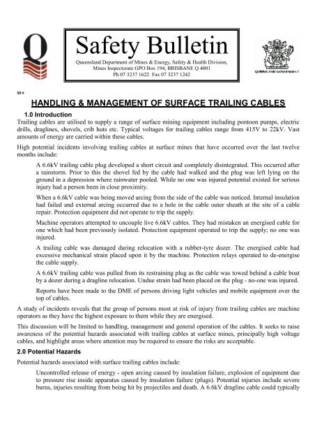
HANDLING & MANAGEMENT OF SURFACE TRAILING CABLES<br />
1.0 Introduction<br />
Trailing cables are utilised to supply a range of surface mining equipment including pontoon pumps, electric<br />
drills, draglines, shovels, crib huts etc. Typical voltages for trailing cables range from 415V to 22kV. Vast<br />
amounts of energy are carried within these cables.<br />
High potential incidents involving trailing cables at surface mines that have occurred over the last twelve<br />
months include:<br />
A 6.6kV trailing cable plug developed a short circuit <strong>and</strong> completely disintegrated. This occurred after<br />
a rainstorm. Prior to this the shovel fed by the cable had walked <strong>and</strong> the plug was left lying on the<br />
ground in a depression where rainwater pooled. While no one was injured potential existed for serious<br />
injury had a person been in close proximity.<br />
When a 6.6kV cable was being moved arcing from the side of the cable was noticed. Internal insulation<br />
had failed <strong>and</strong> external arcing occurred due to a hole in the cable outer sheath at the site of a cable<br />
repair. Protection equipment did not operate to trip the supply.<br />
Machine operators attempted to uncouple live 6.6kV cables. They had mistaken an energised cable for<br />
one which had been previously isolated. Protection equipment operated to trip the supply; no one was<br />
injured.<br />
A trailing cable was damaged during relocation with a rubber-tyre dozer. The energised cable had<br />
excessive mechanical strain placed upon it by the machine. Protection relays operated to de-energise<br />
the cable supply.<br />
A 6.6kV trailing cable was pulled from its restraining plug as the cable was towed behind a cable boat<br />
by a dozer during a dragline relocation. Undue strain had been placed on the plug - no-one was injured.<br />
Reports have been made to the DME of persons driving light vehicles <strong>and</strong> mobile equipment over the<br />
top of cables.<br />
A study of incidents reveals that the group of persons most at risk of injury from trailing cables are machine<br />
operators as they have the highest exposure to them while they are energised.<br />
This discussion will be limited to h<strong>and</strong>ling, management <strong>and</strong> general operation of the cables. It seeks to raise<br />
awareness of the potential hazards associated with trailing cables at surface mines, principally high voltage<br />
cables, <strong>and</strong> highlight areas where attention may be required to ensure the risks are acceptable.<br />
2.0 Potential Hazards<br />
Potential hazards associated with surface trailing cables include:<br />
Uncontrolled release of energy - open arcing caused by insulation failure, explosion of equipment due<br />
to pressure rise inside apparatus caused by insulation failure (plugs). Potential injuries include severe<br />
burns, injuries resulting from being hit by projectiles <strong>and</strong> death. A 6.6kV dragline cable could typically
contain enough energy to light 112,000 40W light bulbs. The pictures below depict a bolted 3-phase<br />
short circuit simulated inside a trailing cable plug <strong>and</strong> facial burns received from an energy release<br />
incident involving high voltage trailing cables.<br />
Indirect contact of a person with electricity - a person receives an electric shock not because they touch<br />
a live conductor, but because they touch a part that has become energised under fault conditions. An<br />
example of this would be a person receives an electric shock after they touch the outer sheath of a<br />
cable. The shock was received because of leakage current to the outer sheath due to insulation failure.<br />
Potential injuries include electric shock, burns <strong>and</strong> death.<br />
Direct contact of a person with electricity - a person touches an energised conductor in the cable. An<br />
example of this would be a person coming into contact with the receptacles inside an energised plug or<br />
touching a conductor inside the cable after it has been damaged. The photographs below depict burn<br />
injuries sustained after direct contact was made with power conductors in a high voltage trailing cable.<br />
Potential injuries include electric shock, burns <strong>and</strong> death.<br />
Fire - the cable catches fire after a fault on the cable. Other equipment or the surrounding environment<br />
subsequently catches fire.<br />
Internal Energy Sources - biomechanical energy; ie. excessive forces placed on the body through<br />
manual tasks. Potential injuries include sprains strains <strong>and</strong> permanent disablement.<br />
3.0 Potential Risks<br />
While the photographs above are graphic, given normal operating conditions, the risks posed to a person by an<br />
energised trailing cable are low, however if the balance is shifted through:<br />
Inappropriate work practice;
Poor maintenance <strong>and</strong> repair st<strong>and</strong>ards;<br />
Inappropriate selection for use; or<br />
Inappropriate operational st<strong>and</strong>ards <strong>and</strong> practice.<br />
- Then the risks may become unacceptable!<br />
Injury, equipment damage or near hits may result, results depicted in the photographs may occur.<br />
Any incidents, damage or injury are all indicators that the risks are not being managed<br />
as they should!<br />
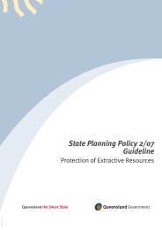
4.0 Typical Surface Trailing Cable Construction<br />
The diagrams below depict a typical high voltage trailing cable used to supply a dragline or shovel.<br />
The design of the cable is such that an earth barrier is placed between the conductors. This is to ensure<br />
that under fault conditions an earth fault will occur first thus ensuring the potential amount of energy<br />
released is reduced compared to a power conductor to power conductor fault (phase to phase). There is<br />
about 10mm distance between the outside of the sheath <strong>and</strong> the power conductor in a 120mm-sq. cable.<br />
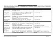
Major components of the cable <strong>and</strong> their function are as follows:<br />
Power Conductor – Copper str<strong>and</strong>ed <strong>and</strong> bundled conductors that deliver the energy to where it is<br />
required to be used. In a 120-mm sq. conductor they would be 15.6mm in diameter.<br />
Power Conductor Insulation – A rubber type insulating compound designed to contain the voltage to<br />
the confines of the power conductor.<br />
Cradle Separator – A cradle that carries the pilot wire at its center. The cradle holds the power<br />
conductors in their desired form <strong>and</strong> constitutes the basis of forming the cable during manufacture.<br />
Earth Metallic Screens – These screens completely surround each power conductor <strong>and</strong> are intended to<br />
carry fault current. They constitute the cable earth.<br />
Pilot Wire – a small conductor at the very center of the cable intended to be used in conjunction with<br />
protection relays to detect cable breakage during operation or prior to operation. The relay used will<br />
cause power to be de-energised in the event of cable breakage or plug separation while the cable is<br />
powered, or prevent power up if plugs are separated or the cable is broken (pilot wire broken).<br />
Sheath – a tough durable, hard wearing material designed to separate the power conductors from the<br />
external environment <strong>and</strong> allow the cable to operate <strong>and</strong> withst<strong>and</strong> physical <strong>and</strong> environmental<br />
conditions, which it was designed to endure.<br />
Semi-conductive tape is used to separate the power conductors from the insulation <strong>and</strong> the insulation<br />
from the earth screens in cables with a higher voltage rating than 3.3kV. In cables with a lower voltage<br />
rating different materials are used for these barriers.
Metallic Screens
Conductor Insulation (About 4mm)<br />
Cable<br />
Conductor<br />
Conductive Rubber<br />
Pilot Cradle<br />
Inner Sheath (Insulation)<br />
Conductor Screen<br />
(Copper)<br />
Outer Sheath<br />
(Insulation)<br />
Strengethening<br />
Mesh (Plastic)<br />
Pilot Conductor<br />
& Pilot Insulation<br />
10 mm<br />
Typical Surface Trailing Cable Construction<br />
(Type 409, 6.6kV, 120 sq. mm Conductors 100mm Diameter)<br />
5.0 Typical Sources of Cable Damage<br />
Typical sources of cable damage include:<br />
Machinery Damage - Machinery driving over cables including dozers, graders, light vehicles <strong>and</strong><br />
equipment being towed across cables e.g. Lighting plants;<br />
Machinery Damage - Machinery striking cables, e.g. Grader blades, trucks striking cables with their<br />
bodies up as they cross beneath bridges;<br />
Machinery Damage – Draglines set shoes down on cable, draglines/drills/shovels propel over cable;<br />
Falling Rocks Strike <strong>and</strong> Damage Cable - Rocks from spoil piles, Falling rocks from buckets being<br />
swung over cables;<br />
Excessive Mechanical Strain – Too much cable attempted to be pulled in one drag, cables get caught<br />
on objects such as rocks <strong>and</strong> tear;<br />
Exceeding Minimum Bending Radius - Cables are only designed to be bent so far (check<br />
manufacturers guidelines for specifics);
Wear Damage to Plugs – Wear to plugs <strong>and</strong> cable chaffing from being towed;<br />
Water Ingress into Plugs - Resulting from damaged plug seals or plugs left on the ground;<br />
Cables Used as Scrapers - When they are being towed rocks <strong>and</strong> dirt collect at the bottom radius bends;<br />
Poor Repair St<strong>and</strong>ards – Repairs fail under service conditions; <strong>and</strong><br />
Cable Sheaths Torn/Punctured – Cable sheaths are torn <strong>and</strong> punctured by sharp objects such as rocks<br />
<strong>and</strong> dragline tub hooks, pin holes from sharp rocks allowing water <strong>and</strong> dirt ingress.<br />
6.0 Recommendations<br />
6.1 Every surface mine where trailing cables are in use should develop, implement <strong>and</strong> maintain a Trailing<br />
Cable Management System addressing the following as a minimum:<br />
Defined selection criteria addressing the application <strong>and</strong> the intended use for trailing cables;<br />
Defined st<strong>and</strong>ards for the operation of trailing cables including:<br />
a) Regular inspection including in-situ visual inspection by machine operators;<br />
b) Regular testing of cables <strong>and</strong> maintenance of test records, definition of cable life cycles for each<br />
cable application <strong>and</strong> definition of measures to monitor <strong>and</strong> measure the life cycle criteria;<br />
c) Route criteria including support measures where applicable, methods <strong>and</strong> heights for crossings,<br />
identification measures for cables, location of cables in proximity to roadways, protection measures<br />
required where it is necessary to swing over the top of cables, vehicle crossings etc.;<br />
d) Methods for relocation of cables <strong>and</strong> provision of adequate equipment to perform the task, e.g.<br />
cable reelers, relocators;<br />
e) Assurance that repairs are performed to appropriate st<strong>and</strong>ards <strong>and</strong> reliable recording of a repair<br />
history for each cable is maintained;<br />
f) Temporary repair measures <strong>and</strong> circumstances under which they can be applied are defined;<br />
g) Methods for manual h<strong>and</strong>ling are defined <strong>and</strong> provision of adequate mechanical lifting aids is<br />
made to eliminate manual h<strong>and</strong>ling sprains <strong>and</strong> strains. Equipment to separate <strong>and</strong> join plugs<br />
should be sought. <strong>No</strong>te that a 1m length of 11/11kV Type 409 cable weighs approximately 15kg;<br />
h) Regular inspection <strong>and</strong> preventive maintenance is performed on cable accessories such as reeling<br />
devices;<br />
i) Regular inspection, maintenance <strong>and</strong> testing is performed on substation earth systems including<br />
earth mats, earth impedance <strong>and</strong> earth connection points, protection relays <strong>and</strong> trip batteries;<br />
j) Provision of unique clear identifiers for each cable <strong>and</strong> trailing cable plug <strong>and</strong> substation outlet;<br />
k) Defined st<strong>and</strong>ards for the circumstances under which trailing cable protection relays can be reset<br />
<strong>and</strong> power re-energised onto a cable where the relay has indicated a fault to be present;<br />
l) Specific regulatory requirements are met;<br />
m) Inspection <strong>and</strong> test procedures for equipment including earths <strong>and</strong> connections, earth<br />
impedance, cables, substations <strong>and</strong> protection equipment after equipment relocation; <strong>and</strong><br />
n) Review <strong>and</strong> audit of the system.<br />
Systems of high voltage switching, access <strong>and</strong> authorisation are developed, implemented monitored<br />
<strong>and</strong> reviewed including the development <strong>and</strong> maintenance of statutory plans.
Direct h<strong>and</strong>ling of energised cables is minimised. All persons should wear insulating gloves covered by<br />
a leather outer when required to directly h<strong>and</strong>le energised trailing cables.<br />
Repair <strong>and</strong> testing of trailing by competent persons to AS 1747. While AS 1747 is principally a<br />
st<strong>and</strong>ard for underground coal mining cables, there is no specific st<strong>and</strong>ard for surface cables. This<br />
st<strong>and</strong>ard does describe appropriate techniques for repair <strong>and</strong> testing of surface cables. It is likely that<br />
this st<strong>and</strong>ard will be revised in the future to include a separate section for repair <strong>and</strong> testing of surface<br />
trailing cables.<br />
Training must be provided where appropriate in the above <strong>and</strong> in trailing cable hazard awareness for all<br />
persons required to work with them or on them. Workers associated with relevant tasks must be consulted in<br />
relation to the development of the systems <strong>and</strong> st<strong>and</strong>ards mentioned above.<br />
Rutherford Cables have kindly provided <strong>and</strong> allowed the use of the above photographs. They have developed<br />
a Cable Hazard Awareness Training Program, which can be delivered at site. Contact Rutherfords or your<br />
local cable repairer or manufacturer for details on any training packages that may be available.<br />
References:<br />
AS 1747 - Reeling, trailing <strong>and</strong> feeder cables used for mining – Repair <strong>and</strong> testing<br />
AS 2802 - Electric cables - Reeling <strong>and</strong> trailing – For mining <strong>and</strong> general use (other than underground coal<br />
mining)<br />
Peter Minahan<br />
Chief Inspector of Mines<br />
SB 6, Date 19/04/2000, Contact: Robert Lewis, Inspector of Mines, 3222 2449