coM.sat IP Basic ISDN Quick Installation Guide
coM.sat IP Basic ISDN Quick Installation Guide
coM.sat IP Basic ISDN Quick Installation Guide

Create successful ePaper yourself
Turn your PDF publications into a flip-book with our unique Google optimized e-Paper software.
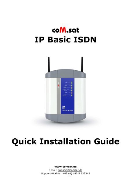
<strong>coM</strong>.<strong>sat</strong><br />
<strong>IP</strong> <strong>Basic</strong> <strong>ISDN</strong><br />
<strong>Quick</strong> <strong>Installation</strong> <strong>Guide</strong><br />
www.com<strong>sat</strong>.de<br />
E-Mail: support@com<strong>sat</strong>.de<br />
Support-Hotline: +49 (0) 180 5 633343
<strong>Quick</strong> <strong>Installation</strong> <strong>Guide</strong> <strong>coM</strong>.<strong>sat</strong> <strong>IP</strong> <strong>Basic</strong> <strong>ISDN</strong><br />
1. Content<br />
1. CONTENT 2<br />
2. LIST OF FIGURES 2<br />
3. DEVICE DESCR<strong>IP</strong>TION 3<br />
4. STARTUP 3<br />
5. CONFIGURATION 5<br />
5.1 ACCESS TO WEB-INTERFACE 5<br />
5.2 MODIFICATION OF THE <strong>IP</strong>-ADDRESS 5<br />
5.2.1 LAN-Port 5<br />
5.2.2 WAN-Port 5<br />
5.3 PIN 6<br />
5.4 ROUTING TABLE 6<br />
6. CONNECTION OF VON <strong>IP</strong>-PHONES 7<br />
6.1 S<strong>IP</strong>-PROXY 7<br />
6.2 S<strong>IP</strong>-TRUNK 9<br />
7. FUNCTION DESCR<strong>IP</strong>TION 10<br />
2. List of figures<br />
FIGURE 1: FRONT SIDE OF THE COM.SAT <strong>IP</strong> BASIC <strong>ISDN</strong> ............................................................. 3<br />
FIGURE 2: BACK SIDE OF THE COM.SAT <strong>IP</strong> BASIC <strong>ISDN</strong> ............................................................... 3<br />
FIGURE 3: CONNECTION OF THE COM.SAT <strong>IP</strong> BASIC <strong>ISDN</strong> ............................................................ 3<br />
FIGURE 4: PIN ............................................................................................................... 6<br />
FIGURE 5: ROUTING-TABLE ................................................................................................ 6<br />
FIGURE 6: CONNECTING EXAMPLE ........................................................................................ 7<br />
FIGURE 7: CONFIGURATION OF THE S<strong>IP</strong>-EXTENSION .................................................................. 8<br />
FIGURE 8: GSM-CONFIGURATION ........................................................................................ 9<br />
FIGURE 9: S<strong>IP</strong>-TRUNK ...................................................................................................... 9<br />
Created: Page: File:<br />
07/2011 2 <strong>Quick</strong>_<strong>Installation</strong>_<strong>Guide</strong>_ Version_1 14_eng.doc<br />
Copyright - DIN 34
<strong>Quick</strong> <strong>Installation</strong> <strong>Guide</strong> <strong>coM</strong>.<strong>sat</strong> <strong>IP</strong> <strong>Basic</strong> <strong>ISDN</strong><br />
3. Device description<br />
Front side view:<br />
1 DC-Socket for the power supply<br />
2 Socket for the NT-Port (RJ-45)<br />
3 Socket for the TE-Port or for<br />
synchroni<strong>sat</strong>ion (RJ-45)<br />
4 Socket for the USB-Interface (USB-B)<br />
5 Switch-key to RESET the unit<br />
6 Socket for LAN-Connection (RJ45)<br />
7 Socket for the WAN-Connection (RJ45)<br />
Back side view:<br />
1 SMA-Connector for the GSM/UMTS-<br />
Channel 2 antenna<br />
2 SIM-Card reader of the GSM/UMTS-<br />
Channel 2<br />
3 SIM-Card reader of the GSM/UMTS-<br />
Channel 1<br />
4 SMA-Connector for the GSM/UMTS-<br />
Channel 1<br />
4. Startup<br />
Figure 1: Front side of the <strong>coM</strong>.<strong>sat</strong> <strong>IP</strong> <strong>Basic</strong><br />
Figure 2: Back side of the <strong>coM</strong>.<strong>sat</strong> <strong>IP</strong> <strong>Basic</strong><br />
• Place the <strong>coM</strong>.<strong>sat</strong> <strong>IP</strong> <strong>Basic</strong> <strong>ISDN</strong> in<br />
appropriate location, where a proper<br />
power supply (mains) is available.<br />
• Screw the antenna(s) on the SMA-<br />
Socket(s).<br />
• To change the <strong>IP</strong>-Address connect the<br />
LAN-Port of the <strong>coM</strong>.<strong>sat</strong> <strong>IP</strong> <strong>Basic</strong> <strong>ISDN</strong> with<br />
PC or Notebook (see chapter 5.2).<br />
• Connect the <strong>ISDN</strong>-line (if available) with<br />
the BRI NT/TE-Port of the <strong>coM</strong>.<strong>sat</strong> <strong>IP</strong> <strong>Basic</strong><br />
<strong>ISDN</strong>.<br />
• Before the SIM card is inserted, please<br />
read the chapter 5.3 on how to deal with Figure 3: Connection of the <strong>coM</strong>.<strong>sat</strong> <strong>IP</strong> <strong>Basic</strong><br />
the SIM card and the PIN.<br />
• Connect the 12V-power supply with the <strong>coM</strong>.<strong>sat</strong> <strong>IP</strong> <strong>Basic</strong> <strong>ISDN</strong>.<br />
• After successful configuration the <strong>coM</strong>.<strong>sat</strong> <strong>IP</strong> <strong>Basic</strong> <strong>ISDN</strong> is operational.<br />
Created: Page: File:<br />
07/2011 3 <strong>Quick</strong>_<strong>Installation</strong>_<strong>Guide</strong>_ Version_1 14_eng.doc<br />
Copyright - DIN 34
<strong>Quick</strong> <strong>Installation</strong> <strong>Guide</strong> <strong>coM</strong>.<strong>sat</strong> <strong>IP</strong> <strong>Basic</strong> <strong>ISDN</strong><br />
Table 1: LED-Indication<br />
LED Status Meaning<br />
LAN Off Port is not connected<br />
Green - on Port is connected and identified<br />
Green - flashing Data transmission<br />
WAN Off Port is not connected<br />
Green - on Port is connected and the router identified<br />
Green - flashing Data transmission<br />
WWAN (3G) Off No internet connection via WWAN<br />
Green - on Internet via 3G<br />
Green - flashing Data transmission via 3G<br />
Yellow - on Internet via GPRS<br />
Yellow - flashing Data transmission via GPRS<br />
Active 1 Off <strong>ISDN</strong> Layer 1 is up<br />
Yellow - on Active call on GSM/UMTS-Channel 1<br />
Yellow - flashing rapidly <strong>ISDN</strong> Layer 1 is down<br />
Yellow – flashing slowly Call setup on channel 2<br />
Network 1 Off No module available<br />
Green - on Module 1 is registered in network<br />
Green - flashing rapidly SIM-Card is not inserted<br />
Green - flashing slowly Waiting for network registration<br />
Power Off Unit off<br />
Green - on Unit is on<br />
Sync Off No Synchroni<strong>sat</strong>ion<br />
Red - on Unit is synchronised with PBX / PSTN (TE-Mode) or PBX (NT-<br />
Mode)<br />
Active 2 Off <strong>ISDN</strong> Layer 2 is up<br />
Yellow - on Active call on GSM/UMTS-Channel 2<br />
Yellow - flashing rapidly <strong>ISDN</strong> Layer 2 is down<br />
Yellow - flashing slowly Call setup on channel 2<br />
Network 2 Off No module available<br />
Green - on Module 2 is registered in network<br />
Green - flashing rapidly SIM-Card is not inserted<br />
Green - flashing slowly Waiting for network registration<br />
Created: Page: File:<br />
07/2011 4 <strong>Quick</strong>_<strong>Installation</strong>_<strong>Guide</strong>_ Version_1 14_eng.doc<br />
Copyright - DIN 34
<strong>Quick</strong> <strong>Installation</strong> <strong>Guide</strong> <strong>coM</strong>.<strong>sat</strong> <strong>IP</strong> <strong>Basic</strong> <strong>ISDN</strong><br />
5. Configuration<br />
5.1 Access to Web-Interface<br />
The user can configure all the parameters of the <strong>coM</strong>.<strong>sat</strong> <strong>IP</strong> <strong>Basic</strong> <strong>ISDN</strong> using the<br />
web interface. It may be necessary, requiring the user to change the port<br />
parameters of the network. This is required if the <strong>coM</strong>.<strong>sat</strong> <strong>IP</strong> <strong>Basic</strong> <strong>ISDN</strong> as part of<br />
a network is established and shall hereafter be accessed on the Web interface to<br />
configure the rest of the system (see chapter 5.2). To access the web interface,<br />
enter the <strong>IP</strong> address of the <strong>coM</strong>.<strong>sat</strong> <strong>IP</strong> <strong>Basic</strong> <strong>ISDN</strong> in the address field of your Web<br />
browser.<br />
Enter the default password 1234 on the login page.<br />
Your login was successful, if listed on the left side of the screen the appropriate<br />
links.<br />
Now all parameters of the <strong>coM</strong>.<strong>sat</strong> <strong>IP</strong> <strong>Basic</strong> <strong>ISDN</strong> can be programmed by clicking<br />
on the appropriate link to the specific property.<br />
After switching on the <strong>coM</strong>.<strong>sat</strong> <strong>IP</strong> <strong>Basic</strong> <strong>ISDN</strong> parameters are programmed with<br />
the given order:<br />
1. Port-Parameter of the network<br />
2. Selection of the region and County code<br />
3. Enter SIM PIN<br />
4. Mobile Port-Parameter<br />
5. Port-Parameter for S<strong>IP</strong><br />
6. Port-Parameter for <strong>ISDN</strong> NT-Port or TE-Port<br />
7. Routing<br />
After successful programming of the <strong>coM</strong>.<strong>sat</strong> <strong>IP</strong> <strong>Basic</strong> <strong>ISDN</strong> the user is able to<br />
make incoming and make outgoing calls.<br />
5.2 Modification of the <strong>IP</strong>-Address<br />
5.2.1 LAN-Port<br />
If the <strong>coM</strong>.<strong>sat</strong> <strong>IP</strong> <strong>Basic</strong> <strong>ISDN</strong> is connected to the LAN-port in the used PC a<br />
static <strong>IP</strong> address is required to be registered within the range of the LANport.<br />
This is necessary because the <strong>coM</strong>.<strong>sat</strong> <strong>IP</strong> <strong>Basic</strong> <strong>ISDN</strong> cannot assign<br />
an <strong>IP</strong> address via DHCP.<br />
The default <strong>IP</strong> address of the LAN-port is: 192.168.2.26.<br />
It is possible to change the <strong>IP</strong> address of the <strong>coM</strong>.<strong>sat</strong> <strong>IP</strong> <strong>Basic</strong> <strong>ISDN</strong> with<br />
the menu item "Network Parameters / Settings".<br />
5.2.2 WAN-Port<br />
The <strong>coM</strong>.<strong>sat</strong> <strong>IP</strong> <strong>Basic</strong> <strong>ISDN</strong> can obtain an <strong>IP</strong> address from the DHCP server<br />
or uses the fixed <strong>IP</strong> address 192.168.1.111<br />
It is possible to change the <strong>IP</strong> address of the <strong>coM</strong>.<strong>sat</strong> <strong>IP</strong> <strong>Basic</strong> <strong>ISDN</strong> with<br />
the menu item "Network Parameters / Settings".<br />
Created: Page: File:<br />
07/2011 5 <strong>Quick</strong>_<strong>Installation</strong>_<strong>Guide</strong>_ Version_1 14_eng.doc<br />
Copyright - DIN 34
<strong>Quick</strong> <strong>Installation</strong> <strong>Guide</strong> <strong>coM</strong>.<strong>sat</strong> <strong>IP</strong> <strong>Basic</strong> <strong>ISDN</strong><br />
5.3 PIN<br />
Figure 4: PIN<br />
The PIN is a security feature on the SIM card, which is used in the device to<br />
protect data stored on the SIM-card from misuse. The PIN should contain at<br />
least four digits and a maximum 8 digits. If the PIN of the SIM card is disabled,<br />
then the edit field remains empty.<br />
If an incorrect PIN is entered, you can see the message 'SIM PIN wrong'.<br />
After three failed attempts or rebooting with the wrong PIN, the SIM-card is<br />
locked. It appears the message 'PUK must be entered'. To unlock the SIM-card,<br />
the PUK must be entered. If the wrong PUK is entered ten times, the card will be<br />
useless. For more information you can see the 'GSM/UMTS Channel Status'.<br />
5.4 Routing table<br />
In the routing table, the user can enter the routing for different destination<br />
numbers. The main table parameters are:<br />
Figure 5: Routing-Table<br />
Destination number: In this field the destination number will be entered. It<br />
can be of a maximum of 24 characters. Valid characters are 0 to 9, *, #, and dot<br />
Created: Page: File:<br />
07/2011 6 <strong>Quick</strong>_<strong>Installation</strong>_<strong>Guide</strong>_ Version_1 14_eng.doc<br />
Copyright - DIN 34
<strong>Quick</strong> <strong>Installation</strong> <strong>Guide</strong> <strong>coM</strong>.<strong>sat</strong> <strong>IP</strong> <strong>Basic</strong> <strong>ISDN</strong><br />
(.). The numbers will be routed trough the selected ports, where port 1 has<br />
higher priority than port 2 and 3, respectively.<br />
6. Connection of <strong>IP</strong>-Phones<br />
Figure 6: Connecting example<br />
6.1 S<strong>IP</strong>-Proxy<br />
To program the S<strong>IP</strong> proxy, the following parameters can be set:<br />
Enable S<strong>IP</strong> Extension: Select the checkbox to enable the S<strong>IP</strong> extension. If this<br />
flag is disabled, you will not able to use this extension.<br />
Name: Enter a name for the S<strong>IP</strong> extension. It is optional.<br />
S<strong>IP</strong> ID: Your S<strong>IP</strong> ID is used to register the S<strong>IP</strong> extension into the Registrer<br />
Server of the <strong>coM</strong>.<strong>sat</strong> <strong>IP</strong> <strong>Basic</strong> <strong>ISDN</strong>. It is the number to which the S<strong>IP</strong> extension<br />
can be called.<br />
Authentication ID: The authentication ID of the <strong>coM</strong>.<strong>sat</strong> <strong>IP</strong> <strong>Basic</strong> <strong>ISDN</strong> is used<br />
to authenticate the S<strong>IP</strong> messages received from the S<strong>IP</strong> extension to the S<strong>IP</strong><br />
proxy.<br />
Authentication Password: The authentication password of the <strong>coM</strong>.<strong>sat</strong> <strong>IP</strong> <strong>Basic</strong><br />
<strong>ISDN</strong> is used to authenticate the S<strong>IP</strong> messages. The password can be up to 24<br />
characters long and contain all ASCII characters.<br />
Created: Page: File:<br />
07/2011 7 <strong>Quick</strong>_<strong>Installation</strong>_<strong>Guide</strong>_ Version_1 14_eng.doc<br />
Copyright - DIN 34
<strong>Quick</strong> <strong>Installation</strong> <strong>Guide</strong> <strong>coM</strong>.<strong>sat</strong> <strong>IP</strong> <strong>Basic</strong> <strong>ISDN</strong><br />
Max calls: This field specifies the number of calls allowed for the S<strong>IP</strong>-extension.<br />
You can select 1 or 2.<br />
DTMF options: This option determines how to send the DTMF signals from S<strong>IP</strong><br />
Extensions to the <strong>coM</strong>.<strong>sat</strong> <strong>IP</strong> <strong>Basic</strong> <strong>ISDN</strong> when a DTMF digit is pressed.<br />
FAX options: This parameter determine how the <strong>coM</strong>.<strong>sat</strong> <strong>IP</strong> <strong>Basic</strong> <strong>ISDN</strong> handled<br />
the fax messages from the S<strong>IP</strong> Extension.<br />
The following is a configuration example how a GSM-connection to a mobile is<br />
setup from a <strong>IP</strong>-phone:<br />
Configuration of S<strong>IP</strong> Extension:<br />
To make calls with an <strong>IP</strong> phone, you should connect it to the LAN-port of the<br />
<strong>coM</strong>.<strong>sat</strong> <strong>IP</strong> <strong>Basic</strong> <strong>ISDN</strong>. Select in the left menu selection 'S<strong>IP</strong> proxy'. You can<br />
configure the parameters in the submenu 'Settings'.<br />
Figure 7: Configuration of the S<strong>IP</strong>-Extension<br />
To allow <strong>IP</strong> telephony, the checkbox enable S<strong>IP</strong> Extension is required to be<br />
activated. Then, it should be enter the Name of the extension to which the <strong>IP</strong><br />
phone is connected. This name appears at the other station as a text in the<br />
display. Next, the S<strong>IP</strong> ID is entered. This is the phone number where the phone<br />
is to be reached. The Authentication ID and the Authentication password<br />
are used to register the S<strong>IP</strong>-extension in the S<strong>IP</strong>-proxy. The ID used to be the<br />
number of the extension. The same settings should be made at the <strong>IP</strong> phone.<br />
Finally, Fixed Route Selection should be selected. With the drop-down menu,<br />
you can choose the route of the destination call is given. In this example a<br />
GSM/UMTS channel has to be selected.<br />
After configure the necessary settings on the <strong>IP</strong> phone, a connection to a mobile<br />
subscriber can be started.<br />
To save the configuration, please press the Submit button<br />
GSM-Configuration:<br />
As an example, the channel 1 of the <strong>coM</strong>.<strong>sat</strong> <strong>IP</strong> <strong>Basic</strong> <strong>ISDN</strong> is used. In the<br />
following web interface, the relevant parameters are displayed:<br />
Created: Page: File:<br />
07/2011 8 <strong>Quick</strong>_<strong>Installation</strong>_<strong>Guide</strong>_ Version_1 14_eng.doc<br />
Copyright - DIN 34
<strong>Quick</strong> <strong>Installation</strong> <strong>Guide</strong> <strong>coM</strong>.<strong>sat</strong> <strong>IP</strong> <strong>Basic</strong> <strong>ISDN</strong><br />
Figure 8: GSM-Configuration<br />
Select in the left menu selection, the main menu, GSM / UMTS Channel 1.<br />
To use the GSM channel 1, it is required to be activated first. Next, if the PIN of<br />
the SIM card is activated, the PIN should be entered.<br />
To save the configuration, please press the Submit button.<br />
6.2 S<strong>IP</strong>-Trunk<br />
The <strong>coM</strong>.<strong>sat</strong> <strong>IP</strong> <strong>Basic</strong> <strong>ISDN</strong> supports up to 4 S<strong>IP</strong> trunks. In every S<strong>IP</strong> trunk, an<br />
Internet Service Provider (ISP) can be entered. The providers may be different.<br />
The following parameters can be set:<br />
Figure 9: S<strong>IP</strong>-Trunk<br />
• S<strong>IP</strong> Trunk activate: To outgoing and incoming calls, the S<strong>IP</strong> trunk needs to<br />
be enabled.<br />
Created: Page: File:<br />
07/2011 9 <strong>Quick</strong>_<strong>Installation</strong>_<strong>Guide</strong>_ Version_1 14_eng.doc<br />
Copyright - DIN 34
<strong>Quick</strong> <strong>Installation</strong> <strong>Guide</strong> <strong>coM</strong>.<strong>sat</strong> <strong>IP</strong> <strong>Basic</strong> <strong>ISDN</strong><br />
• Name: The user can assign a name to the S<strong>IP</strong> trunk. If an outgoing call using<br />
the S<strong>IP</strong> trunk is made, it will appear at the called party's display.<br />
• S<strong>IP</strong>-ID: Enter the S<strong>IP</strong> ID provided by the ISP.<br />
• Address of the Registrar-Server: Enter the ISP provided address of the S<strong>IP</strong><br />
registrar server. This can be an <strong>IP</strong> address or domain.<br />
• Port of the Registrar-Server: Enter the ISP provided the receiving port of<br />
the registar server. The valid range of the port of registrar server is between<br />
1024 to 65535<br />
• Send REGISTER message?: The <strong>coM</strong>.<strong>sat</strong> <strong>IP</strong> <strong>Basic</strong> <strong>ISDN</strong> sends a REGISTER<br />
message to the registar / outbound proxy server.<br />
• Gateway Mode: The <strong>coM</strong>.<strong>sat</strong> <strong>IP</strong> <strong>Basic</strong> V2 will accept incoming calls for S<strong>IP</strong> ID<br />
and Registrar/ Outbound Proxy Server programmed. If the user want the system<br />
to accept the incoming call for any S<strong>IP</strong> ID but only from Registrar/ Outbound<br />
Proxy Server programmed, this flag should be enabled. Thus, when enabled, S<strong>IP</strong><br />
trunk would be used as gateway.<br />
• Allow outgoing calls without registration? : The device does not allow<br />
outgoing calls when the S<strong>IP</strong> trunk is not registered. However, to allow outgoing<br />
calls when the device is not registered in the registrar server, the parameter<br />
should be activated.<br />
• Re-registration timer: The user is required to enter the value for the reregistration<br />
timer. Before expiry of this timer, should the <strong>coM</strong>.<strong>sat</strong> <strong>IP</strong> <strong>Basic</strong> <strong>ISDN</strong><br />
send the registration request to the registration server in order to remain<br />
registered.<br />
• Registration retry timer: This is the period between retries for registration.<br />
The <strong>coM</strong>.<strong>sat</strong> <strong>IP</strong> <strong>Basic</strong> <strong>ISDN</strong> sends the registration request until the S<strong>IP</strong> trunk is<br />
registered with the S<strong>IP</strong> server.<br />
• Maximum calls: The user is required to configure the maximum number of<br />
calls that are allowed on each S<strong>IP</strong> trunk.<br />
7. Function description<br />
The <strong>coM</strong>.<strong>sat</strong> <strong>IP</strong> <strong>Basic</strong> <strong>ISDN</strong> combines the fixed network <strong>ISDN</strong> and <strong>IP</strong> technologies (networks<br />
and terminals) among themselves and with the GSM / UMTS network.<br />
The <strong>coM</strong>.<strong>sat</strong> <strong>IP</strong> <strong>IP</strong> <strong>Basic</strong> <strong>ISDN</strong> is implemented as two UMTS channels.<br />
The use of Sierra Wireless Cellular Engines (MC8792V) not only enable voice communication<br />
but also data transmission and SMS from a PC. The USB interface provides direct access to<br />
the cellular engines.<br />
The main features are:<br />
Created: Page: File:<br />
07/2011 10 <strong>Quick</strong>_<strong>Installation</strong>_<strong>Guide</strong>_ Version_1 14_eng.doc<br />
Copyright - DIN 34
<strong>Quick</strong> <strong>Installation</strong> <strong>Guide</strong> <strong>coM</strong>.<strong>sat</strong> <strong>IP</strong> <strong>Basic</strong> <strong>ISDN</strong><br />
S<strong>IP</strong>-Trunk:<br />
• 10/100 Full Duplex, Autosensing, Ethernet RJ-45 LAN-Port<br />
• 10/100 Full Duplex, Autosensing, Ethernet RJ-45 WAN-Port<br />
• S<strong>IP</strong>v2, <strong>IP</strong>v4 Router<br />
• Supports S<strong>IP</strong>-Proxy<br />
• Session Timer, Record-Routing, authentication<br />
• Compression with different CODECs<br />
• T.38 Fax, G.711 Fax/Modem-Bypass<br />
• G.168 Echo suppression<br />
• Up to 8 parallel voice connections<br />
S<strong>IP</strong>-Proxy:<br />
• 10/100 Full Duplex, Autosensing, Ethernet RJ-45 LAN-Port<br />
• 10/100 Full Duplex, Autosensing, Ethernet RJ-45 WAN-Port<br />
• S<strong>IP</strong>v2, <strong>IP</strong>v4 Router<br />
• Supports S<strong>IP</strong>-Trunk<br />
• Session Timer, Record-Routing, authentication<br />
• Compression with different CODECs<br />
• T.38 Fax, G.711 Fax/Modem-Bypass<br />
• G.168 Echo suppression<br />
• Up to 6 parallel voice connections<br />
WWAN-Connection:<br />
• WWAN UMTS (Standalone / Data backup)<br />
• Fallback routing for data connectivity<br />
<strong>ISDN</strong>-Connection:<br />
• NT, TE in P-P or PMP Mode configurable<br />
• Synchroni<strong>sat</strong>ion port (TE-Port)<br />
• S0-Interface, EDSS1-Protocol, Impedance 100Ω<br />
• S0-Power feed for terminal equipment<br />
• VPBX<br />
GSM/UMTS:<br />
• TS11 Voice in Full Rate and Enhanced Full Rate, DTMF, AMR<br />
• TS12 Emergency function<br />
• TS21 SMS in Text and PDU Mode<br />
• Net-Lock<br />
• SIM-Lock<br />
Hardware interfaces:<br />
• DC-Socket for power supply<br />
• USB Direct access, Transparent Mode and SMS-Server<br />
• RJ45 WAN for Vo<strong>IP</strong>-Service and programming<br />
• RJ45 LAN for Vo<strong>IP</strong>-Services and Programming<br />
• RJ45 NT port for connection to the <strong>ISDN</strong> network according to ISO 8877<br />
• RJ45 TE-Port for Synchroni<strong>sat</strong>ion or connection to the <strong>ISDN</strong> network according<br />
to ISO 8877<br />
• SMA RF connector for the GSM/UMTS antenna<br />
Created: Page: File:<br />
07/2011 11 <strong>Quick</strong>_<strong>Installation</strong>_<strong>Guide</strong>_ Version_1 14_eng.doc<br />
Copyright - DIN 34