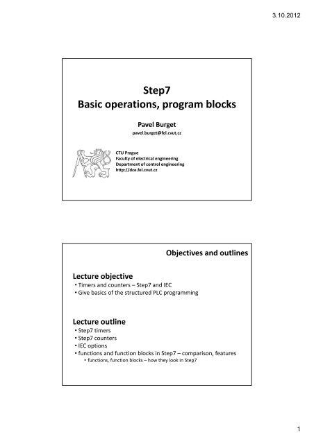
Step7 Basic operations, program blocks - DCE FEL ČVUT v Praze
Step7 Basic operations, program blocks - DCE FEL ČVUT v Praze
Step7 Basic operations, program blocks - DCE FEL ČVUT v Praze

You also want an ePaper? Increase the reach of your titles
YUMPU automatically turns print PDFs into web optimized ePapers that Google loves.
<strong>Step7</strong><br />
<strong>Basic</strong> <strong>operations</strong>, <strong>program</strong> <strong>blocks</strong><br />
Pavel Burget<br />
pavel.burget@fel.cvut.cz<br />
CTU Prague<br />
Faculty of electrical engineering<br />
Department of control engineering<br />
http://dce.fel.cvut.cz<br />
Lecture objective<br />
• Timers and counters –<strong>Step7</strong> and IEC<br />
• Give basics of the structured PLC <strong>program</strong>ming<br />
Objectives and outlines<br />
Lecture outline<br />
• <strong>Step7</strong> timers<br />
• <strong>Step7</strong> counters<br />
• IEC options<br />
• functions and function <strong>blocks</strong> in <strong>Step7</strong> – comparison, features<br />
• functions, function <strong>blocks</strong> –how they look in <strong>Step7</strong><br />
3.10.2012<br />
1
<strong>Step7</strong> timers<br />
Timers<br />
• Internal structures, have their own memory area<br />
• Word access –time value representation<br />
• Bit access – status of the timer (running, stopped)<br />
• Special data type –S5TIME<br />
• Time base<br />
• 10 ms, 100 ms, 1 s, 10 s<br />
• Resolution and range<br />
• E.g. with 10 ms resolution the range is 9 s 990 ms, i.e. 3<br />
BCD digits are used<br />
<strong>Step7</strong> timers overview<br />
3.10.2012<br />
2
Important timers<br />
• Extended Pulse Timer S_PEXT<br />
Important timers<br />
• On‐delay Timer<br />
How can the timer be reset?<br />
<strong>Step7</strong> timers<br />
<strong>Step7</strong> timers<br />
3.10.2012<br />
3
Important timers<br />
• Retentive On‐delay Timer<br />
Can we <strong>program</strong> a S_ODTS<br />
just with S_ODT?<br />
Task for next week.<br />
Important timers<br />
• Off‐delay Timer<br />
Can we <strong>program</strong> a S_OFFDT<br />
just with S_ODT?<br />
Task for next week.<br />
<strong>Step7</strong> timers<br />
<strong>Step7</strong> timers<br />
3.10.2012<br />
4
Connecting timers<br />
• Timer state –the timer can be used in logical <strong>operations</strong><br />
• How do we do a pulse generator?<br />
Counters<br />
• Special memory area –C<br />
• Count value in BCD<br />
• Counter state as a bit<br />
• Counter types<br />
• S_CU –not really useful<br />
• S_CD –much better<br />
• S_CUD<br />
• Be careful not to set the counter with a non‐BCD value<br />
<strong>Step7</strong> timers<br />
<strong>Step7</strong> counters<br />
3.10.2012<br />
5
Counters –S_CU<br />
• I0.0 –count pulses (positive edge)<br />
• I0.2 –with positive edge set the<br />
counter value … not useful<br />
• I0.3 –with positive edge reset the<br />
counter value<br />
• Q4.0 –one if C10 not equal to zero … not useful at all<br />
<strong>Step7</strong> counters<br />
<strong>Step7</strong> counters<br />
Counters –S_CD<br />
• I0.0 –count pulses (positive edge)<br />
• I0.2 –with positive edge set the<br />
counter value<br />
• I0.3 –with positive edge reset the<br />
counter value<br />
• Q4.0 –one if C10 not equal to zero … test for zero to check that<br />
the preset number of pulses has been counted<br />
3.10.2012<br />
6
Counters –S_CUD<br />
• I0.0, I0.1 –count pulses<br />
(positive edge)<br />
• I0.2 –with positive edge set the<br />
counter value<br />
• I0.3 –with positive edge reset the<br />
counter value<br />
• Q4.0 –one if C10 not equal to zero<br />
Organisation <strong>blocks</strong><br />
• OB1, OB100, OB35<br />
• OB121 – synchronous interrupt<br />
• OB82, OB86, OB40 – asynchronous (HW) interrupt<br />
• Block parameters(local stack – L)<br />
<strong>Step7</strong> counters<br />
<strong>Step7</strong>: <strong>program</strong> units<br />
Functions and function <strong>blocks</strong><br />
• Function FC<br />
• in, out, in_out, temp parameters<br />
• Function <strong>blocks</strong> FB<br />
• Always with a dedicated data block (DB)<br />
• Additionally stat parameters (global scope –in the DB address space)<br />
• Instance and global DB –another address space<br />
3.10.2012<br />
7
FB and FC parameters<br />
Simple types<br />
BYTE, WORD, BOOL, etc.<br />
Complex types<br />
ARRAY, TIMER, COUNTER, etc.<br />
BE CAREFUL: when calling <strong>blocks</strong> several times in one scan cycle<br />
Rising edge detection<br />
Timer value<br />
…<br />
• There is one or more data <strong>blocks</strong> (DB) dedicated to each<br />
function block (FB)<br />
– e.g. operation of more devices of the same type with different<br />
parameters<br />
• Multiple‐instance call<br />
– The called FB is a static parameter of the calling function block<br />
– The called FB are under Multiple Instances<br />
– The upper FB must be created with “Allow multiple instances”<br />
– Not so many DBs needed<br />
Multiple-instance<br />
FB<br />
(upper laying)<br />
in …<br />
out …<br />
stat motor1 FB1<br />
stat motor2 FB1<br />
FB10<br />
Function block calls<br />
FB1<br />
FB1<br />
FB1<br />
Function <strong>blocks</strong> in the<br />
static parameters of<br />
the upper FB<br />
3.10.2012<br />
8
• Pointer ‐ 32 bits<br />
• Address registers AR1, AR2<br />
• Indirect addressing<br />
– Memory‐based … T QW[MD12] –write an output word to an address<br />
given by the value of MD12<br />
– Register‐based … T QW[AR1,P#2.0] –write an output word to an<br />
address given by the sum of address register AR1 and 2<br />
• Operations with address registers<br />
– LAR1, LAR2 … load ACCU1 to address register<br />
– LAR1 MD12, LAR1 P#M0.0 … load value to address reg.<br />
– TAR1, TAR2 … transfer value from address register<br />
IMPORTANT<br />
Pointer to address area: P#M0.0 BYTE 20, P#DB1.DBX0.0 BYTE 20<br />
• Area and out‐of‐area addressing<br />
Indirect addressing<br />
A space in the<br />
DB must be<br />
allocated, i.e.<br />
ARRAY<br />
Indirect addressing<br />
– Area … L MW[AR1,P#0.0] –the address space is part of the operand<br />
– Out‐of‐area … L W[AR1,P#0.0] –the address space is given by the<br />
address register<br />
• Examples<br />
– Memory indirect addressing with the area pointer<br />
L P#30.0<br />
T MD12<br />
L MW[MD12]<br />
– Memory indirect addressing with a value –to address counters, timers<br />
and <strong>blocks</strong><br />
L 133<br />
T MW20<br />
OPN DB[MW20]<br />
SE T[MW20]<br />
3.10.2012<br />
9
• Examples<br />
– Register indirect area addressing<br />
OPN DB10<br />
LAR1 P#10.0<br />
L MW[AR1,P#4.0]<br />
A DBX[AR1,P#0.3]<br />
– Register indirect out‐of‐area addressing<br />
LAR1 P#M12.0<br />
L B[AR1,P#2.0]<br />
= [AR1,P#0.7]<br />
What have we said today?<br />
• Timers and counters<br />
• <strong>Basic</strong>s of OBs, FCs and FBs in <strong>Step7</strong><br />
• Data <strong>blocks</strong> (instant, global), examples<br />
• Indirect addressing in <strong>Step7</strong><br />
Indirect addressing<br />
Summary<br />
3.10.2012<br />
10
Thank you for your attention.<br />
Pavel Burget<br />
pavel.burget@fel.cvut.cz<br />
CTU Prague<br />
Faculty of electrical engineering<br />
Department of control engineering<br />
http://dce.fel.cvut.cz<br />
3.10.2012<br />
11