The Static and Dynamic Response Properties of Incidence Vanes ...
The Static and Dynamic Response Properties of Incidence Vanes ...
The Static and Dynamic Response Properties of Incidence Vanes ...

You also want an ePaper? Increase the reach of your titles
YUMPU automatically turns print PDFs into web optimized ePapers that Google loves.
«.<br />
C.P. No. 652<br />
MINISTRY OF AVIATION<br />
AERONAUTICAL RESEARCH COUNCIL<br />
CURRENT PAPERS<br />
<strong>The</strong> <strong>Static</strong> <strong>and</strong> <strong>Dynamic</strong><br />
<strong>Response</strong> <strong>Properties</strong> <strong>of</strong><br />
<strong>Incidence</strong> <strong>Vanes</strong> with Aerodynamic<br />
<strong>and</strong> Internal Viscous Damping<br />
by<br />
W. J. G. Pinsker<br />
LONDON: HER MAJESTY'S STATIONERY OFFICE<br />
1963<br />
PRICE 3s 6d NET<br />
C.P. No. 652
U.D.C. No. 629.13.052.42 : 533.6.013.423 : 533.6.013.6<br />
C.P. No.652<br />
August, 1962<br />
THE STATIC AND DYNAMIC RESPONSE PROPERTIES OF INCIDENCE VANES WITH<br />
AERODYNAMIC AND INTERNAL VISCOUS DAMPING<br />
by<br />
W, J. G-. Pinsker<br />
SUMMARY<br />
<strong>The</strong> various contributions to the static position error <strong>of</strong> practical<br />
incidence vanes are briefly reviewed. <strong>The</strong> dynamic response <strong>of</strong> a windvane<br />
is shown to depend critically on the aerodynamic damping <strong>and</strong> viscous<br />
friction acting on the vane. It is also shown that the vane responds<br />
differently to incidences generated by gusts, aircraft plunging <strong>and</strong> by<br />
aircraft rotary motion. Frequency response formulae <strong>and</strong> graphs are given<br />
to illustrate some typical cases.<br />
Replaces R.A.E. Tech. Note No. Aero 2833 - A.R.C. 24,245-
1 INTRODUCTION<br />
LIST OF CONTENTS<br />
2 THE PRINCIPAL SOURCES OF STATIC AND QUASI-STATIC ERROR 4<br />
3 THE EQUATIONS OF MOTION OF A 7/INBVANE ATTACHED TO<br />
AN AIRCRAFT<br />
LIST OF REFERENCES<br />
ILLUSTRATIONS - Figs. 1-9<br />
DETACHABLE ABSTRACT CARDS LIST OF ILLUSTRATIONS<br />
Page<br />
2.1 <strong>The</strong> isolated vane assembly ^<br />
2.2 <strong>The</strong> effect <strong>of</strong> the support boom on the vane 5<br />
2.3 Position error due to flow induced by aircraft 5<br />
2.4 Kinematic position error<br />
4 FREQUENCY RESPONSE OF WINDVANE TO AIRCRAFT INCIDENCE 9<br />
4.1 Aircraft rotary motion 9<br />
4.2 Aircraft plunging motion or gusts 11<br />
5 NUMERICAL EXAMPLE 12<br />
6 DISCUSSION J[i+<br />
7 CONCLUSIONS 1/ +-<br />
LIST OF SYMBOLS<br />
Vane for measuring incidence in the potential flow field<br />
<strong>of</strong> the vane support 1<br />
From Ref.2. Calibration <strong>of</strong> the sensitivity <strong>of</strong> a cruciform<br />
assembly <strong>of</strong> incidence vanes in a supersonic wind tunnel 2<br />
<strong>The</strong> three components <strong>of</strong> incidence generated on an aircraft in<br />
free flight 3<br />
<strong>The</strong> three components <strong>of</strong> sideslip generated on an aircraft in<br />
free flight k<br />
Definition <strong>of</strong> angles relevant to the response <strong>of</strong> a windvane<br />
to incidence or sideslip 5<br />
Frequency response <strong>of</strong> windvane with internal damping (£.) only<br />
to incidence generated by rotary aircraft motion o<br />
Frequency response <strong>of</strong> windvane with constant internal damping<br />
(£. = 0.5) <strong>and</strong> variable aerodynamic damping to incidence<br />
produced by rotary aircraft motion 7<br />
- 2 -<br />
4<br />
6<br />
1 5<br />
16<br />
Fig,
LIST OF ILLUSTRATIONS (CQNTD.)<br />
Frequency response <strong>of</strong> windvane with constant aerodynamic<br />
damping (£ =0.2) <strong>and</strong> variable internal damping to incidence<br />
a<br />
produced by rotary aircraft motion 8<br />
Frequency response <strong>of</strong> windvane with aerodynamio <strong>and</strong> internal<br />
damping to incidence produced by aircraft plunging motion<br />
or by gusts 9<br />
- 3 -
1 INTRODUCTION<br />
<strong>The</strong> instrument most frequently used to measure the aerodynamic<br />
incidence (angles <strong>of</strong> attack <strong>and</strong> sideslip) <strong>of</strong> aircraft is the windvane.<br />
Designed to align itself with the local airflow, the vane in principle<br />
allows the incidence to be read directly as an angle <strong>and</strong> in this sense it<br />
may be considered as the ideal sensing element for the measurement <strong>of</strong> flow<br />
direction.<br />
In practice, however, this ideal is much more difficult to achieve<br />
than one could suspect from such elementary considerations. Even for<br />
static measurements a number <strong>of</strong> "position errors" will unavoidably distort<br />
the actual readings <strong>of</strong> practical windvanes. Although primarily_concerned<br />
with the dynamic response characteristics <strong>of</strong> incidence vanes, this paper<br />
will first briefly discuss the principal sources <strong>of</strong> static <strong>and</strong> quasi-static<br />
errors.<br />
However even when full allowance is made for these static errors, the<br />
dynamic response <strong>of</strong> the vane may further distort the results, if dynamic<br />
phenomena are to be recorded. <strong>The</strong> vanes used in flight testing are usually<br />
so designed that their natural frequency is an order <strong>of</strong> magnitude greater<br />
than the frequencies <strong>of</strong> the stability modes <strong>of</strong> the aircraft so that these<br />
will be faithfully recorded. This may no longer be true, however, if the<br />
same vane is used to record gusts <strong>of</strong> much higher frequency or perhaps^ if it<br />
is installed on a relatively small flying object, such as a free flight<br />
model with relatively high frequencies <strong>of</strong> its natural responses.<br />
In a recent publication C. J. Friedman has pointed out some<br />
unexpected dynamic response characteristics <strong>of</strong> vanes with internal viscous<br />
damping. In the present investigation both internal damping <strong>and</strong> the<br />
aerodynamic dajnping supplied by the vane itself are considered.<br />
Furthermore a distinction is made between incidence generated by<br />
rotary motion <strong>of</strong> the aircraft (say pitching or yawing), by translatory<br />
aircraft motion (heaving or plunging) <strong>and</strong> by gusts.<br />
2 TH3 PRINCIPAL SOURCES OF STATIC AND QUASI-STATIC ERROR<br />
In this section the principal contributions <strong>of</strong> the aircraft <strong>and</strong> <strong>of</strong> the<br />
vane support to the ?LOcal incidence as sensed in practice by a windvane are<br />
briefly reviewed. Although it is generally realised that such errors are<br />
present, their potential magnitude is <strong>of</strong>ten not fully appreciated. As<br />
virtually all factors contributing to the so called position error normally<br />
are additive in the sense to make the vane over-read, the resulting total<br />
error has been known to reach values <strong>of</strong> almost 100,0 in not unduly careless<br />
installations.<br />
2.1 <strong>The</strong> isolated vane assembly<br />
<strong>The</strong> windvane as understood here is the complete vane assembly which<br />
comprises the actual vane with its mass-balance <strong>and</strong> the support, generally<br />
a cylindrical body, containing the bearings for the vane shaft <strong>and</strong> an<br />
electrical pick-up as illustrated in Fig.1.<br />
When at an incidence, i.e. in a cross flow w = ccV, the potential flow<br />
round the body <strong>of</strong> the instrument will increase the local cross flow velocity<br />
by an amount w, which will be equal to w close to the cylinder <strong>and</strong> decrease<br />
rapidly as the distance from the body increases. This effect can be<br />
reduced by minimising the diameter <strong>of</strong> the instrument body <strong>and</strong> by increasing<br />
the distance <strong>of</strong> the vane from the support. As the magnitude <strong>of</strong> the above<br />
contribution to the position error can be readily determined in a wind tunnel<br />
it would appear unwise to compromise the vane design for this particular<br />
consideration.<br />
- 4 -
<strong>The</strong> effects <strong>of</strong> flow interference induced by the vane support are,<br />
however, more embarrassing in supersonic flow, where the calibration <strong>of</strong> the<br />
vane must be expected to vary with Mach number. In Ref.2, a wind tunnel<br />
calibration is given <strong>of</strong> a supersonic incidence vane in current use. <strong>The</strong><br />
principal results are reproduced in Fig.2. It should be noted that in<br />
this particular case, the vanes were mounted approximately halfway along<br />
the existing noseboom <strong>of</strong> an aircraft, which was relatively bulky <strong>and</strong> therefore<br />
may have contributed strongly to this position error. It has been<br />
suggested that these shortcomings <strong>of</strong> conventional incidence vanes in supersonic<br />
flow could be overcome by using, instead <strong>of</strong> a windvane, a cone freely<br />
pivoted at the head <strong>of</strong> a support sting.<br />
As well as these aerodynamic sources <strong>of</strong> vane error, it is equally<br />
important to consider the effects <strong>of</strong> friction on the vane shaft. Although<br />
vanes are usually free from objectionable friction under laboratory<br />
conditions, flight test results invariably indicate the presence (for<br />
reasons which so far have not been adequately explored) <strong>of</strong> substantial^<br />
friction. It is not uncommon to observe, apparently because <strong>of</strong> friction,<br />
lags in the response <strong>of</strong> vanes <strong>of</strong> up to 0.05 sec, clearly a prohibitive<br />
amount, even if relatively slow aircraft responses are recorded. It has<br />
frequently been found that static measurements fail to show an equivalent<br />
amount <strong>of</strong> friotion-caused hysteresis. A possible explanation <strong>of</strong> this<br />
apparent inconsistency is as follows:<br />
In steady conditions the level <strong>of</strong> vibrations in the aircraft may permit<br />
the vane to overcome the friction in jerks <strong>and</strong> finally reach the correct<br />
position. This same behaviour (also e.g. observed in the trailing motion<br />
<strong>of</strong> a rudder with circuit friction) would convert a basically solid type<br />
friction force into an apparent viscous type in dynamic measurements.<br />
Although great improvements are being made at present to reduce or<br />
eliminate potentiometer friction, it must be emphasised that such refinements<br />
may be wasted if no corresponding attention is paid to bearing friction<br />
caused by aerodynamic loads.<br />
2 • 2 <strong>The</strong> effects <strong>of</strong> the support boom on the vane<br />
Another source <strong>of</strong> "position error" which is frequently overlooked is<br />
the aeroelastic distortion <strong>of</strong> the boom supporting the actual vane. At<br />
high indicated speeds this phenomenon has been estimated to contribute<br />
alone 20> to the overall position error. More complex still is the position<br />
if the inertia <strong>of</strong> the boom + vane assembly is considered as well so that we<br />
have to treat it as an oscillatory system. Further one must remember that<br />
the aircraft itself is an elastic structure, so that the vane will measure<br />
the incidence <strong>of</strong> the particular part <strong>of</strong> the airframe, to which it is attached<br />
<strong>and</strong> not strictly the quantity that is normally described as "incidence" or<br />
"sideslip".<br />
2,3 Position error due to flow induced by aircraft<br />
Whereas it should be possible to predict or calibrate on the ground the<br />
contributions to the position error discussed so far, the effect most<br />
commonly understood a3 the aerodynamic position error may be much more difficult<br />
to estimate. <strong>The</strong>re are essentially three methods available to account<br />
for this position error. <strong>The</strong>y are listed below in order <strong>of</strong> increasing<br />
reliability:<br />
(i) theoretical estimate <strong>of</strong> the induced flow field in the vicinity<br />
<strong>of</strong> the vane location<br />
- 5 -
(ii) flow survey on a wind tunnel model <strong>of</strong> the aircraft<br />
(iii) static calibration in flight.<br />
It is obvious that the latter technique can give by far the most accurate<br />
calibration not only <strong>of</strong> the aircraft induced position error but <strong>of</strong> all the<br />
errors discussed so far.<br />
2 • **• Kinematic position error<br />
As windvanes cannot normally be mounted at the C.G. <strong>of</strong> the aircraft they<br />
sense in addition to the incidence proper (which is normally referred to the<br />
C.G. <strong>of</strong> the aircraft) flow components generated by the rotary motion <strong>of</strong> the<br />
aircraft. A full table <strong>of</strong> all the possible corrections that may be applicable<br />
to a particular vane - location is given in the A.G-.A.R.D. Flight Test manual<br />
Vol.11 Chapter 11:4(e). For instance an angle <strong>of</strong> attack vane, if mounted at<br />
a distance x feet ahead <strong>of</strong> the C.G. within the plane <strong>of</strong> symmetry, records<br />
pitching q as an incremental incidence,<br />
Aa = -f , (D<br />
similarly, it senses rate <strong>of</strong> roll p if mounted outside the plane <strong>of</strong> symmetry,<br />
say y feet out on the starboard wing, as:<br />
^ = f . (2)<br />
<strong>The</strong>se kinematic corrections can be fully eliminated from a flight record<br />
if the relevant aircraft rates <strong>of</strong> rotation are measured.<br />
3 THE EQUATIONS OF MOTION OF A WINDVANE ATTACHED TO AN AIRCRAFT<br />
In the following analysis we shall be investigating the dynamic response<br />
<strong>of</strong> a windvane to the various components <strong>of</strong> aerodynamic incidence which the aircraft<br />
experiences in flight. For simplicity <strong>of</strong> analysis the vane is assumed<br />
here to be free from position errors although it would be easy to take the<br />
static position error contributions into account when interpreting actual.<br />
dynamic flight tests. May it suffice here to indicate that:<br />
(i) aerodynamic position errors induced by the instrument body, <strong>and</strong> by<br />
the aircraft, <strong>and</strong> the kinematic position errors discussed in<br />
Section 2.4, are equivalent to what shall now be termed incidence<br />
generated by translatory motion (a^ or B )<br />
Y X<br />
(ii) quasi-steady position errors due to boom <strong>and</strong> aircraft elasticity<br />
are equivalent to incidences generated by aircraft rotary motion<br />
(aQ or p+).<br />
Restricting the discussion now to the idealised case <strong>of</strong> a vane subject<br />
to no position error, <strong>and</strong> taking first angle <strong>of</strong> attack the vane senses incidences<br />
which may be generated in flight (Fig.3) by three distinct phenomena:<br />
(i) angular rotation <strong>of</strong> the aircraft to give an incidence equivalent<br />
to angle <strong>of</strong> pitch<br />
ae = 6 (3)<br />
- 6 -
(ii) translatory motion <strong>of</strong> the aircraft z to give<br />
where y i s ^he angle <strong>of</strong> climb<br />
ar = - Y = - ? (4)<br />
(iii) gust with components normal to the surface <strong>of</strong> the vane, i.e.<br />
a . Is<br />
g V '<br />
<strong>The</strong> total incidence sensed by the vane in the longitudinal plane is<br />
therefore<br />
<strong>and</strong><br />
(5)<br />
a = ag + a + a (0<br />
In the lateral plane as illustrated in Fig.4 we get similarly:<br />
s<br />
\<br />
p s<br />
e<br />
2 +<br />
» v * £<br />
v J<br />
= Q, + 0 +<br />
<strong>The</strong>se two cases are obviously identical <strong>and</strong> any results obtained for the<br />
longitudinal case can be applied to the lateral motion if we substitute<br />
-3 for a e<br />
•0 for a<br />
X Y<br />
•3 for a .<br />
K S g<br />
- 7 -<br />
•<br />
V<br />
><br />
(7)<br />
(8)<br />
(9)
Considering now the longitudinal case only, the response <strong>of</strong> a windvane<br />
with mass balance exposed to the airflow as shown in Fig.1 is described by<br />
the equation (Fig.5)<br />
where 6 = deflection <strong>of</strong> vane<br />
l(aQ+6) - da(ae4) - di - k(y-ag+6) = 0 (10)<br />
I ss i TT . vane inertia about pivot<br />
o «<br />
dlvl<br />
d - —— , aerodynamic vane damping<br />
a db<br />
m.<br />
d. = —-r=- . internal vane damping<br />
1 35<br />
k = -^r , weathercock stability <strong>of</strong> vane,<br />
do<br />
As the incidence due to aircraft translation a^ <strong>and</strong> due to gust ag are<br />
additive, they may be combined into the plunging incidence:<br />
Equation (10) can be nondimensionalised to read<br />
az = aY+ag ' 00<br />
5e+S + 2^un(oe+S) + 2Siwn6 + wn (
where W = weight <strong>of</strong> vane<br />
S = area <strong>of</strong> vane surface<br />
dM,/d8<br />
I. = -82.1 -2L--(£\ rr^- (15)<br />
v.e 2 Wf' a i°<br />
1<br />
£ s distance <strong>of</strong> centre <strong>of</strong> pressure <strong>of</strong> the vane from pivot<br />
a. = lift slope <strong>of</strong> vane surface<br />
i = inertia radius <strong>of</strong> vane<br />
o<br />
o" = relative density.<br />
<strong>The</strong> natural frequency <strong>of</strong> the vane wn is proportional to equivalent<br />
air speed. It can be shown that this is also true over a wide range <strong>of</strong><br />
flight conditions <strong>of</strong> the high frequency modes <strong>of</strong> the aircraft oscillation<br />
in yaw <strong>and</strong> in pitch. Consequently a windvane will tend to work at a<br />
fixed frequency ratio when recording these aircraft modes.<br />
<strong>The</strong> inherent aerodynamic damping when expressed as a damping ratio<br />
<strong>of</strong> the vane is independent <strong>of</strong> speed but reduces with increasing altitude.<br />
<strong>The</strong> relative damping provided by a mechanical damper is inversely<br />
proportional to equivalent air speed.<br />
4 FREQUENCY RESPONSE OF WINDVANS TO AIRCRAFT INCIDENCE<br />
It has been shown that the aerodynamic incidence, which a windvane<br />
senses, can be separated into two kinematically distinct components. aQ<br />
or (0.) results from angular displacement <strong>of</strong> the aircraft <strong>and</strong> «z or (0y)<br />
can be generated by either aircraft plunging or by normal gusts or by a<br />
combination <strong>of</strong> both. <strong>The</strong> response <strong>of</strong> the vane <strong>of</strong> these two different<br />
types <strong>of</strong> input differs, so they are treated separately.<br />
4.1 Aircraft rotary motion<br />
Assuming a to be zero in equation (12) <strong>and</strong> assuming<br />
the response <strong>of</strong> the vane 6 to cu can be obtained by substituting<br />
o<br />
iwt<br />
(16)<br />
6 = 5o e iwt (17)<br />
into equation (12). This gives the frequency response expression,<br />
- 3 -
1 +<br />
fe<br />
4£ a (£ a +£•) 1 y i w<br />
n<br />
- I —H<br />
2<br />
d - («/«n) 2 )<br />
1 +<br />
n \<br />
:-J<br />
1 -<br />
1 • fe<br />
<strong>The</strong> modulus <strong>of</strong> this complex expression gives the amplitude ratio,<br />
«a^a + ^ '<br />
1 +<br />
r- - (t<br />
1 +<br />
n<br />
7<br />
2^2<br />
2*. S-<br />
1 w n<br />
> "M<br />
2(£ +£.) w/u<br />
v ^a ^i y ' n<br />
1 -<br />
<strong>and</strong> the phase angle between 5 <strong>and</strong> aQ is given by<br />
tan e<br />
o--»ct,<br />
n<br />
*.l5-<br />
't<br />
1 -<br />
4£ ^°a(£ +£•) ,<br />
v a °i 7 \u<br />
1 - :-J<br />
2\2<br />
With aerodynamic damping only, £. = 0 <strong>and</strong> equations (19) <strong>and</strong> (20) reduce to<br />
<strong>and</strong><br />
1 +<br />
n<br />
(18)<br />
(19)<br />
(20)<br />
= 1.0 (21)<br />
<strong>The</strong> windvane without mechanical damping therefore indicates the<br />
correct value <strong>of</strong> cu over the full frequency range.<br />
- 10 -<br />
(22)
For the other extreme with instrument damping only (£a = 0) equations<br />
(19) <strong>and</strong> (20) have been computed for the range <strong>of</strong> the parameters 0
2(£Q+£.) f<br />
tan ec . =<br />
'6->a "<br />
— .<br />
/ \2<br />
(27)<br />
z<br />
1 - •<br />
Equations (25)-(27) are identical to those for a conventional second order<br />
system if (£ +£.) = £ is taken as the total damping. <strong>The</strong> corresponding<br />
response diagrams are given in Fig,9,<br />
5 NUMERICAL SXAI/iPLE<br />
As a typical example, the incidence vane used at present for high speed<br />
testing at the R.A.E. is considered. <strong>The</strong> approximate principal dimensions<br />
for this instrument are:<br />
2<br />
5 = 0,007 ft vane area<br />
W = 0.035 lb weight <strong>of</strong> vane assembly<br />
i /
If the above vane is used to record these aircraft modes it will<br />
work at a relative frequency <strong>of</strong><br />
for the lateral case, <strong>and</strong> at<br />
n<br />
15.6<br />
1500<br />
1<br />
100<br />
w "15.6 1_<br />
OJ„ a 750 * 50<br />
n<br />
for the pitching case. Obviously for this application the windvane<br />
defined above measures without any noticeable dynamic error.<br />
However if the same vane is used to measure gusts on an aircraft<br />
flying at a given speed the maximum frequencies that can be measured are<br />
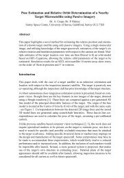
limited if the maximum permissible error is specified. Ignoring<br />
position errors, the limiting relative frequencies can be obtained from<br />
Fig. 9 <strong>and</strong> then,<br />
maximum frequency, f max<br />
V.<br />
[sec" -1 ] .<br />
15.6<br />
A<br />
For a vane with negligible damping (^a+^i) = 0, at two aircraft speeds<br />
V. = 310 ft/sec <strong>and</strong> 620 ft/sec, these maximum frequencies are, for given<br />
error limits,<br />
Maximum error<br />
5£<br />
Wo<br />
2Cf£<br />
(t)<br />
0.225<br />
0.3<br />
0.41<br />
V. =310 ft/sec<br />
1<br />
maximum<br />
frequency<br />
c.p.s.<br />
4.45<br />
6.0<br />
8.2<br />
V. =620 ft/sec<br />
maximum<br />
frequency<br />
c.p.s.<br />
8.90<br />
12.0<br />
16.4<br />
In particular at low speeds the dynamic response <strong>of</strong> the vane can therefore<br />
significantly limit the range <strong>of</strong> data it will reliably record.<br />
Another application where the performance <strong>of</strong> this vane may be<br />
expected to be unsatisfactory is the measurement <strong>of</strong> the stability modes<br />
<strong>of</strong> a small scale free flight model. Assuming that the aircraft<br />
mentioned previously is scaled down by a factor <strong>of</strong> 20, the frequencies<br />
<strong>of</strong> the corresponding modes <strong>of</strong> motion <strong>of</strong> the model will be increased by<br />
the same factor at a given speed. <strong>The</strong> vane will then be working within<br />
the range <strong>of</strong> relative frequency —5 < *~~ < \ • Fi S« 9 shows that the<br />
component <strong>of</strong> the flight incidence resulting from the translatory potion<br />
<strong>of</strong> the model will be measured with an error <strong>of</strong> between 20$ <strong>and</strong> 4%, if<br />
one assumes negligible vane damping.<br />
It is interesting to note that a windvane used exclusively for the<br />
recording <strong>of</strong> gusts (when phase is not important) could be made satisfactory<br />
by providing mechanical damping to approximately 0.7 <strong>of</strong> critical.<br />
- 13 -
However at the same time the pitching response <strong>of</strong> the aircraft (see Fig, 6)<br />
would be grossly misread by this vane at relative frequencies significantly<br />
greater than — =0.<br />
n<br />
For incidence measurements on small scale models for the same reason<br />
internal damping would be most detrimental to the faithful recording <strong>of</strong> the<br />
stability modes.<br />
6 DISCUSSION<br />
It has been shown that there are many potential sources contributing<br />
to the overall static "position error" <strong>of</strong> an incidence vane installed on an<br />
aircraft <strong>and</strong> that care has to be taken to reduce these to an acceptable<br />
magnitude. <strong>The</strong> best method to account for these effects is a flight<br />
calibration, which is strongly advised if vanes are to be used for accurate<br />
me a sur erne n t s,<br />
Friction within the vane assembly is another potential source <strong>of</strong><br />
inaccuracy which will mainly affect the recording <strong>of</strong> dynamic phenomena.<br />
<strong>The</strong> dynamic response characteristics <strong>of</strong> incidence vanes are affected<br />
by aerodynamic damping (as generated by the vane itself) <strong>and</strong> by mechanical<br />
damping, which will normally be generated by friction <strong>and</strong> in certain cases<br />
may be deliberately introduced into the vane by a viscous damper.<br />
<strong>Vanes</strong> have been shown to respond in a distinctly different manner to<br />
the two kinematic components into which the quantity normally summarised as<br />
incidence (or sideslip) can be separated. One is generated by rotary<br />
aircraft motion, i.e. by pitching or yawing, the other by translatory<br />
motion (i.e. plunging or heaving) <strong>of</strong> the aircraft.<br />
In general dynamic effects will diminish when the natural frequency<br />
<strong>of</strong> the vane, w , is increased in relation to the frequencies <strong>of</strong> the flight<br />
phenomena to be recorded. This fundamental consideration suggests that one<br />
should choose vanes with small dimensions <strong>and</strong> inertias. When vanes are<br />
used on relatively snail aircraft such as small scale free flight models it<br />
may become necessary to consider the frequency response <strong>of</strong> the vane more<br />
seriously. This is <strong>of</strong> course also true even for measurements on larger<br />
aircraft if there is significant friction in the vane.<br />
When considering the use <strong>of</strong> incidence vanes for the measurement <strong>of</strong><br />
gusts it is interesting to observe that for this purpose the addition <strong>of</strong><br />
internal viscous damping may be advantageous. In fact in common with<br />
general instrument practice, approximately 0.7 <strong>of</strong> critical damping would<br />
appear to give the most truthful recording <strong>of</strong> amplitudes for gust frequencies<br />
up to the natural frequency <strong>of</strong> the vane. At the same time for frequencies<br />
near w the corresponding pitching response <strong>of</strong> the aircraft (see Fig.8) will<br />
be largely ignored by such a vane.<br />
This example <strong>of</strong> a possible unorthodox application <strong>of</strong> the results <strong>of</strong><br />
the present study shows that vane design, assembly <strong>and</strong> operation must be<br />
carefully tailored to the particular purpose <strong>of</strong> the investigation.<br />
7 CONCLUSIONS<br />
<strong>The</strong> conventional incidence vane has been shown to respond differently<br />
to the various aircraft modes <strong>and</strong> to gusts. Whereas for the measurement <strong>of</strong><br />
aircraft stability a vane without damping is more suitable, for the<br />
- 14 -
measurement <strong>of</strong> gusts, a vane with a high degree <strong>of</strong> internal damping may<br />
have advantages. However, care ha3 to be taken to minimise, <strong>and</strong><br />
calibrate incidence vanes for, the various contributions to the position<br />
error, <strong>and</strong> also to reduce friction before the potential accuracy <strong>of</strong> this<br />
type <strong>of</strong> instrument is realised.<br />
aC L<br />
a, = —— lift slope <strong>of</strong> vane block<br />
1 da<br />
9M<br />
d s -—7 damping <strong>of</strong> vane<br />
d6<br />
LIST 0? SYMBOLS<br />
i = |vj g inertia radius <strong>of</strong> vane assembly<br />
I inertia <strong>of</strong> vane assembly<br />
AM<br />
k - -rr restoring moment <strong>of</strong> vane<br />
dO<br />
I distance <strong>of</strong> centre <strong>of</strong> pressure <strong>of</strong> vane from pivot<br />
M moment about vane pivot<br />
5 area <strong>of</strong> vane blade<br />
V airspeed<br />
V. indicated airspeed<br />
W weight <strong>of</strong> vane assembly<br />
a incidence<br />
0 angle <strong>of</strong> sideslip<br />
6 deflection <strong>of</strong> vane<br />
Y aircraft angle <strong>of</strong> climb<br />
X aircraft flight path azimuth angle<br />
£ damping ratio<br />
w rad/sec frequency<br />
w rad/sec natural frequency <strong>of</strong> vane<br />
G aircraft attitude<br />
i{f aircraft yaw<br />
- 15 -
LIST OF RETICENCES<br />
No. Author Title, etc.<br />
1 Friedman, G-.J. Frequency response analysis <strong>of</strong> the vane type<br />
angle <strong>of</strong> attack transducer.<br />
Aero/Space Engineering. 18(3) March. 1959,<br />
69-75.<br />
2 Dee, F, Wind tunnel calibration <strong>of</strong> incidence vanes for<br />
Mabey, G-. use on the Fairey E.R.103.<br />
A.R.C. 23,611. September, 1961.<br />
W.2078.C.P.652.K3 - Printed in Engl<strong>and</strong><br />
- 16
t<br />
BALANCE WEI&HT<br />
ORIGINAL FLI&<br />
a (b) =cxg (b)+ ar (t) + a (b)<br />
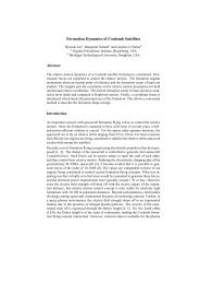
FIG. 3. THE THREE COMPONENTS OF INCIDENCE<br />
GENERATED ON AN AIRCRAFT IN FREE FLIGHT<br />
(ONLY POSITIVE ANGLES ARE SHOWN)<br />
/0(b)-/(?Y(t)+/?y(t>f/39(t;<br />
FIG. 4. THE THREE COMPONENTS OF SIDESLIP<br />
GENERATED ON AN AIRCRAFT IN FREE FLIGHT<br />
(ONLY POSITIVE ANGLES ARE SHOWN)
FIG. 5. DEFINITIONS OF ANGLES RELEVANT TO THE<br />
RESPONSE OF A WIND VANE TO INCIDENCE OR SIDESLIP
-100<br />
20<br />
FIG 6. FREQUENCY RESPONSE OF WINDVANE WITH<br />
INTERNAL DAMPING (£J ONLY TO INCIDENCE<br />
LEAD<br />
LAG<br />
GENERATED BY ROTARY AIRCRAFT MOTION ((*0) OR (/3^)
0<br />
a ei<br />
0-5<br />
"5-*a<br />
-100<br />
\\r<br />
\Xg<br />
AMPLITUDE RATIO<br />
.^y<br />
°3^7<br />
0-5 1-0 W<br />
U).<br />
71<br />
FIG.7. FREOUENCY RESPONSE OF WINDVANE WITH<br />
CONSTANT INTERNAL DAM PING (^=0-5) AND VARIABLE<br />
AERODYNAMIC DAMPING TO INCIDENCE PRODUCED<br />
BY ROTARY AIRCRAFT MOTION<br />
i<br />
2-0<br />
2-0<br />
LEAD<br />
LAG
-100<br />
Si-o<br />
cu.<br />
n<br />
FIG. 8. FREOUENCY RESPONSE OF WINDVANE WITH<br />
CONSTANT AERODYNAMIC DAMPING (fQ = 0-2) AND<br />
2-0<br />
VARIABLE INTERNAL DAMPING TO INCIDENCE<br />
PRODUCED BY ROTARY AIRCRAFT MOTION<br />
LEAD<br />
LAG
sJ *J<br />
3-0<br />
2-5<br />
2-0<br />
IKl<br />
1-5<br />
1*0<br />
0*5<br />
5-* a.<br />
-9tf<br />
-180<br />
0-5<br />
0-5<br />
O J/<br />
I<br />
V) 1/<br />
^I 0 . 2 ,<br />
// °' 3<br />
#<<br />
1 ° >t,<br />
v/s—^**<br />
^0-6<br />
*^\0-8^<br />
°i<br />
1<br />
AMPLITUDE RATIO<br />
.0<br />
it-<br />
\ \l<br />
\1<br />
\ \ %<br />
\ \ |<br />
1-0<br />
(?)<br />
71<br />
0 1-5<br />
PHASE ANGLE<br />
FIG.9. FREQUENCY RESPONSE OF WINDVANE WITH AERODYNAMIC<br />
AND INTERNAL DAMPING, TO INCIDENCE PRODUCED BY<br />
AIRCRAFT PLUNGING MOTION a OR BY GUSTS<br />
2-0<br />
20
A,R,C. C.P, No,652<br />
629.13.052.42:<br />
533.6.013.423:<br />
533.6.013.6<br />
THE STATIC AND DYNAMIC RESPONSE PROPERTIES OF INCIDENCE<br />
VANES WITH AERODYNAMIC AND INTERNAL VISCOUS DAMPING. Pinsker, W.J.G.<br />
Aug. 1962.<br />
<strong>The</strong> various contributions to the static position error <strong>of</strong> practical<br />
incidence vanes are briefly reviewed. <strong>The</strong> dynamic response <strong>of</strong> a windvane<br />
is shown to depend critically on the aerodynamic damping <strong>and</strong> viscous<br />
friction acting on the vane. It is also shown that the vane responds<br />
differently to incidences generated by gusts, aircraft plunging <strong>and</strong> by<br />
aircraft rotary motion. Frequency response formulae <strong>and</strong> graphs are given<br />
to illustrate some typical cases.<br />
A.R,C, C,P, No.652<br />
629.13.052.42:<br />
533.6.013.423:<br />
533.6.013.6<br />
THE STATIC AND DYNAMIC RESPONSE PROPERTIES OF INCIDENCE<br />
VANES WITH AERODYNAMIC AND INTERNAL VISCOUS DAMPING. Pinsker, W.J.G.<br />
Aug. 1962.<br />
<strong>The</strong> various contributions to the static position error <strong>of</strong> practical<br />
incidence vanes are briefly reviewed. <strong>The</strong> dynamic response <strong>of</strong> a windvane<br />
is shown to depend critically on the aerodynamic damping <strong>and</strong> viscous<br />
friction acting on the vane. It is also shown that the vane responds<br />
differently to incidences generated by gusts, aircraft plunging <strong>and</strong> by<br />
aircraft rotary motion. Frequency response formulae <strong>and</strong> graphs are given<br />
to illustrate some typical cases.<br />
A,R,C, C.P, No,652<br />
629.13.052.42:<br />
533.6.013.423:<br />
533.6.013.6<br />
THE STATIC AND DYNAMIC RESPONSE PROPERTIES OF INCIDENCE<br />
VANES WITH AERODYNAMIC AND INTERNAL VISCOUS DAMPING. Pinsker, W.J.G.<br />
Aug. 1962.<br />
<strong>The</strong> various contributions to the static position error <strong>of</strong> practical<br />
incidence vanes are briefly reviewed. <strong>The</strong> dynamic response <strong>of</strong> a windvane<br />
is shown to depend critically on the aerodynamic damping <strong>and</strong> viscous<br />
friction acting on the vane. It is also shown that the vane responds<br />
differently to incidences generated by gusts, aircraft plunging <strong>and</strong> by<br />
aircraft rotary motion. Frequency response formulae <strong>and</strong> graphs are given<br />
to illustrate some typical cases.<br />
A,R,C, C,P, No, 652<br />
629.13.052.42:<br />
533.6.013.423:<br />
533.6.013.6<br />
THE STATIC AND DYNAMIC RESPONSE PROPERTIES OF INCIDENCE<br />
VANES WITH AERODYNAMIC AND INTERNAL VISCOUS DAMPING. Pinsker, W.J.G.<br />
Aug. 1962.<br />
<strong>The</strong> various contributions to the static position error <strong>of</strong> practical<br />
incidence vanes are briefly reviewed. <strong>The</strong> dynamic response <strong>of</strong> a windvane<br />
is shown to depend critically on the aerodyne: ic damping <strong>and</strong> viscous<br />
friction acting on the vane. It is also she. .1 that the vane responds<br />
differently to incidences generated by gusts, aircraft plunging <strong>and</strong> by<br />
aircraft rotary motion. Frequency response 1ormulae <strong>and</strong> graphs are given<br />
to illustrate some typical cases.
© Crown Copyright 1963<br />
Published by<br />
HER MAJESTY'S STATIONERY OFFICE<br />
To be purchased from<br />
York House, Kingsway, London w.c.2<br />
423 Oxford Street, London w.l<br />
13A Castle Street, Edinburgh 2<br />
109 St. Mary Street, Cardiff<br />
39 King Street, Manchester 2<br />
50 Fairfax Street, Bristol 1<br />
35 Smallbrook, Ringway, Birmingham<br />
80 Chichester Street, Belfast 1<br />
or through any bookseller<br />
Printed In Engl<strong>and</strong><br />
C.P. No. 652<br />
S.O. CODE No. 23-9013-52<br />
C.P. No. 652