Memorandum - Low-Energy Muons
Memorandum - Low-Energy Muons
Memorandum - Low-Energy Muons

Create successful ePaper yourself
Turn your PDF publications into a flip-book with our unique Google optimized e-Paper software.
PAUL SCHERRER INSTITUT<br />
Date:<br />
From:<br />
Phone:<br />
Room:<br />
E-mail:<br />
29/May/2008<br />
T. Prokscha<br />
4275<br />
WLGA / U119<br />
thomas.prokscha@psi.ch<br />
<strong>Memorandum</strong><br />
To:<br />
cc:<br />
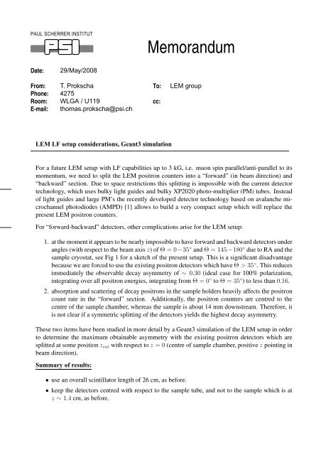
LEM LF setup considerations, Geant3 simulation<br />
LEM group<br />
For a future LEM setup with LF capabilities up to 3 kG, i.e. muon spin parallel/anti-parallel to its<br />
momentum, we need to split the LEM positron counters into a “forward” (in beam direction) and<br />
“backward” section. Due to space restrictions this splitting is impossible with the current detector<br />
technology, which uses bulky light guides and bulky XP2020 photo-multiplier (PM) tubes. Instead<br />
of light guides and large PM’s the recently developed detector technology based on avalanche microchannel<br />
photodiodes (AMPD) [1] allows to build a very compact setup which will replace the<br />
present LEM positron counters.<br />
For “forward-backward” detectors, other complications arise for the LEM setup:<br />
1. at the moment it appears to be nearly impossible to have forward and backward detectors under<br />
angles (with respect to the beam axis z) of Θ = 0−35 ◦ and Θ = 145−180 ◦ due to RA and the<br />
sample cryostat, see Fig 1 for a sketch of the present setup. This is a significant disadvantage<br />
because we are forced to use the existing positron detectors which have Θ > 35 ◦ . This reduces<br />
immediately the observable decay asymmetry of ∼ 0.30 (ideal case for 100% polarization,<br />
integrating over all positron energies, integrating from Θ = 0 ◦ to Θ = 35 ◦ ) to less than 0.16.<br />
2. absorption and scattering of decay positrons in the sample holders heavily affects the positron<br />
count rate in the “forward” section. Additionally, the positron counters are centred to the<br />
centre of the sample chamber, whereas the sample is about 14 mm downstream. Therefore, it<br />
is not clear if a symmetric splitting of the detectors yields the highest decay asymmetry.<br />
These two items have been studied in more detail by a Geant3 simulation of the LEM setup in order<br />
to determine the maximum obtainable asymmetry with the existing positron detectors which are<br />
splitted at some position zcut with respect to z = 0 (centre of sample chamber, positive z pointing in<br />
beam direction).<br />
Summary of results:<br />
• use an overall scintillator length of 26 cm, as before.<br />
• keep the detectors centred with respect to the sample tube, and not to the sample which is at<br />
z ∼ 1.4 cm, as before.
• cut the detectors at zcut = −1 cm for maximum asymmetry; i.e. the “backward” detectors<br />
(upstream side, towards RA) have a length of 12 cm, and the ”forward“ detectors (downstream<br />
side, towards cryostat) have a lenght of 14 cm.<br />
• the maximum asymmetry A max<br />
LF is ≤ 0.12 for either positive, P + , or negative polarization,<br />
P − , where P + means muon spin parallel to z (beam direction). Since the beam polarization<br />
is about 90% the asymmetries decrease correspondingly.<br />
• with “small” (4.2 cm) sample plates asymmetry does not change, but event rate increases<br />
between 12% and 15%.<br />
• we can “increase the asymmetry by a factor of two” by determining the difference A +−<br />
LF of<br />
asymmetries A +<br />
LF<br />
A −<br />
LF<br />
and A−<br />
LF for both P + and P − : A +−<br />
LF<br />
= A+<br />
LF<br />
− A−<br />
LF<br />
. Note, that A+<br />
LF and<br />
contain an “offset” asymmetry for zero polarization due to the geometry of the detectors<br />
and positron absorbtion in the sample plates. This offset cancels in A +−<br />
LF .<br />
• a spin-rotator for LEM for ±90 ◦ spin rotations seems to be feasible up to 20 keV muon energy:<br />
a 300 mm long device with max. fields of ±360 G and ±210 kV/m would meet the demands.<br />
At 15 keV the fields are lower by 15/20. Such a device can’t be placed in the moderator<br />
chamber, but it could be installed in the trigger chamber: it must be positioned in front of TD<br />
(TD blows up phase space too much) and it requires a redesign of the TD chamber, with the<br />
trigger moved closer to the sample, thus improving the time resolution. The spin-rotator also<br />
acts as a very efficient proton/ion separator to get rid off ions from the moderator before hitting<br />
TD.<br />
Details:<br />
Input parameter for Geant3 simulation:<br />
• z points along beam axis/direction.<br />
• z = 0 is the centre of the sample tube; sample is at z ∼ 1.4 cm.<br />
• start 10 5 decay positrons at sample position, homogeneous beam spot with 2 cm diameter.<br />
• annular positron detectors.<br />
• secondary particle generation (γ, electrons) enabled, minimum energy 10 keV.<br />
• for a valid hit: require energy deposition > 0.2 MeV in inner and outer scintillator.<br />
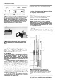
Figure 2 shows the distribution of positron detector hits along the beam axis (z) for unpolarized<br />
muons for a) only the sample tube and RA are present, and b) the sample cryostat with Al plates is<br />
in place.<br />
Figure 3 shows the forward/backward asymmetry for longitudinal polarizations of -100,0,+100% as<br />
a function of cut position zcut where the detectors are splitted into the forward section and backward<br />
section. z = 0 is the centre of the sample chamber, and the positron counters are centred at this<br />
position.<br />
The observable asymmetry as a function of zcut for the case that one measures either with positive or<br />
PAUL SCHERRER INSTITUTE, CH-5232 Villigen PSI, Switzerland Page 2
negative polarization is obtained by subtracting the asymmetry A 0 LF<br />
respective asymmetries A +<br />
LF<br />
obtained at zcut = −1 cm.<br />
and A−<br />
LF<br />
for zero polarization from the<br />
. The result is shown in Fig. 4. The maximum asymmetry is<br />
− A−<br />
LF allows to get rid off<br />
the A0 LF “offset”, and to “double” the observable asymmetry. This is shown in Fig. 5. The same is<br />
shown in Fig. 6 for positron counters centred at the sample position (z = 1.4 cm). In this case, the<br />
observable asymmetry is about 7% reduced. The results of the simulation are summarized in more<br />
detail in the following. The “N0’s” are the number of detected hits in the detectors for a minimum<br />
energy deposition of 0.2 MeV. The initial number of muons was 105 .<br />
If measurements with both polarities are possible, the difference A +<br />
LF<br />
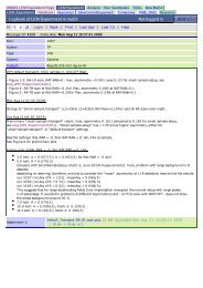
z_sample l_det z_det N0-Pol0 N0-negPol N0-posPol z_cut Pol0-Asym negPol-Asym posPol-Asym<br />
1.4 26 0.0 49929 53421 46508 -5.0 0.547 0.479 0.633<br />
1.4 26 0.0 49929 53421 46508 -4.0 0.434 0.349 0.533<br />
1.4 26 0.0 49929 53421 46508 -3.0 0.297 0.197 0.403<br />
1.4 26 0.0 49929 53421 46508 -2.0 0.137 0.026 0.253<br />
1.4 26 0.0 49929 53421 46508 -1.0 -0.053 -0.167 0.071<br />
1.4 26 0.0 49929 53421 46508 0.0 -0.268 -0.379 -0.154<br />
1.4 26 0.0 49929 53421 46508 1.0 -0.503 -0.600 -0.400<br />
1.4 26 0.0 49929 53421 46508 2.0 -0.649 -0.735 -0.567<br />
#<br />
# shift detectors to sample position<br />
#<br />
1.4 26 1.4 48759 51891 45791 -5.0 0.587 0.534 0.666<br />
1.4 26 1.4 48759 51891 45791 -4.0 0.474 0.402 0.563<br />
1.4 26 1.4 48759 51891 45791 -3.0 0.333 0.244 0.434<br />
1.4 26 1.4 48759 51891 45791 -2.0 0.168 0.068 0.283<br />
1.4 26 1.4 48759 51891 45791 -1.0 -0.020 -0.131 0.093<br />
1.4 26 1.4 48759 51891 45791 0.0 -0.240 -0.350 -0.134<br />
1.4 26 1.4 48759 51891 45791 1.0 -0.481 -0.578 -0.385<br />
1.4 26 1.4 48759 51891 45791 2.0 -0.635 -0.718 -0.552<br />
#<br />
# shift detectors to sample position, 28.8cm length instead of 26cm<br />
#<br />
1.4 28.8 1.4 50151 53690 46556 -5.0 0.548 0.484 0.633<br />
1.4 28.8 1.4 50151 53690 46556 -4.0 0.436 0.350 0.532<br />
1.4 28.8 1.4 50151 53690 46556 -3.0 0.299 0.198 0.409<br />
1.4 28.8 1.4 50151 53690 46556 -2.0 0.141 0.032 0.257<br />
1.4 28.8 1.4 50151 53690 46556 -1.0 -0.044 -0.157 0.071<br />
1.4 28.8 1.4 50151 53690 46556 0.0 -0.257 -0.371 -0.147<br />
1.4 28.8 1.4 50151 53690 46556 1.0 -0.491 -0.598 -0.396<br />
1.4 28.8 1.4 50151 53690 46556 2.0 -0.644 -0.728 -0.559<br />
#--------------------------------------<br />
# small sample plates<br />
#--------------------------------------<br />
1.4 26 0.0 56795 59853 53863 -5.0 0.602 0.536 0.684<br />
1.4 26 0.0 56795 59853 53863 -4.0 0.505 0.423 0.596<br />
1.4 26 0.0 56795 59853 53863 -3.0 0.386 0.288 0.490<br />
1.4 26 0.0 56795 59853 53863 -2.0 0.248 0.136 0.359<br />
1.4 26 0.0 56795 59853 53863 -1.0 0.086 -0.030 0.205<br />
1.4 26 0.0 56795 59853 53863 0.0 -0.097 -0.219 0.014<br />
1.4 26 0.0 56795 59853 53863 1.0 -0.308 -0.424 -0.201<br />
1.4 26 0.0 56795 59853 53863 2.0 -0.459 -0.561 -0.361<br />
#<br />
# shift detectors to sample position<br />
#<br />
1.4 26 1.4 55837 58052 53144 -5.0 0.643 0.580 0.716<br />
1.4 26 1.4 55837 58052 53144 -4.0 0.536 0.464 0.628<br />
1.4 26 1.4 55837 58052 53144 -3.0 0.413 0.323 0.521<br />
1.4 26 1.4 55837 58052 53144 -2.0 0.267 0.167 0.390<br />
1.4 26 1.4 55837 58052 53144 -1.0 0.101 -0.006 0.234<br />
1.4 26 1.4 55837 58052 53144 0.0 -0.089 -0.201 0.045<br />
PAUL SCHERRER INSTITUTE, CH-5232 Villigen PSI, Switzerland Page 3
1.4 26 1.4 55837 58052 53144 1.0 -0.305 -0.410 -0.176<br />
1.4 26 1.4 55837 58052 53144 2.0 -0.457 -0.551 -0.342<br />
#<br />
# shift detectors to sample position, 28.8cm length instead of 26cm<br />
#<br />
1.4 28.8 1.4 57079 59880 54019 -5.0 0.605 0.541 0.687<br />
1.4 28.8 1.4 57079 59880 54019 -4.0 0.508 0.425 0.600<br />
1.4 28.8 1.4 57079 59880 54019 -3.0 0.391 0.293 0.494<br />
1.4 28.8 1.4 57079 59880 54019 -2.0 0.250 0.141 0.367<br />
1.4 28.8 1.4 57079 59880 54019 -1.0 0.090 -0.028 0.211<br />
1.4 28.8 1.4 57079 59880 54019 0.0 -0.094 -0.218 0.025<br />
1.4 28.8 1.4 57079 59880 54019 1.0 -0.302 -0.418 -0.191<br />
1.4 28.8 1.4 57079 59880 54019 2.0 -0.456 -0.557 -0.348<br />
Spin rotator considerations:<br />
If we want to rotate the spin on an effective length leff = 300 mm by 90 ◦ we have to do the following<br />
estimates:<br />
• velocity of a 20 keV µ + : v = 2E/m = 5.83 mm/ns. The drift time for 300 mm is then<br />
51.5 ns.<br />
• spin precession by 90 ◦ in 51.5 ns means 360 ◦ in 206 ns which corresponds to νµ = 4.85 MHz.<br />
This requires a field of about 360 G.<br />
• Which E-field is needed? In order to keep the µ + on a straight path we must have v = E/B<br />
from which we get E = v · B ∼ 210 kV/m.<br />
• for 15 cm gap electrodes this means 31.5 kV potential difference to be applied. For 10 cm gap,<br />
this reduces to 21 kV.<br />
• For 15 keV transport energy, the values above scale down by 15/20 = 0.866.<br />
Check the deflection angles (see [2]): the deflection angles φE and φB of the E- and B-field are given<br />
by:<br />
φE e · leff · E<br />
p · v<br />
φB e · leff · B<br />
p<br />
= ηE · E<br />
β · p<br />
(1)<br />
= ηB · B<br />
, (2)<br />
p<br />
where e is the charge, v the velocity, p the momentum, and β = v/c. For leff = 300 mm we get<br />
ηE = 0.3 mrad MeV/c<br />
kV/m<br />
ηB = 9.0 mrad MeV/c<br />
. (4)<br />
G<br />
Now, consider the deflection angles for 20 keV µ + (β = 0.01946, p = 2.056 MeV/c) and 20-keV<br />
protons (β = 0.00653, p = 6.126 MeV/c). For the muon we obtain φE = φB 1575 mrad which is<br />
about 90 ◦ as it should. For the protons we get<br />
φE(proton) = 1574.6 mrad (5)<br />
φB(proton) = 528.9 mrad, (6)<br />
PAUL SCHERRER INSTITUTE, CH-5232 Villigen PSI, Switzerland Page 4<br />
(3)
yielding a net deflection of φE − φB 1050 mrad ( 60 ◦ ). This should allow to efficiently get rid<br />
of protons before hitting TD.<br />
References:<br />
[1] R. Scheuermann, A. Stoykov, D. Renker, Z. Sadygov, R. Mehtieva, A. Dovlatov, V. Zhuk,<br />
Development of scintillation detectors based on avalanche microchannel photodiodes, Nucl.<br />
Instr. Meth. A571, 317 (2007).<br />
[2] T. Prokscha, The new µE4 separator, PSI internal memorandum, 2007,<br />
http://lmu.web.psi.ch/lem/newmue4/mue4 separator/.<br />
PAUL SCHERRER INSTITUTE, CH-5232 Villigen PSI, Switzerland Page 5
Figure 1: Setup of LEM sample chamber with present positron detectors. The length of the sample<br />
tube is 324 ± 0.1 mm.<br />
PAUL SCHERRER INSTITUTE, CH-5232 Villigen PSI, Switzerland Page 6
1400<br />
1200<br />
1000<br />
800<br />
600<br />
400<br />
200<br />
0<br />
1600<br />
1400<br />
1200<br />
1000<br />
800<br />
600<br />
400<br />
200<br />
0<br />
/scratch/prokscha/geant/geant_lemsr_4002.nt<br />
a) only sample tube<br />
GEANT 4002 z (cm), dE_sci and dE_sco gt 0.2 MeV<br />
/scratch/prokscha/geant/geant_lemsr_4002.nt<br />
ID<br />
b) sample cryostat<br />
ID<br />
Entries<br />
Mean<br />
RMS<br />
-10 -5 0 5 10<br />
Entries<br />
Mean<br />
RMS<br />
-10 -5 0 5 10<br />
GEANT 4001 z (cm), dE_sci and dE_sco gt 0.2 MeV<br />
2008/05/28 13.51<br />
4002<br />
74276<br />
0.9732<br />
5.484<br />
4001<br />
49929<br />
-1.702<br />
Figure 2: Geant3 simulation: z position of positron detector hits for unpolarized muons decaying at<br />
rest at z = 1.4 cm. a) only sample tube and RA mounted, b) sample cryostat with Al plates installed.<br />
The “bump” at about z = −7 cm is due to particles scattering in the RA.<br />
PAUL SCHERRER INSTITUTE, CH-5232 Villigen PSI, Switzerland Page 7<br />
4.462
Forw/Backward Asymmetry<br />
geant3_LEM_LF.rootData.smallSample==0&&Data.l_det
posPolAsym - zeroPolAsym<br />
negPolFBAsym - zeroPolAsym<br />
geant3_LEM_LF.rootData.smallSample==0&&Data.l_det==26&&z_det==0, posPolFBAsym<br />
0.12<br />
0.11<br />
0.1<br />
0.09<br />
0.08<br />
-0.07<br />
-0.08<br />
-0.09<br />
-0.1<br />
-0.11<br />
-5 -4 -3 -2 -1 0 1 2<br />
z_cut (cm)<br />
geant3_LEM_LF.rootData.smallSample==0&&Data.l_det==26&&z_det==0, negPolFBAsym<br />
sample at z = 1.4 cm<br />
detectors (26cm ) centred at z = 0 cm<br />
-5 -4 -3 -2 -1 0 1 2<br />
z_cut (cm)<br />
Tue May 20 18:47:20 2008<br />
Figure 4: Geant3 simulation: observable decay asymmetries A +<br />
LF − A0LF , top, and A−<br />
LF − A0LF ,<br />
bottom, as a function of zcut.<br />
PAUL SCHERRER INSTITUTE, CH-5232 Villigen PSI, Switzerland Page 9
posPolFBAsym - negPolFBAsym<br />
geant3_LEM_LF.rootData.smallSample==0&&Data.l_det==26&&z_det==0, posPolFBAsym<br />
0.24<br />
0.22<br />
0.2<br />
0.18<br />
0.16<br />
Tue May 20 18:52:31 2008<br />
-5 -4 -3 -2 -1 0 1 2<br />
z_cut (cm)<br />
Figure 5: Geant3 simulation: observable decay asymmetries A +<br />
LF − A−<br />
LF<br />
posPolAsym - negPolAsym<br />
geant3_LEM_LF.rootData.smallSample==0&&Data.l_det==26&&z_det>1.3, DiffPosNeg<br />
0.22<br />
0.2<br />
0.18<br />
0.16<br />
0.14<br />
Wed May 21 16:56:27 2008<br />
sample at z = 1.4 cm<br />
detectors (26cm) centred at z = 1.4 cm<br />
-5 -4 -3 -2 -1 0 1 2<br />
z_cut (cm)<br />
Figure 6: Geant3 simulation: observable decay asymmetries A +<br />
LF<br />
− A−<br />
LF<br />
as a function of zcut.<br />
as a function of zcut.<br />
Detectors are centred at the sample position at z = 1.4 cm. For 28.8-cm long detectors, centred at<br />
1.4 cm, the asymmetry is ∼ 0.228, about 0.01 less than in Fig. 5.<br />
PAUL SCHERRER INSTITUTE, CH-5232 Villigen PSI, Switzerland Page 10