A 50-Gb/s IP Router - Networks and Mobile Systems
A 50-Gb/s IP Router - Networks and Mobile Systems
A 50-Gb/s IP Router - Networks and Mobile Systems

You also want an ePaper? Increase the reach of your titles
YUMPU automatically turns print PDFs into web optimized ePapers that Google loves.
IEEE/ACM TRANSACTIONS ON NETWORKING, VOL. 6. NO. 3, JUNE 1998 231<br />
A <strong>50</strong>-<strong>Gb</strong>/s <strong>IP</strong> <strong>Router</strong><br />
Craig Partridge, Senior Member, IEEE, Philip P. Carvey, Member, IEEE, Ed Burgess, Isidro Castineyra, Tom Clarke,<br />
Lise Graham, Michael Hathaway, Phil Herman, Allen King, Steve Kohalmi, Tracy Ma, John Mcallen,<br />
Trevor Mendez, Walter C. Milliken, Member, IEEE, Ronald Pettyjohn, Member, IEEE,<br />
John Rokosz, Member, IEEE, Joshua Seeger, Michael Sollins, Steve Starch,<br />
Benjamin Tober, Gregory D. Troxel, David Waitzman, <strong>and</strong> Scott Winterble<br />
Abstract-Aggressive research on gigabit-per-second networks<br />
has led to dramatic improvements in network transmission<br />
speeds. One result of these improvements has been to put<br />
pressure on router technology to keep pace. This paper describes<br />
a router, nearly completed, which is more than fast enough to<br />
keep up with the latest transmission technologies. The router<br />
has a backplane speed of <strong>50</strong> Gh/s <strong>and</strong> can forward tens of<br />
millions of packets per second.<br />
Index Terms-Data communications, internetworking, packet<br />
switching, routing.<br />
T<br />
I. INTRODUCTION<br />
RANSMISSION link b<strong>and</strong>widths keep improving, at<br />
a seemingly inexorable rate, as the result of research<br />
in transmission technology [26]. Simultaneously, exp<strong>and</strong>ing<br />
network usage is creating an ever-increasing dem<strong>and</strong> that can<br />
only be served by these higher b<strong>and</strong>width links. (In 1996<br />
<strong>and</strong> 1997, Internet service providers generally reported that<br />
the number of customers was at least doubling annually <strong>and</strong><br />
that per-customer b<strong>and</strong>width usage was also growing, in some<br />
cases by 15% per month.)<br />
Unfortunately, transmission links alone do not make a<br />
network. To achieve an overall improvement in networking<br />
performance, other components such as host adapters, operating<br />
systems, switches, multiplexors, <strong>and</strong> routers also need to<br />
get faster. <strong>Router</strong>s have often been seen as one of the lagging<br />
technologies. The goal of the work described here is to show<br />
that routers can keep pace with the other technologies <strong>and</strong> are<br />
Manuscript received February 20, 1997; revised July 22, 1997; approved<br />
by IEEE/ACM TRANSACTIONS ON NETWORKING Editor G. Parulkar. This work<br />
was supported by the Defense Advanced Research Projects Agency (DARPA).<br />
C. Partridge is with BBN Technologies, Cambridge, MA 02138 USA, <strong>and</strong><br />
with Stanford University, Stanford, CA 94305 USA (e-mail: craig@bbn.com).<br />
P. P. Carvey, T. Clarke, <strong>and</strong> A. King were with BBN Technologies,<br />
Cambridge, MA 02138 USA. They are now with Avici <strong>Systems</strong>, Inc.,<br />
Chelmsford, MA 01824 USA (e-mail: phil@avici.com; tclarke@avici.com;<br />
allen@avici.com).<br />
E. Burgess, I. Castineyra, L. Graham, M. Hathaway, P. Herman, S.<br />
Kohalmi, T. Ma, J. Mcallen, W. C. Milliken, J. Rokosz, J. Seeger, M.<br />
Sollins, S. Starch, B. Tober, G. D. Troxel, <strong>and</strong> S. Winterble are with BBN<br />
Technologies, Cambridge, MA 02138 USA (e-mail: skohalmi@bbn.com;<br />
milliken@bbn.com; jseeger@bbn.com; sstorch@bbn.com; tober@bbn.com).<br />
T. Mendez was with BBN Technologies, Cambridge, MA 02138 USA. He<br />
is now with Cisco <strong>Systems</strong>, Cambridge, MA 02138 USA.<br />
R. Pettyjohn was with BBN Technologies, Cambridge, MA 02138 USA.<br />
He is now with<br />
ronp@argon.com).<br />
Argon <strong>Networks</strong>, Littleton, MA 01460 USA (e-mail:<br />
D. Waitzman was with BBN Technologies, Cambridge, MA 02138 USA.<br />
He is now with D. E. Shaw <strong>and</strong> Company, L.P., Cambridge, MA 02139 USA.<br />
Publisher Item Identifier S 1063-6692(98)04174-O.<br />
1063-6692/98$10.00 0 1998 IEEE<br />
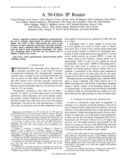
fully capable of driving the new generation of links (OC-48c<br />
at 2.4 <strong>Gb</strong>/s).<br />
A multigigabit router (a router capable of moving data<br />
at several gigabits per second or faster) needs to achieve<br />
three goals. First, it needs to have enough internal b<strong>and</strong>width<br />
to move packets between its interfaces at multigigabit rates.<br />
Second, it needs enough packet processing power to forward<br />
several million packets per second (MPPS). A good rule<br />
of thumb, based on the Internet’s average packet size of<br />
approximately 1000 b, is that for every gigabit per second<br />
of b<strong>and</strong>width, a router needs 1 MPPS of forwarding power.’<br />
Third, the router needs to conform to a set of protocol<br />
st<strong>and</strong>ards. For Internet protocol version 4 (<strong>IP</strong>v4), this set of<br />
st<strong>and</strong>ards is summarized in the Internet router requirements<br />
[3]. Our router achieves all three goals (but for one minor<br />
variance from the <strong>IP</strong>v4 router requirements, discussed below).<br />
This paper presents our multigigabit router, called the MGR,<br />
which is nearly completed. This router achieves up to 32<br />
MPPS forwarding rates with <strong>50</strong> <strong>Gb</strong>/s of full-duplex backplane<br />
capacity.* About a quarter of the backplane capacity is lost<br />
to overhead traffic, so the packet rate <strong>and</strong> effective b<strong>and</strong>width<br />
are balanced. Both rate <strong>and</strong> b<strong>and</strong>width are roughly two to ten<br />
times faster than the high-performance routers available today.<br />
II. OVERVIEW OF THE ROUTER ARCHITECTURE<br />
A router is a deceptively simple piece of equipment. At<br />
minimum, it is a collection of network interfaces, some sort of<br />
bus or connection fabric connecting those interfaces, <strong>and</strong> some<br />
software or logic that determines how to route packets among<br />
those interfaces. Within that simple description, however, lies a<br />
number of complexities. (As an illustration of the complexities,<br />
consider the fact that the Internet Engineering Task Force’s<br />
Requirements for <strong>IP</strong> Version 4 <strong>Router</strong>s [3] is 175 pages long<br />
<strong>and</strong> cites over 100 related references <strong>and</strong> st<strong>and</strong>ards.) In this<br />
section we present an overview of the MGR design <strong>and</strong> point<br />
out its major <strong>and</strong> minor innovations. After this section, the rest<br />
of the paper discusses the details of each module.<br />
‘See [25]. Some experts argue for more or less packet processing power.<br />
Those arguing for more power note that a TCP/<strong>IP</strong> datagram containing an<br />
ACK but no data is 320 b long. Link-layer headers typically increase this<br />
to approximately 400 b. So if a router were to h<strong>and</strong>le only minimum-sized<br />
packets, a gigabit would represent 2.5 million packets. On the other side,<br />
network operators have noted a recent shift in the average packet size to<br />
nearly 2000 b. If this change is not a fluke, then a gigabit would represent<br />
only 0.5 million packets.<br />
*Recently some companies have taken to summing switch b<strong>and</strong>width in<br />
<strong>and</strong> out of the switch; in that case this router is a IOO-<strong>Gb</strong>/s router.
238 IEEE/ACM TRANSACTIONS ON NETWORKING, VOL. 6, NO. 3, JUNE 1998<br />
Fig. I. MGR outline.<br />
A. Design Summary<br />
I<br />
Packets<br />
Headera<br />
A simplified outline of the MGR design is shown in Fig. 1,<br />
which illustrates the data processing path for a stream of<br />
packets entering from the line card on the left <strong>and</strong> exiting<br />
from the line card on the right.<br />
The MGR consists of multiple line cards (each supporting<br />
one or more network interfaces) <strong>and</strong> forwarding engine cards,<br />
all plugged into a high-speed switch. When a packet arrives<br />
at a line card, its header is removed <strong>and</strong> passed through the<br />
switch to a forwarding engine. (The remainder of the packet<br />
remains on the inbound line card). The forwarding engine<br />
reads the header to determine how to forward the packet <strong>and</strong><br />
then updates the header <strong>and</strong> sends the updated header <strong>and</strong><br />
its forwarding instructions back to the inbound line card. The<br />
inbound line card integrates the new header with the rest of<br />
the packet <strong>and</strong> sends the entire packet to the outbound line<br />
card for transmission.<br />
Not shown in Fig. 1 but an important piece of the MGR<br />
is a control processor, called the network processor, that<br />
provides basic management functions such as link up/down<br />
management <strong>and</strong> generation of forwarding engine routing<br />
tables for the router.<br />
B. Mujor Innovations<br />
There are five novel elements of this design. This section<br />
briefly presents the innovations. More detailed discussions,<br />
when needed, can be found in the sections following.<br />
First, each forwarding engine has a complete set of the<br />
routing tables. Historically, routers have kept a central master<br />
routing table <strong>and</strong> the satellite processors each keep only a<br />
modest cache of recently used routes. If a route was not in a<br />
satellite processor’s cache, it would request the relevant route<br />
from the central table. At high speeds, the central table can<br />
easily become a bottleneck because the cost of retrieving a<br />
I<br />
Switch<br />
Llne Card<br />
Packets<br />
Output<br />
route from the central table is many times (as much as 1000<br />
times) more expensive than actually processing the packet<br />
header. So the solution is to push the routing tables down<br />
into each forwarding engine. Since the forwarding engines<br />
only require a summary of the data in the route (in particular,<br />
next hop information), their copies of the routing table, called<br />
forwurding tables, can be very small (as little as 100 kB for<br />
about <strong>50</strong>k routes [61).<br />
Second, the design uses a switched backplane. Until very<br />
recently, the st<strong>and</strong>ard router used a shared bus rather than<br />
a switched backplane. However, to go fast, one really needs<br />
the parallelism of a switch. Our particular switch was custom<br />
designed to meet the needs of an Internet protocol (TP) router.<br />
Third, the design places forwarding engines on boards<br />
distinct from line cards. Historically, forwarding processors<br />
have been placed on the line cards. We chose to separate them<br />
for several reasons. One reason was expediency; we were not<br />
sure if we had enough board real estate to fit both forwarding<br />
engine functionality <strong>and</strong> line card functions on the target<br />
card size. Another set of reasons involves flexibility. There<br />
are well-known industry cases of router designers crippling<br />
their routers by putting too weak a processor on the line<br />
card, <strong>and</strong> effectively throttling the line card’s interfaces to<br />
the processor’s speed. Rather than risk this mistake, we built<br />
the fastest forwarding engine we could <strong>and</strong> allowed as many<br />
(or few) interfaces as is appropriate to share the use of the<br />
forwarding engine. This decision had the additional benefit of<br />
making support for virtual private networks very simple-we<br />
can dedicate a forwarding engine to each virtual network <strong>and</strong><br />
ensure that packets never cross (<strong>and</strong> risk confusion) in the<br />
forwarding path.<br />
Placing forwarding engines on separate cards led to a fourth<br />
innovation. Because the forwarding engines are separate from<br />
the line cards, they may receive packets from line cards that
PARTRIDGE et al.: <strong>50</strong>-<strong>Gb</strong>h <strong>IP</strong> ROUTER 239<br />
use different link layers, At the same time, correct <strong>IP</strong> for-<br />
warding requires some information from the link-layer packet<br />
header (largely used for consistency checking). However, for<br />
fast forwarding, one would prefer that the forwarding engines<br />
not have to have code to recognize, parse, <strong>and</strong> load a diversity<br />
of different link-layer headers (each of which may have a<br />
different length). Our solution was to require all line cards to<br />
support the ability to translate their local link-layer headers to<br />
<strong>and</strong> from an abstract link-layer header format, which contained<br />
the information required for <strong>IP</strong> forwarding.<br />
The fifth innovation was to include quality of service (QoS)<br />
processing in the router. We wanted to demonstrate that it was<br />
possible to build a cutting edge router that included line-speed<br />
QoS. We chose to split the QoS function. The forwarding<br />
engine simply classifies packets, by assigning a packet to a<br />
flow, based on the information in the packet header. The actual<br />
scheduling of the packet is done by the outbound line card, in<br />
a specialized processor called the QoS processor.<br />
III. THE FORWARDING ENGINES<br />
The forwarding engines are responsible for deciding where<br />
to forward each packet. When a line card receives a new<br />
packet, it sends the packet header to a forwarding engine. The<br />
forwarding engine then determines how the packet should be<br />
routed.<br />
The development of our forwarding engine design was<br />
influenced by the Bell Laboratories router [2], which, although<br />
it has a different architecture, had to solve similar problems.<br />
A. A Brief Description of the Alpha 21164 Processor<br />
At the heart of each forwarding engine is a 4 15-MHz Digital<br />
Equipment Corporation Alpha 21164 processor. Since much<br />
of the forwarding engine board is built around the Alpha, this<br />
section summarizes key features of the Alpha. The focus in<br />
this section is on features that impact how the Alpha functions<br />
in the forwarding engine. A more detailed description of the<br />
21164 <strong>and</strong> the Alpha architecture in general can be found in<br />
[l] <strong>and</strong> [31].<br />
The Alpha 21164 is a 64-b 32-register super-scalar reduced<br />
instruction set computer (RISC) processor. There are two<br />
integer logic units, called EO <strong>and</strong> El, <strong>and</strong> two floating point<br />
units, called FA <strong>and</strong> FM. The four logic units are distinct.<br />
While most integer instructions (including loads) can be done<br />
in either EO or El, a few important operations, most notably<br />
byte extractions, shift operations, <strong>and</strong> stores, can only be done<br />
in EO. Floating point operations are more restricted, with all<br />
but one instruction limited to either FA or FM. In each cycle<br />
the Alpha attempts to schedule one instruction to each logic<br />
unit. For integer register-to-register operations, results are<br />
almost always available in the next instruction cycle. Floating<br />
results typically take several cycles. The Alpha processes<br />
instructions in groups of four instructions (hereafter called<br />
quads). All four instructions in a quad must successfully issue<br />
before any instructions in the next quad are issued. In practice<br />
this means that the programmer’s goal is to place either two<br />
pairs of integer instructions that can issue concurrently, or<br />
a pair of integer instructions plus a pair of floating point<br />
instructions, in each quad.<br />
The 21164 has three internal caches, plus support for an<br />
external cache. The instruction <strong>and</strong> data caches (Icache <strong>and</strong><br />
Dcache) are the first-level caches <strong>and</strong> are 8 kB each in size.<br />
The size of the Icache is important because we want to run<br />
the processor at the maximum instruction rate <strong>and</strong> require that<br />
all code fits into the Icache. Since Alpha instructions are 32-b<br />
long, this means that the Icache can store 2048 instructions,<br />
more than enough to do key routing functions. If there are<br />
no errors in branch prediction, there will be no bubbles<br />
(interruptions in processing) when using instructions from<br />
the Icache. Our software effectively ignores the Dcache <strong>and</strong><br />
always assumes that the first load of a 32-B cache line misses.<br />
There is a 96-kB on-chip secondary cache (Scathe) which<br />
caches both code <strong>and</strong> data. Loads from the Scathe take a<br />
minimum of eight cycles to complete, depending on the state<br />
of the memory management hardware in the processor. We use<br />
the Scathe as a cache of recent routes. Since each route entry<br />
takes 64 b, we have a maximum cache size of approximately<br />
12000 routes. Studies of locality in packet streams at routers<br />
suggest that a cache of this size should yield a hit rate well<br />
in excess of 95% [II], [13], [15]. Our own tests with a<br />
traffic trace from FIX West (a major interexchange point in<br />
the Internet) suggest a 12 OOO-entry cache will have a hit rate<br />
in excess of 95%.<br />
The tertiary cache (Bcache) is an external memory of several<br />
megabytes managed by the processor. Loads from the Bcache<br />
can take a long time. While the Bcache uses 21-ns memory,<br />
the total time to load a 32-B cache line is 44 ns. There is<br />
also a system bus, but it is far too slow for this application<br />
<strong>and</strong> shares a single 128-b data path with the Bcache, so we<br />
designed the forwarding engine’s memory system to bypass<br />
the system bus interface.<br />
A complete forwarding table is kept in the Bcache. In our<br />
design the Bcache is 16 MB, divided into two 8-MB banks.<br />
At any time, one bank is acting as the Bcache <strong>and</strong> the other<br />
bank is being updated by the network processor via a personal<br />
computer interface (PCI) bus. When the forwarding table is<br />
updated, the network processor instructs the Alpha to change<br />
memory banks <strong>and</strong> invalidate its internal caches.<br />
The divided Bcache highlights that we are taking an unusual<br />
approach-using a generic processor as an embedded proces-<br />
sor. Readers may wonder why we did not choose an embedded<br />
processor. The reason is that, even with the inconvenience of<br />
the Bcache, the Alpha is a very good match for this task. As<br />
the section on software illustrates below, forwarding an <strong>IP</strong><br />
datagram is a small process of reading a header, processing<br />
the header, looking up a route, <strong>and</strong> writing out the header<br />
plus routing information. The Alpha has four properties that<br />
make it a good fit: 1) very high clock speed, so forwarding<br />
code is executed quickly; 2) a large instruction cache, so the<br />
instructions can be done at peak rate; 3) a very large on-chip<br />
cache (the Scathe), so that the routing lookup will probably<br />
hit in the on-chip route cache (avoiding accesses to slow<br />
external memory); <strong>and</strong> 4) sufficient control on read <strong>and</strong> write<br />
sequencing <strong>and</strong> buffer management to ensure that we could<br />
manage how data flowed through the chip.
240<br />
Request FIFO<br />
Fig. 2. Basic architecture of forwarding engine.<br />
B. Forwarding Engine Hardware Operation<br />
Once headers reach the forwarding engine, they are placed<br />
in a request first-in first-out (FIFO) queue for processing by<br />
the Alpha. The Alpha is running a loop which simply reads<br />
from the front of the FIFO, examines the header to determine<br />
how to route the packet, <strong>and</strong> then makes one or more writes<br />
to inform the inbound <strong>and</strong> outbound line cards how to h<strong>and</strong>le<br />
the packet.<br />
Conceptually, this process is illustrated in Fig. 2. A packet<br />
header has reached the front of the request FIFO. The header<br />
includes the tirst 24 or 56 B of the packet plus an 8-B generic<br />
link-layer header <strong>and</strong> a packet identifier which identifies both<br />
the packet <strong>and</strong> the interface it is buffered on. The Alpha<br />
software is expected to read at least the first 32 B of the<br />
packet header. When the packet is read, the packet identifier<br />
is copied into a holding buffer. When the Alpha writes out the<br />
updated header, the packet identifier is taken from the holding<br />
buffer <strong>and</strong> combined with the data from the Alpha to determine<br />
where the updated header <strong>and</strong> packet are sent.<br />
The Alpha software is free to read <strong>and</strong> write more than 32<br />
B of the packet header (if present) <strong>and</strong> can, if it chooses, read<br />
<strong>and</strong> write the packet identifier registers as well. The software<br />
must read <strong>and</strong> write this information if it is reading <strong>and</strong> writing<br />
packet headers in anything but FIFO order. The motivation for<br />
the holding buffer is to minimize the amount of data that must<br />
go through the Alpha. By allowing software to avoid reading<br />
the packet ID, we minimize the load on the Alpha’s memory<br />
interface.<br />
When the software writes out the updated header, it indicates<br />
which outbound interface to send the packet to by writing<br />
to one of 241 addresses. (240 addresses for each of 16<br />
possible interfaces on 15 line cards plus one address indicating<br />
that the packet should be discarded.) The hardware actually<br />
implements these FIFO’s as a single buffer <strong>and</strong> grabs the<br />
dispatching information from a portion of the FIFO address.<br />
In addition to the dispatching information in the address<br />
lines, the updated header contains some key routing informa-<br />
tion. In particular it contains the outbound link-layer address<br />
<strong>and</strong> a flow identifier, which is used by the outbound line card<br />
to schedule when the packet is actually transmitted.<br />
A side comment about the link-layer address is in order.<br />
Many networks have dynamic schemes for mapping <strong>IP</strong> ad-<br />
dresses to link-layer addresses. A good example is the address<br />
resolution protocol (ARP), used for Ethernet [28]. If a router<br />
gets a datagram to an <strong>IP</strong> address whose Ethernet address<br />
IEEE/ACM TRANSACTIONS ON NETWORKING, VOL. 6, NO. 3, JUNE 1998<br />
Alpha 21164<br />
* Processor -----)<br />
Reply FIFOs<br />
it does not know, it is supposed to send an ARP message<br />
<strong>and</strong> hold the datagram until it gets an ARP reply with the<br />
necessary Ethernet address. In the pipelined MGR architecture<br />
that approach does not work-we have no convenient place<br />
in the forwarding engine to store datagrams awaiting an ARP<br />
reply. Rather, we follow a two-part strategy. First, at a low<br />
frequency, the router ARP’s for all possible addresses on each<br />
interface to collect link-layer addresses for the forwarding<br />
tables. Second, datagrams for which the destination link-layer<br />
address is unknown are passed to the network processor, which<br />
does the ARP <strong>and</strong>, once it gets the ARP reply, forwards the<br />
datagram <strong>and</strong> incorporates the link-layer address into future<br />
forwarding tables.<br />
C. Forwarding Engine Software<br />
The forwarding engine software is a few hundred lines of<br />
code, of which 85 instructions are executed in the common<br />
case. These instructions execute in no less than 42 cycles,’<br />
which translates to a peak forwarding speed of 9.8 MPPS per<br />
forwarding engines. This section sketches the structure of the<br />
code <strong>and</strong> then discusses some of the properties of this code.<br />
The fast path through the code can be roughly divided up<br />
into three stages, each of which is about 20-30 instructions<br />
(lo-15 cycles) long. The first stage: 1) does basic error<br />
checking to confirm that the header is indeed from an <strong>IP</strong>v4<br />
datagram; 2) confirms that the packet <strong>and</strong> header lengths are<br />
reasonable; 3) confirms that the <strong>IP</strong>v4 header has no options;<br />
4) computes the hash offset into the route cache <strong>and</strong> loads<br />
the route; <strong>and</strong> 5) starts loading the next header. These five<br />
activities are done in parallel in intertwined instructions.<br />
During the second stage, it checks to see if the cached route<br />
matches the destination of the datagram. If not, the code jumps<br />
to an extended lookup which examines the routing table in<br />
the Bcache. Then the code checks the <strong>IP</strong> time-to-live (TTL)<br />
field <strong>and</strong> computes the updated TTL <strong>and</strong> <strong>IP</strong> checksum, <strong>and</strong><br />
determines if the datagram is for the router itself. The TTL<br />
<strong>and</strong> checksum are the only header fields that normally change<br />
<strong>and</strong> they must not be changed if the datagram is destined for<br />
the router.<br />
In the third stage the updated TTL <strong>and</strong> checksum are<br />
put in the <strong>IP</strong> header. The necessary routing information is<br />
extracted from the forwarding table entry <strong>and</strong> the updated <strong>IP</strong><br />
header is written out along with link-layer information from<br />
the forwarding table. The routing information includes the<br />
‘The instructions can take somewhat longer, depending on the pattern of’<br />
packets received <strong>and</strong> the resulting branch predictions.
PARTRIDGE ef ~1.: <strong>50</strong>.<strong>Gb</strong>ls <strong>IP</strong> ROUTER 241<br />
flow classifier. Currently we simply associate classifiers with<br />
destination prefixes, but one nice feature of the route-lookup<br />
algorithm that we use [34] is that it scales as the log of the<br />
key size, so incorporating additional information like the <strong>IP</strong><br />
type-of-service field into the lookup key typically has only a<br />
modest effect on performance.<br />
This code performs all the steps required by the Internet<br />
router requirements [3] except one-it does not check the <strong>IP</strong><br />
header checksum, but simply updates it. The update algorithm<br />
is safe [4], [I 81, [29]. If the checksum is bad, it will remain<br />
bad after the update. The reason for not checking the header<br />
checksum is that, in the best code we have been able to<br />
write, computing it would require 17 instructions <strong>and</strong>, due<br />
to consumer-producer relationships, those instructions would<br />
have to be spread over a minimum of 14 cycles. Assuming we<br />
can successfully interleave the 17 instructions among other<br />
instructions in the path, at minimum they still increase the<br />
time to perform the forwarding code by nine cycles or about<br />
21%. This is a large penalty to pay to check for a rare error<br />
that can be caught end-to-end. Indeed, for this reason, <strong>IP</strong>v6<br />
does not include a header checksum [8].<br />
Certain datagrams are not h<strong>and</strong>led in the fast path code.<br />
These datagrams can be divided into five categories.<br />
1) Headers whose destination misses in the route cache.<br />
This is the most common case. In this case the pro-<br />
cessor searches the forwarding table in the Bcache for<br />
the correct route, sends the datagram to the interface<br />
indicated in the routing entry, <strong>and</strong> generates a version of<br />
the route for the route cache. The routing table uses the<br />
binary hash scheme developed by Waldvogel, Varghese,<br />
Turner, <strong>and</strong> Plattner [34]. (We also hope to experiment<br />
with the algorithm described in [6] developed at Lulea<br />
University.) Since the forwarding table contains prefix<br />
routes <strong>and</strong> the route cache is a cache of routes for<br />
particular destinations, the processor has to convert the<br />
forwarding table entry into an appropriate destination-<br />
specific cache entry.<br />
2) Headers with errors. Generally, the forwarding engine<br />
will instruct the inbound line card to discard the errored<br />
datagram. In some cases the forwarding engine will<br />
generate an intemet control message protocol (ICMP)<br />
message. Templates of some common ICMP messages<br />
such as the TimeExceeded message are kept in the<br />
Alpha’s Bcache <strong>and</strong> these can be combined with the<br />
<strong>IP</strong> header to generate a valid ICMP message.<br />
3) Headers with <strong>IP</strong> options. Most headers with options<br />
are sent to the network processor for h<strong>and</strong>ling, simply<br />
because option parsing is slow <strong>and</strong> expensive. However,<br />
should an <strong>IP</strong> option become widely used, the forwarding<br />
code could be modified to h<strong>and</strong>le the option in a special<br />
piece of code outside the fast path.<br />
4) Datagrams that must be fragmented. Rather than requir-<br />
ing line cards to support fragmentation logic, we do<br />
fragmentation on the network processor. Now that <strong>IP</strong><br />
maximum transmission unit (MTU) discovery [22] is<br />
prevalent, fragmentation should be rare.<br />
5) Multicast datagrams. Multicast datagrams require spe-<br />
cial routing, since the routing of the datagram is depen-<br />
TABLE I<br />
DISTRIBUTION OF INSTRUCTIONS IN FAST PATH<br />
Instructions Count Percentage EO/El/FP<br />
<strong>and</strong>, bit, bis, ornot, xor 24 28 @wl<br />
ext*, ins*, sll, srl, zap 23 27 Eo<br />
add*, sub*, s*add 8 9 WEI<br />
branches 8 9 El<br />
Id* 6 7 IWE1<br />
addt. cmwt*. fcmov* 6 7 FA<br />
St* I41 5 1 EO<br />
fnop<br />
4 1 5 FM<br />
wmb<br />
11 1 Eo<br />
nap 1 11 1 1 ED/El<br />
dent on the source address <strong>and</strong> the inbound link as well<br />
as the multicast destination. Furthermore, the processor<br />
may have to write out multiple copies of the header to<br />
dispatch copies of the datagram to different line cards.<br />
All of this work is done in separate multicasting code in<br />
the processor. Multicast routes are stored in a separate<br />
multicast forwarding table. The code checks to see if the<br />
destination is a multicast destination <strong>and</strong>, if so, looks for<br />
a multicast route. If this fails, it retrieves or builds a route<br />
from its forwarding table.<br />
Observe that we have applied a broad logic to h<strong>and</strong>ling<br />
headers. Types of datagrams that appear frequently (fast path,<br />
destinations that miss in the route cache, common errors,<br />
multicast datagrams) are h<strong>and</strong>led in the Alpha. Those that are<br />
rare (<strong>IP</strong> with options, MTU size issues, uncommon errors) are<br />
pushed off to the network processor rather than using valuable<br />
Icache instruction space to h<strong>and</strong>le them. If the balance of traffic<br />
changes (say to more datagrams with options), the balance of<br />
code between the forwarding engine <strong>and</strong> network processor<br />
can be adapted.<br />
We have the flexibility to rebalance code because the<br />
forwarding engine’s peak forwarding rate of 9.8 MPPS is faster<br />
than the switch’s maximum rate of 6.48 million headers per<br />
second.<br />
Before concluding the discussion of the forwarding engine<br />
code, we would like to briefly discuss the actual instructions<br />
used, for two reasons. First, while there has been occasional<br />
speculation about what mix of instructions is appropriate<br />
for h<strong>and</strong>ing <strong>IP</strong> datagrams, so far as we know, no one has<br />
ever published a distribution of instructions for a particular<br />
processor. Second, there has been occasional speculation about<br />
how well RISC processors would h<strong>and</strong>le <strong>IP</strong> datagrams.<br />
Table I shows the instruction distribution for the fast path<br />
instructions. Instructions are grouped according to type (us-<br />
ing the type classifications in the 21164 manual) <strong>and</strong> listed<br />
with the count, percentage of total instructions, <strong>and</strong> whether<br />
instructions are done in integer units EO <strong>and</strong> El or both, or<br />
the floating point units FA <strong>and</strong> FM.<br />
Probably the most interesting observation from the table is<br />
that 27% of the instructions are bit, byte, or word manipulation<br />
instructions like zap. The frequency of these instructions<br />
largely reflects the fact they are used to extract various 8-, 16-,<br />
<strong>and</strong> 32-b fields from 64-b registers holding the <strong>IP</strong> <strong>and</strong> link-<br />
layer headers (the ex t comm<strong>and</strong>s) <strong>and</strong> to zero byte-wide fields
242 IEEE/ACM TRANSACTIONS ON NETWORKING, VOL. 6, NO. 3. JUNE IYYX<br />
0<br />
Link Layer<br />
Length<br />
16<br />
Link Layer<br />
Identifier<br />
Unused<br />
n 16 32 48 63<br />
Link Layer<br />
Length<br />
Fig. 3. Abstract link layer headers. (a) Inbound. (b) Outbound.<br />
Destination<br />
Tag<br />
(zap) in preparation for inserting updated information into<br />
those registers. Oddly enough, these manipulation instructions<br />
are some of the few instructions that can only be done in<br />
the logic unit EO, which means that some care must be taken<br />
in the code to avoid instruction contention for EO. (This is<br />
another reason to avoid checking the header checksum. Most<br />
of the instructions involved in computing the header checksum<br />
are instructions to extract 16-b fields, so checking the header<br />
checksum would have further increased the contention for EO.)<br />
One might suspect that testing bits in the header is a<br />
large part of the cost of forwarding, given that bit operations<br />
represent 28% of the code. In truth, only two instructions<br />
(both xors) represent bit tests on the headers. bis is used to<br />
assemble header fields, <strong>and</strong> most of the remaining instructions<br />
are used to update the header checksum <strong>and</strong> compute a hash<br />
into the route cache.<br />
The floating point operations, while they account for 12%<br />
of the instructions, actually have no impact on performance.<br />
They are used to count simple network management protocol<br />
(SNMP) management information base (MIB) values <strong>and</strong> are<br />
interleaved with integer instructions so they can execute in<br />
one cycle. The presence of four fnop instructions reflects<br />
the need to pad a group of two integer instructions <strong>and</strong> one<br />
floating point instruction so the Alpha can process the four<br />
instructions in one cycle.<br />
Finally, observe that there is a minimum of instructions to<br />
load <strong>and</strong> store data. There are four loads (Id*) to load the<br />
header, one load to load the cached forwarding table entry,<br />
<strong>and</strong> one load to access the MTU table. Then there are four<br />
stores (s tq) to store the updated header <strong>and</strong> an instruction to<br />
create a write memory barrier (wmb) <strong>and</strong> ensure that writes<br />
are sequenced.<br />
1) Issues in Forwarding Engine Design: To close the pre-<br />
sentation of the forwarding engine, we address two frequently<br />
asked questions about forwarding engine design in general <strong>and</strong><br />
the MGR’s forwarding engine in particular.<br />
a) Why not use an ASIC?: The MGR forwarding engine<br />
uses a processor to make forwarding decisions. Many people<br />
often observe that the <strong>IP</strong>v4 specification is very stable <strong>and</strong> ask<br />
if it would be more cost effective to implement the forward<br />
engine in an application specific integrated circuit (ASIC).<br />
The answer to this issue depends on where the router might<br />
be deployed. In a corporate local-area network (LAN) it turns<br />
out that <strong>IP</strong>v4 is indeed a fairly static protocol <strong>and</strong> an ASIC-<br />
based forwarding engine is appropriate. But in an internet<br />
Multicast<br />
Count Type g Unused<br />
service provider’s (ISP’s) backbone, the environment that the<br />
MGR was designed for, <strong>IP</strong>v4 is constantly evolving in subtle<br />
ways that require programmability.<br />
b) How eflective is a route cache.?: The MGR uses<br />
a cache of recently seen destinations. As the Internet’s<br />
backbones become increasingly heavily used <strong>and</strong> carry traffic<br />
of a greater number of parallel conversations, is such a cache<br />
likely to continue to be useful?<br />
In the MGR, a cache hit in the processor’s on-chip cache<br />
is at least a factor of five less expensive than a full route<br />
lookup in off-chip memory, so a cache is valuable provided<br />
it achieves at least a modest hit rate. Even with an increasing<br />
number of conversations, it appears that packet trains [ 151<br />
will continue to ensure that there is a strong chance that two<br />
datagrams arriving close together will be headed for the same<br />
destination. A modest hit rate seems assured <strong>and</strong>, thus, we<br />
believe that using a cache makes sense.<br />
Nonetheless, we believe that the days of caches are<br />
numbered because of the development of new lookup<br />
algorithms-in particular the binary hash scheme [34]. The<br />
binary hash scheme takes a fixed number of memory accesses<br />
determined by the address length, not by the number of keys.<br />
As a result, it is fairly easy to inexpensively pipeline route<br />
lookups using the binary hash algorithm. The pipeline could<br />
be placed alongside the inbound FIFO such that a header<br />
arrived at the processor with a pointer to its route. In such an<br />
architecture no cache would be needed.<br />
D. Abstract Link Layer Header<br />
As noted earlier, one innovation for keeping the forwarding<br />
engine <strong>and</strong> its code simple is the abstract link-layer header,<br />
which summarizes link-layer information for the forwarding<br />
engine <strong>and</strong> line cards. Fig. 3 shows the abstract link-layer<br />
header formats for inbound (line card to forwarding engine)<br />
<strong>and</strong> outbound (forwarding engine to line card) headers. The<br />
different formats reflect the different needs of reception <strong>and</strong><br />
transmission &. .<br />
The inbound abstract header contains information that the<br />
forwarding engine code needs to confirm the validity of the <strong>IP</strong><br />
header <strong>and</strong> the route chosen for that header. For instance, the<br />
link-layer length is checked for consistency against the length<br />
in the <strong>IP</strong> header. The link-layer identifier, source card, <strong>and</strong><br />
source port are used to determine if an ICMP redirect must<br />
be sent. (ICMP redirects are sent when a datagram goes in<br />
<strong>and</strong> out of the same interface. The link-layer identifier is used<br />
63
PARTRIDGE et rrl.: <strong>50</strong>-<strong>Gb</strong>/s <strong>IP</strong> ROUTER 243<br />
in cases where multiple virtual interfaces may coexist on one<br />
physical interface port, in which case a datagram may go in<br />
<strong>and</strong> out of the same physical interface, but different virtual<br />
interfaces, without causing a redirect.)<br />
The outbound abstract header contains directions to the line<br />
cards about how datagram transmission is to be h<strong>and</strong>led. The<br />
important new fields are the multicast count, which indicates<br />
how many copies of the packet the inbound line card needs to<br />
make, <strong>and</strong> the destination tag, which tells the outbound line<br />
card what destination address to put on the packet, what line<br />
to send the packet out, <strong>and</strong> what flow to assign the packet to.<br />
For multicast packets, the destination tag tells the outbound<br />
line card what set of interfaces to send the packet ouL4<br />
IV. THE SWITCHED Bus<br />
Most routers today use a conventional shared bus. The<br />
MGR instead uses a 15port switch to move data between<br />
function cards. The switch is a point-to-point switch (i.e., it<br />
effectively looks like a crossbar, connecting one source with<br />
one destination).<br />
The major limitation of a point-to-point switch is that<br />
it does not support the one-to-many transfers required for<br />
multicasting. We took a simple solution to this problem.<br />
Multicast packets are copied multiple times, once to each<br />
outbound line card. The usual concern about making multiple<br />
copies is that it reduces effective switch throughput. For<br />
instance, if every packet, on average, is sent to two boards, the<br />
effective switch b<strong>and</strong>width will be reduced by half. However,<br />
even without multicast support, this scheme is substantially<br />
better than a shared bus.’<br />
The MGR switch is a variant of a now fairly common type<br />
of switch. It is an input-queued switch in which each input<br />
keeps a separate FIFO <strong>and</strong> bids separately for each output.<br />
Keeping track of traffic for each output separately means that<br />
the switch does not suffer head-of-line blocking [20], <strong>and</strong> it<br />
has been shown by simulation [30] <strong>and</strong> more recently proven<br />
[21] that such a switch can achieve 100% throughput. The<br />
key design choice in this style of switch is its allocation<br />
algorithm-how one arbitrates among the various bids. The<br />
MGR arbitration seeks to maximize throughput at the expense<br />
of predictable latency. (This tradeoff is the reverse of that<br />
made in many asynchronous transfer mode (ATM) switches<br />
<strong>and</strong> is why we built our own switch, optimized for <strong>IP</strong> traffic.)<br />
A. Switch Details<br />
The switch has two pin interfaces to each function card. The<br />
data interface consists of 75 input data pins <strong>and</strong> 75 output data<br />
pins, clocked at 5 1.84 MHz. The allocation interface consists<br />
of two request pins, two inhibit pins, one input status pin,<br />
4For some types of interfaces, such as ATM, this may require the outbound<br />
line card to generate different link-layer headers for each line. For others,<br />
such as Ethernet, all of the interfaces can share the same link-layer header.<br />
“The basic difference is that a multicast transfer on a shared bus would<br />
monopolize the bus, even if only two outbound line cards were getting the<br />
multicast. On the switch, those line cards not involved in the multicast can<br />
concurrently make transfers among themselves while the multicast transactions<br />
are going on. The fact that our- switch copies multiple times makes it less<br />
effective than some other switch designs (e.g., [23]), but still much better<br />
than a bus.<br />
<strong>and</strong> one output status pin, all clocked at 25.92 MHz. Because<br />
of the large number of pins <strong>and</strong> packaging constraints, the<br />
switch is implemented as five identical data path cards plus<br />
one allocator card.<br />
A single switch transfer cycle, called an epoch, takes<br />
16 ticks of the data clock (eight ticks of the allocation<br />
clock). During an epoch, up to 15 simultaneous data transfers<br />
take place. Each transfer consists of 1024 bits of data plus<br />
176 auxiliary bits of parity, control, <strong>and</strong> ancillary bits. The<br />
aggregate data b<strong>and</strong>width is 49.77 <strong>Gb</strong>ls (58.32 <strong>Gb</strong>ls including<br />
the auxiliary bits). The per-card data b<strong>and</strong>width is 3.32 <strong>Gb</strong>/s<br />
(full duplex, not including auxiliary bits).<br />
The 1024 bits of data are divided up into two transfer units,<br />
each 64 B long. The motivation for sending two distinct units<br />
in one epoch was that the desirable transfer unit was 64 B<br />
(enough for a packet header plus some overhead information),<br />
but developing an field programmable gate array (FPGA)-<br />
based allocator that could choose a connection pattern in eight<br />
switch cycles was difficult. We chose, instead, to develop an<br />
allocator that decides in 16 clock cycles <strong>and</strong> transfers two<br />
units in one cycle.<br />
Both 64-B units are delivered to the same destination card.<br />
Function cards are not required to fill both 64-B units; the<br />
second one can be empty. When a function card has a 64-<br />
B unit to transfer, it is expected to wait several epochs to<br />
see if another 64-B unit becomes available to fill the transfer.<br />
If not, the card eventually sends just one unit. Observe that<br />
when the card is heavily loaded, it is very likely that a second<br />
64-B unit will become available, so the algorithm has the<br />
desired property that as load increases, the switch becomes<br />
more efficient in its transfers.<br />
Scheduling of the switch is pipelined. It takes a minimum<br />
of four epochs to schedule <strong>and</strong> complete a transfer. In the<br />
first epoch the source card signals that it has data to send to<br />
the destination card. In the second epoch the switch allocator<br />
decides to schedule the transfer for the fourth epoch. In the<br />
third epoch the source <strong>and</strong> destination line cards are notified<br />
that the transfer will take place <strong>and</strong> the data path cards are<br />
told to configure themselves for the transfer (<strong>and</strong> for all other<br />
transfers in fourth epoch). In the fourth epoch the transfer<br />
takes place.<br />
The messages in each epoch are scheduled via the allocation<br />
interface. A source requests to send to a destination card by<br />
setting a bit in a 15-b mask formed by the two request pins<br />
over the eight clock cycles in an epoch.6 The allocator tells<br />
the source <strong>and</strong> destination cards who they will be connected<br />
to with a 4-b number (O-14) formed from the first four bits<br />
clocked on the input <strong>and</strong> output status pins in each epoch.<br />
The switch implements flow control. Destination cards can,<br />
on a per-epoch basis, disable the ability of specific source cards<br />
to send to them. Destination cards signal their willingness<br />
to receive data from a source by setting a bit in the 15-b<br />
mask formed by the two inhibit pins. Destinations are allowed<br />
to inhibit transfers from a source to protect against certain<br />
pathological cases where packets from a single source could<br />
6Supporting concurrent requests for multiple line cards plus r<strong>and</strong>omly<br />
shuffling the bids (see Section IV-B) ensures that even though the MGR<br />
uses an input-queued switch, it does not suffer head-of-line blocking.
244 IEEE/ACM TRANSACTIONS ON NETWORKING, VOL. 6, NO. 3. JUNE 1998<br />
1<br />
2<br />
3<br />
4<br />
5<br />
6<br />
123456<br />
(a) (b)<br />
123456<br />
Fig. 4. Simple <strong>and</strong> wavefront allocators, (a) Simple. (b) Wavefront. (c)<br />
Group wavefront.<br />
consume the entire destination card’s buffer space, preventing<br />
other sources from transmitting data through the destination<br />
card.7<br />
B. The Allocator<br />
The allocator is the heart of the high-speed switch in<br />
the MGR. It takes all of the (pipelined) connection requests<br />
from the function cards <strong>and</strong> the inhibiting requests from<br />
the destination cards <strong>and</strong> computes a configuration for each<br />
epoch. It then informs the source <strong>and</strong> destination cards of<br />
the configuration for each epoch. The hard problem with the<br />
allocator is finding a way to examine 225 possible pairings <strong>and</strong><br />
choose a good connection pattern from the possible 1.3 trillion<br />
(1.5 factorial) connection patterns within one epoch time (about<br />
300 ns).<br />
A straightforward allocator algorithm is shown on the left<br />
side of Fig. 4. The requests for connectivity are arranged in<br />
a 5 x 5 matrix of bits (where a I in position :c: 1~ means<br />
there is a request from source :c to connect to destination<br />
~1). The allocator simply scans the matrix, from left to right<br />
<strong>and</strong> top to bottom, looking for connection requests. When it<br />
finds a connection request that does not interfere with previous<br />
connection requests already granted, it adds that connection to<br />
its list of connections for the epoch being scheduled. This<br />
straightforward algorithm has two problems: 1) it is clearly<br />
unfair-there is a preference for low-numbered sources <strong>and</strong><br />
2) for a IS x IS matrix, it requires serially evaluating 225<br />
positions per epoch-that is one evaluation every 1.4 ns, too<br />
fast for an FPGA.<br />
There is an elegant solution to the fairness<br />
problem-r<strong>and</strong>omly shuffle the sources <strong>and</strong> destinations.<br />
The allocator has two &entry shuffle arrays. The source<br />
array is a permutation of the values l-15, <strong>and</strong> value of<br />
position s of the array indicates what row in the allocation<br />
matrix should be tilled with the bids from source s. The<br />
destination array is a similar permutation. Another way to<br />
think of this procedure is if one takes the original matrix<br />
M, one generates a shuffled matrix SM according to the<br />
following rule:<br />
SM[:r, y] = M[’ rowsllllfflo[:r:]: &1111fflt:[y]]<br />
<strong>and</strong> uses SM to do the allocation.*<br />
The timing problem is more difficult. The trick is to observe<br />
that parallel evaluation of multiple locations is possible. Con-<br />
sider Fig. 4 again. Suppose we have just started a cycle <strong>and</strong><br />
examined position (1,l). On the next cycle, we can examine<br />
both positions (2, I) <strong>and</strong> (1,2) because the two possible connec-<br />
tions are not in conflict with each other-they can only conflict<br />
with a decision to connect source 1 to itself. Similarly, on the<br />
next cycle, we can examine (3,1), (2,2), <strong>and</strong> (1,3) because none<br />
of them are in conflict with each other. Their only potential<br />
conflicts are with decisions already made about (1 ,l), (2,1),<br />
<strong>and</strong> (1,2). This technique is called wavefront allocation [ 161,<br />
[32] <strong>and</strong> is illustrated in the middle of Fig. 4. However, for a<br />
15 x 15 matrix, wavefront allocation requires 29 steps, which<br />
is still too many. But one can refine the process by grouping<br />
positions in the matrix <strong>and</strong> doing wavefront allocations across<br />
the groups. The right side of Fig. 4 shows such a scheme using<br />
2 x 2 groups, which halves the number of cycles. Processing<br />
larger groups reduces the time further. The MGR allocator<br />
uses 3 x 5 groups.<br />
One feature that we added to the allocator was support<br />
for multiple priorities. In particular we wanted to give trans-<br />
fers from forwarding engines higher priority than data from<br />
line cards to avoid header contention on line cards. Header<br />
contention occurs when packets queue up in the input line<br />
card waiting for their updated header <strong>and</strong> routing instructions<br />
from the forwarding engines. In a heavily loaded switch<br />
with fair allocation one can show that header contention will<br />
occur because the forwarding engines’ requests must compete<br />
equally with data transfers from other function cards. The<br />
solution to this problem is to give the forwarding engines<br />
priority as sources by skewing the r<strong>and</strong>om shuffling of the<br />
sources.<br />
‘Jon C. R. Bennett has pointed out that this allocator does not always evenly<br />
distribute b<strong>and</strong>width across all sources. In particular, if bids for destinations<br />
are very unevenly distributed, allocation will follow the unevenness of the<br />
bids. For instance, consider the bid pattern in the figure below:<br />
‘The most likely version of this scenario is a burst of packets that come in<br />
a high-speed interface <strong>and</strong> go out a low-speed interface. If there are enough<br />
packets, <strong>and</strong> the outbound line card’s scheduler does not discard packets until<br />
4<br />
.j<br />
6<br />
0<br />
0<br />
0<br />
0<br />
0<br />
0<br />
0<br />
0<br />
0<br />
(I<br />
0<br />
0<br />
0<br />
0<br />
0<br />
1<br />
1<br />
1<br />
they have aged for a while, the packets could sit in the outbound line card’s Line card I has only a I An-36 chance of transferring to line card 6, while the<br />
buffers for a long time. other line cards all have a 7-in-36 chance of transferring to line card 6.
PARTRIDGE et al.: <strong>50</strong>-<strong>Gb</strong>ls <strong>IP</strong> ROUTER 245<br />
V. LINE CARD DESIGN<br />
A line card in the MGR can have up to 16 interfaces on<br />
it (all of the same type). However, the total b<strong>and</strong>width of all<br />
interfaces on a single card should not exceed approximately<br />
2.5 <strong>Gb</strong>/s. The difference between the 2.5- <strong>and</strong> 3.3-<strong>Gb</strong>/s switch<br />
rate is to provide enough switch b<strong>and</strong>width to transfer packet<br />
headers to <strong>and</strong> from the forwarding engines. The 2.5<strong>Gb</strong>/s<br />
rate is sufficient to support one OC-4% (2.4-<strong>Gb</strong>/s) SONET<br />
interface, four OC-12c (622-Mb/s) SONET interfaces, or three<br />
H<strong>IP</strong>PI (800-Mb/s) interfaces on one card. It is also more than<br />
enough to support 16 lOO-Mb/s Ethernet or FDDI interfaces.<br />
We are currently building a line card with two OC-12c (622-<br />
Mb/s) SONET/ATM interfaces <strong>and</strong> expect to build additional<br />
line cards.<br />
With the exception of h<strong>and</strong>ling header updates, the inbound<br />
<strong>and</strong> outbound packet processes are completely disjoint. They<br />
even have distinct memory pools. For simplicity, packets<br />
going between interfaces on the same card must be looped<br />
back through the switch.’ Inbound packet processing is rather<br />
simple; outbound packet processing is much more complex.<br />
A. Inbound Packet Processing<br />
As a packet arrives at an inbound line card, it is assigned a<br />
packet identifier <strong>and</strong> its data is broken up (as the data arrives)<br />
into a chain of 64-B pages, in preparation for transfer through<br />
the switch. The first page, which includes the summary of<br />
the packet’s link-layer header, is then sent to the forwarding<br />
engine to get routing information. When the updated page<br />
is returned, it replaces the old first page <strong>and</strong> its routing<br />
information is used to queue the entire packet for transfer to<br />
the appropriate destination card.<br />
This simple process is complicated in two situations. First,<br />
when packets are multicast, copies may have to be sent to more<br />
than one destination card. In this case the forwarding engine<br />
will send back multiple updated first pages for a single packet.<br />
As a result, the inbound packet buffer management must keep<br />
reference counts <strong>and</strong> be able to queue pages concurrently for<br />
multiple destinations.<br />
The second complicating situation occurs when the inter-<br />
faces use ATM. First, ATM cells have a 48-B payload, which<br />
is less than the 64-B page size, so the ATM segmentation<br />
<strong>and</strong> reassembly @AR) process that h<strong>and</strong>les incoming cells<br />
includes a staging area where cells are converted to pages.<br />
Second, there are certain situations where it may be desirable<br />
to permit an operations <strong>and</strong> maintenance cell to pass directly<br />
through the router from one ATM interface to another ATM<br />
interface. To support this, the ATM interfaces are permitted to<br />
put a 53-B full ATM cell in a page <strong>and</strong> ship the cell directly<br />
to an outbound interface.<br />
B. Outbound Packet Processing<br />
When an outbound line card receives pages of a packet<br />
from the switch, it assembles those pages into a linked list<br />
91f one allows looping in the card, there will be some place on the card<br />
that must run twice as fast as the switch (because it may receive data both<br />
from the switch <strong>and</strong> the inbound side of the card in the same cycle). That is<br />
painful to implement at high speed.<br />
representing the packet <strong>and</strong> creates a packet record pointing<br />
to the linked list. If the packet is being multicast to multiple<br />
interfaces on the card, it will make multiple packet records,<br />
one for each interface getting the packet.<br />
After the packet is assembled, its record is passed to a<br />
line card’s QoS processor. If the packet is being multicast,<br />
one record is passed to each of the interfaces on which the<br />
multicast is being sent. The purpose of the QoS processor<br />
is to implement flow control <strong>and</strong> integrated services in the<br />
router. Recall that the forwarding engine classifies packets by<br />
directing them to particular flows. It is the job of the QoS<br />
processor to actually schedule each how’s packets.<br />
The QoS processor is a very large instruction word (VLIW)<br />
programmable state machine implemented in a 52-MHz<br />
ORCA 2C04A FPGA. (ORCA FPGA’s can be programmed<br />
to use some of their real-estate as memory, making them<br />
very useful for implementing a special purpose processor).<br />
The QoS processor is event-driven <strong>and</strong> there are four possible<br />
events. The first event is the arrival of a packet. The processor<br />
examines the packet’s record (for memory b<strong>and</strong>width reasons,<br />
it does not have access the packet data itself) <strong>and</strong> based<br />
on the packet’s length, destination, <strong>and</strong> the flow identifier<br />
provided by the forwarding engine, places the packet in the<br />
appropriate position in a queue. In certain situations, such as<br />
congestion, the processor may choose to discard the packet<br />
rather than to schedule it. The second event occurs when the<br />
transmission interface is ready for another packet to send. The<br />
transmission interface sends an event to the scheduler, which in<br />
turn delivers to the transmission interface the next few packets<br />
to transmit. (In an ATM interface each virtual channel (VC)<br />
separately signals its need for more packets.) The third event<br />
occurs when the network processor informs the scheduler<br />
of changes in the allocation of b<strong>and</strong>width among users. The<br />
fourth event is a timer event, needed for certain scheduling<br />
algorithms. The processor can also initiate messages to the<br />
network processor. Some packet h<strong>and</strong>ling algorithms such as<br />
r<strong>and</strong>om early detection (RED) [12] require the scheduler to<br />
notify the network processor when a packet is discarded.<br />
Any link-layer-based scheduling (such as that required by<br />
ATM) is done separately by a link-layer scheduler after the<br />
packet scheduler has passed the packet on for transmission.<br />
For example, our OC-12c ATM line cards support an ATM<br />
scheduler that can schedule up to 8000 ATM VC’s per<br />
interface, each with its own QoS parameters for constant bit<br />
rate (CBR), variable bit rate (VBR), or unspecified bit rate<br />
(UBR) service.<br />
VI. THE NETWORK PROCESSOR<br />
The network processor is a commercial PC motherboard<br />
with a PC1 interface. This motherboard uses a 21064 Alpha<br />
processor clocked at 233 MHz. The Alpha processor was<br />
chosen for ease of compatibility with the forwarding engines.<br />
The motherboard is attached to a PC1 bridge, which gives it<br />
access to all function cards <strong>and</strong> also to a set of registers on<br />
the switch allocator board.<br />
The processor runs the 1.1 NetBSD release of UNIX.<br />
NetBSD is a freely available version of UNIX based on the
246<br />
4.4 Berkeley Software Distribution (BSD) release. The choice<br />
of operating system was dictated by two requirements. First,<br />
we needed access to the kernel source code to customize<br />
the <strong>IP</strong> code <strong>and</strong> to provide specialized PC1 drivers for the<br />
line <strong>and</strong> forwarding engine cards. Second, we needed a BSD<br />
UNIX platform because we wanted to speed the development<br />
process by porting existing free software such as gated [IO]<br />
to the MGR whenever possible <strong>and</strong> almost all this software is<br />
implemented for BSD UNIX.<br />
VII. MANAGING ROUTING AND FORWARDING TABLES<br />
Routing information in the MGR is managed jointly by the<br />
network processor <strong>and</strong> the forwarding engines.<br />
All routing protocols are implemented on the network<br />
processor, which is responsible for keeping complete routing<br />
information. From its routing information, the network pro-<br />
cessor builds a forwarding table for each forwarding engine.<br />
These forwarding tables may be all the same, or there may be<br />
different forwarding tables for different forwarding engines.<br />
One advantage of having the network processor build the<br />
tables is that while the network processor needs complete<br />
routing information such as hop counts <strong>and</strong> whom each route<br />
was learned from, the tables for the forwarding engines need<br />
simply indicate the next hop. As a result, the forwarding tables<br />
for the forwarding engines are much smaller than the routing<br />
table maintained by the network processor.<br />
Periodically, the network processor downloads the new<br />
forwarding tables into the forwarding engines. As noted ear-<br />
lier, to avoid slowing down the forwarding engines dur-<br />
ing this process, the forwarding table memory on the for-<br />
warding engines is split into two banks. When the network<br />
processor finishes downloading a new forwarding table, it<br />
sends a message to the forwarding engine to switch memory<br />
banks. As part of this process, the Alpha must invalidate<br />
its on-chip routing cache, which causes some performance<br />
penalty, but a far smaller penalty than having to continuously<br />
synchronize routing table updates with the network proces-<br />
sor.<br />
One of the advantages of decoupling the processing of<br />
routing updates from the actual updating of forwarding tables<br />
is that bad behavior by routing protocols, such as route<br />
flaps, does not have to affect router throughput. The network<br />
processor can delay updating the forwarding tables on the<br />
forwarding engines until the flapping has subsided.<br />
VIII. ROUTER STATUS<br />
When this paper went to press, all of the router hardware<br />
had been fabricated <strong>and</strong> tested except for the interface cards,<br />
<strong>and</strong> the majority of the software was up <strong>and</strong> running. Test cards<br />
that contained memory <strong>and</strong> bidding logic were plugged into<br />
the switch to simulate interface cards when testing the system.<br />
Estimating latencies through the router is difficult, due<br />
to a shortage of timing information inside the router, the<br />
r<strong>and</strong>om scheduling algorithm of the switch, <strong>and</strong> the absence<br />
of external interfaces. However, based on actual software<br />
performance measured in the forwarding engine, observations<br />
IEEE/ACM TRANSACTIONS ON NETWORKING, VOL. 6, NO. 3, JUNE 1998<br />
when debugging hardware, <strong>and</strong> estimates from simulation, we<br />
estimate that a 128-B datagram entering an otherwise idle<br />
router would experience a delay of between 7 <strong>and</strong> 8 LLS. A<br />
I-kB datagram would take 0.9 LLS longer. These delays assume<br />
that the header is processed in the forwarding engine, not the<br />
network processor, <strong>and</strong> that the Alpha has h<strong>and</strong>led at least a<br />
few datagrams previously (so that code is in the instruction<br />
cache <strong>and</strong> branch predictions are correctly made).<br />
IX. RELATED WORK AND CONCLUSIONS<br />
Many of the features of the MGR have been influenced<br />
by prior work. The Bell Laboratories router [2] similarly<br />
divided work between interfaces, which moved packets among<br />
themselves, <strong>and</strong> forwarding engines, which, based on the<br />
packet headers, directed how the packets should be moved.<br />
Tantawy <strong>and</strong> Zitterbart [33] have examined parallel <strong>IP</strong> header<br />
processing. So too, several people have looked at ways to<br />
adapt switches to support <strong>IP</strong> traffic [24], [27].<br />
Beyond the innovations outlined in Section II-B, we believe<br />
that the MGR makes two important contributions. The first<br />
is the MGR’s emphasis on examining every datagram header.<br />
While examining every header is widely agreed to be desirable<br />
for security <strong>and</strong> robustness, many had thought that the cost of<br />
<strong>IP</strong> forwarding was too great to be feasible at high speed. The<br />
MGR shows that examining every header is eminently feasible.<br />
The MGR is also valuable because there had been con-<br />
siderable worry that router technology was failing <strong>and</strong> that<br />
we needed to get rid of routers. The MGR shows that router<br />
technology is not failing <strong>and</strong> routers can continue to serve as<br />
a key component in high-speed networks.<br />
ACKNOWLEDGMENT<br />
The authors would like to thank the many people who<br />
have contributed to or commented on the ideas in this paper,<br />
including J. Mogul <strong>and</strong> others at Digital Equipment Corpora-<br />
tion’s Western Research Lab, S. Pink, J. Touch, D. Ferguson,<br />
N. Chiappa, M. St. Johns, G. Minden, <strong>and</strong> members of the<br />
Internet End-To-End Research Group chaired by B. Braden.<br />
The anonymous TON reviewers <strong>and</strong> the TON Technical Editor,<br />
G. Parulkar, also provided very valuable comments which<br />
substantially improved this paper.<br />
REFERENCES<br />
“Alpha 2 I I64 Microprocessor,” Hardware Reference Manual, Digital<br />
Equipment Corporation, Burlington, MA, Apr. 1995.<br />
A. Asthana, C. Delph, H. V. Jagadish, <strong>and</strong> P. Krzyzanowski, “Toward a<br />
gigabit <strong>IP</strong> router,” J. High Sprvd <strong>Networks</strong>, vol. I, no. 4, pp. 2X1-288,<br />
1992.<br />
F. Baker, “Requirements for <strong>IP</strong> version 4 routers; RFC-I X12,” Internet<br />
Request For Comments, vol. 1812, June 1995.<br />
B. Braden, D. Borman, <strong>and</strong> C. Partridge, “Computing the internet<br />
checksum; RFC 107 I,” Internet Request,for Comments, vol. IO7 I, Sept.<br />
1988.<br />
[5] S. Bradner <strong>and</strong> A. Mankin, <strong>IP</strong>ng: Internet Protocol Next Generation.<br />
New York: Addison-Wesley, 1995.<br />
[6] A. Brodnik, S. Carlsson, M. Degermark, <strong>and</strong> S. Pink, “Small forwarding<br />
tables for fast routing lookups, ” in Proc. ACM SIGCOMM’97, Cannes,<br />
France, Sept. 1997, pp. 3-14.
PARTRIDGE et ~1.: <strong>50</strong>-Gh/s <strong>IP</strong> ROUTER 241<br />
[71<br />
F-31<br />
[91<br />
[101<br />
1111<br />
tw<br />
[I31<br />
r141<br />
[I51<br />
[I61<br />
N. Chiappa, “Data packet switch using a primary processing unit to<br />
designate one of a plurality of data stream control circuits to selectively<br />
h<strong>and</strong>le the header orocessina of incomina oackets in one data nacket<br />
stream,” US Paten; 5 249 292, Sept. 28, i$93.<br />
S. Deerina <strong>and</strong> R. Hinden, “Internet protocol, version 6 (<strong>IP</strong>v6); RFC-<br />
1883,” In&-net Request for Comments, vol. 1883, Jan. 1996.<br />
A. Demers, S. Keshav, <strong>and</strong> S. Shenker, “Analysis <strong>and</strong> simulation of<br />
a fair queueing algorithm,” in internetwork: Research <strong>and</strong> Experience,<br />
vol. 1, no. 1. New York: Wiley, Sept. 1990, pp. 3-6.<br />
M. Fedor, “Gated: A multi-routing protocol daemon for UNIX,” in Proc.<br />
1988 Summer USENZX ConjI, San Francisco, CA, 1988, pp. 365-376.<br />
D. C. Feldmeier, “Improving gateway performance with a routing-table<br />
cache,” in Pmt. IEEE INFOCOM’88,<br />
pp. 298-307.<br />
New Orleans, LA, Mar. 1988,<br />
S. Floyd <strong>and</strong> V. Jacobson, “R<strong>and</strong>om early detection gateways for congestion<br />
avoidance,” IEEE/ACM Trans. Networking, vol. I, pp. 397413,<br />
Aug. 1993.<br />
S. A. Heimlich, “Traffic characterization of the NSFNET national<br />
backbone,” in Proc. Winter 1990 USENZX Co@, Washington, DC, Jan.<br />
1990, pp. 207-227.<br />
R. Jain, “A comparison of hashing schemes for address lookup in<br />
computer networks,” IEEE Trans. Commun., vol. 40, pp. 1570-1573,<br />
Oct. 1992.<br />
R. Jain <strong>and</strong> S. Routhier, “Packet trains: Measurements <strong>and</strong> a new model<br />
for computer network traffic,” IEEE J. Select. Areas Commun., vol. 4,<br />
Craig Partridge (M’88-SM’91) received the A.B.,<br />
MSc., <strong>and</strong> Ph.D. degrees from Harvard University,<br />
Cambridge, MA.<br />
He is a Principal Scientist with BBN Technolo-<br />
gies, Cambridge, MA, where he is the Technical<br />
Leader for the MultiGigabit <strong>Router</strong>. He is also a<br />
Consulting Assistant Professor at Stanford Univer-<br />
sity, Stanford, CA.<br />
Philip P. Carvey (M’79) received the B.S.E.E. degree from the Illinois Institute<br />
of Technology, Chicago, <strong>and</strong> the M.S.E.E. degree from the Massachusetts<br />
Institute of Technology, Cambridge.<br />
He is Vice President of Engineering with Avici <strong>Systems</strong>, Inc., Chelmsford,<br />
MA, where he is building a terabit switch router. Previously, he was with<br />
BBN Technologies, Cambridge, MA, as Division Engineer, <strong>and</strong> with Ztel as<br />
Vice President of Research.<br />
Ed Burgess, photograph <strong>and</strong> biography not available at the time of publication<br />
k? ??~~&?!~d ‘z?N. Serpanos, “Two dimensional round robin<br />
schedulers for packet switches with multiple input queues,” IEEE/ACM<br />
Trans. Networking, vol. 2, pp. 471-482, Oct. 1994.<br />
u71 H. R. Lewis <strong>and</strong> L. Denenbere. Data Structures & Their Alnorithms.<br />
T,ekm&<br />
U81<br />
I-Iia3ty,C~~c1~~~~~j.<br />
Incremental updating of the Internet<br />
Isidro Castineyra received the MS. <strong>and</strong> Ph.D. degrees from the Massachusetts<br />
Institute of Technology, Cambridge.<br />
checksum; RFC-1141,” Znternet Requests,for Comments, vol. 1141, Jan. He is currently with the Internet Research Department, BBN Technologies,<br />
1990.<br />
t191 N. McKeown, M. Izzard, A. Mekkittikul, B. Ellersick, <strong>and</strong> M. Horowitz,<br />
“The tiny tera: A packet switch core,” ZEEE Micro, vol. 17, pp. 26-33,<br />
Jan. 1997.<br />
Lw M. J. Karol, M. G. Hluchyj, <strong>and</strong> S. P. Morgan, “Input versus output<br />
queueing on a space-division packet switch,” ZEEE Trans. Commun.,<br />
vol. COM-35, pp. 1347-1356, Dec. 1987.<br />
Cambridge, MA, as a Senior Scientist. His research centers on network<br />
resource management <strong>and</strong> routing.<br />
P11 N. McKeown, V. Anantharam, <strong>and</strong> J. Walr<strong>and</strong>, “Achieving 100% Tom Clarke received the B.S. degree from the Massachusetts Institute of<br />
throughput in an input-queued switch,” in Proc. ZEEE ZNFOCOM’96, Technology, Cambridge.<br />
San Francisco, CA, Mar. 1996, pp. 296-302.<br />
WI J. C. Mogul <strong>and</strong> S. E. Deering, “Path MTU discovery;<br />
Internet Request for Comments, vol. 1191, Nov. 1990.<br />
RFC-I 191,”<br />
He is currently with Avici <strong>Systems</strong>, Inc., Chelmsford, MA, as a Principal<br />
Engineer, working on high-performance Internet routers. Previously he was<br />
with BBN Technologies, Cambridge, MA, as a Principal Engineer, working<br />
P31 R. Ahuja, B. Prabhakar, <strong>and</strong> N. McKeown, “Multicast scheduling for on the MultiGigabit router.<br />
v41<br />
input-queued switches,” IEEE .I. Select. Areas Commun., vol. 15, pp.<br />
85.5-866, May 1997.<br />
P. Newman, “<strong>IP</strong> switching <strong>and</strong> gigabit routers,” IEEE Commun. Mag.,<br />
vol. 30, pp. 64-69, Feb. 1997.<br />
WI C. Partridge, “How slow is one gigabit per second?,” ACM Compur.<br />
Commun. Rev., vol. 21, no. 1, p. 44-53, Jan. 1990.<br />
WI -9 G&bit Networking. i4 ew York: Addison-Wesley, 1994.<br />
P-4 G. Parulkar, D. C. Schmidt, <strong>and</strong> J. Turner, “<strong>IP</strong>/ATM: A strategy for<br />
integrating <strong>IP</strong> with ATM,” in Proc. ACM SIGCOMM’95 (Special Issue<br />
Lise Graham,<br />
lication.<br />
photograph <strong>and</strong> biography not available at the time of pubofACM<br />
Comput. Commun. Rev.), vol. 25, no. 4, pp. 49-59, Oct. 1995.<br />
WI D. Plummer, “Ethernet address resolution protocol: Or converting network<br />
protocol addresses to 48.bit Ethernet address for transmission on<br />
ethernet hardware,” Internet Requestfor Comments, vol. 826, Nov. 1992.<br />
Michael Hathaway,<br />
publication.<br />
photograph <strong>and</strong> biography not available at the time of<br />
Wl A. Rijsinghani, “Computation of the Internet checksum via incremental<br />
update; RFC-1624,”<br />
1994.<br />
Internet Request for Comments, vol. 1624, May<br />
[301 J. Robinson, “The Monet switch,” in Znternet Research Steering Group<br />
Workshop Architectures for Very-High-Speed <strong>Networks</strong>; RFC-I 152, Phil Herman, photograph <strong>and</strong> biography not available at the time of pub-<br />
Cambridge, MA, Jan. 24-26, 1990, p. 15.<br />
lication<br />
1311 R. L. Sites, Alpha Architecture Reference Manual. Burlington, MA:<br />
Digital Press, 1992.<br />
1321 Y. Tamir <strong>and</strong> H. C. Chi, “Symmetric crossbar arbiters for VLSI<br />
communications switches,” IEEE Trans. Parallel Distrib. Syst., vol. 4,<br />
pp. 13-27, Jail. 1993.<br />
t331 A. Tantawy <strong>and</strong> M. Zitterbart, “Multiprocessing in high-performance <strong>IP</strong><br />
routers,” in Protocols for High-Speed <strong>Networks</strong>, 111 (Proc. IF<strong>IP</strong> 6.1/6.4<br />
Workshop). Stockholm, Sweden: Elsevier, May 13-15, 1992.<br />
Allen King received the B.A., M.A., <strong>and</strong> E.E. degrees from the Massachusetts<br />
Institute of Technology, Cambridge.<br />
He is currently with at Avici <strong>Systems</strong>, Inc., Chelmsford, MA, as a Consulting<br />
Engineer, where he is the Architect for the toroidal mesh interconnect<br />
1341 M. Waldvogel, G. Varghese, J. Turner, <strong>and</strong> B. Plattner, “Scalable of their terabit switch router. Prior to this, he was with BBN Technologies,<br />
high speed <strong>IP</strong> routing lookups, ” in Proc. ACM SIGCOMM’97, Cannes, Cambridge, MA, as a Senior Scientist, where he designed portions of the<br />
France, Sept. 14-18, 1997, pp. 25-37.<br />
MultiGigabit <strong>Router</strong> <strong>and</strong> butterfly-type multiprocessor systems.
248 IEEE/ACM TRANSACTIONS ON NETWORKING, VOL. 6. NO. 3, JUNE 1998<br />
Steve Kohalmi received the B.S. degree from Syracuse University, Syracuse, Joshua Seeger received the B.A. degree from the University of Rochester,<br />
NY, <strong>and</strong> the MS. degree from the University of New Hampshire, Durham. Rochester, NY, <strong>and</strong> the Ph.D. degree in mathematics from Temple University.<br />
He is with BBN Technologies, Cambridge, MA, as a Senior Engineer, where Philadelphia, PA.<br />
he is responsible for <strong>IP</strong> <strong>and</strong> ATM QoS implementation of the MultiGigabit He is with BBN Technologies, Cambridge, MA, as Director of Internet-<br />
router. work Research. His research interests have included multivariate probability<br />
distributions, error correction coding, routing algorithms for large networks,<br />
<strong>and</strong> network performance management.<br />
Tracy Ma, photograph <strong>and</strong> biography not available at the time of publication<br />
John Mcallen received the A.B degree from Harvard University, Cambridge,<br />
MA.<br />
He is a Software Engineer with BBN Technologies, Cambridge, MA,<br />
developing software <strong>and</strong> firmware for the MultiGigabit <strong>Router</strong> Forwarding<br />
Engine. Prior to this, he was with Digital <strong>and</strong> Sun Microsystems, where he<br />
worked on various network, processor, <strong>and</strong> cluster design projects.<br />
‘kevor Mendez received the B.S. degree from the Massachusetts Institute of<br />
Technology, Cambridge, MA.<br />
He is currently with Cisco <strong>Systems</strong>, Cambridge, MA, as a Software<br />
Engineer. He was with BBN Technologies, Cambridge, MA, as a Scientist.<br />
Walter C. Milliken (S’74-M’78) received the B.S. degrees (E.E. <strong>and</strong> C.S.)<br />
from Washington University, St. Louis, MO, <strong>and</strong> the M.S. degree from<br />
Stanford University, Stanford, CA.<br />
He is with BBN Technologies, Cambridge, MA, as a Division Scientist,<br />
where he is the Software <strong>and</strong> System Design Leader for the MultiGigabit<br />
<strong>Router</strong>.<br />
Ronald Pettyjohn (M’96) received the S.B.E.E. <strong>and</strong> S.M.E.E. degrees from<br />
the Massachusetts institute of Technology, Cambridge.<br />
He is presently with Argon <strong>Networks</strong>, Littleton, MA. Prior to this, he was<br />
with BBN Technologies, Cambridge, MA, as a Lead Scientist, where he led the<br />
group responsible for the implementation of the quad-SONET-OCI2C/ATM<br />
line-card.<br />
Michael Sollins, photograph <strong>and</strong> biography not available at the time of<br />
publication.<br />
Steve Starch received the B.S. degree in physics from the State University<br />
of New York, Stony Brook, in 1972.<br />
He is with the Internetwork Research Department, BBN Technologies,<br />
Cambridge, MA, as an Area Manager with management responsibilities for<br />
research <strong>and</strong> development programs in such areas as high-speed routing <strong>and</strong><br />
advanced satellite networking.<br />
Benjamin Tober received the B.A. degree from Br<strong>and</strong>eis University,<br />
Waltham, MA.<br />
He is with BBN Technologies, Cambridge, MA, as a a Staff Engineer.<br />
Gregory D. Troxel received the S.B., S.M., E.E., <strong>and</strong> Ph.D. degrees from the<br />
Massachusetts Institute of Technology, Cambridge<br />
He is a Senior Scientist with BBN Technologies, Cambridge, MA, where he<br />
is the Technical Leader for the QoS-Capable Bilevel Multicast <strong>Router</strong> project.<br />
David Waitzman received the B.S. degree from Carnegie-Mellon University,<br />
Pittsburgh, PA.<br />
He is with D.E. Shaw & Company, L.P., Cambridge, MA, as a Software<br />
Developer on their Farsight online brokerage project. He was previously<br />
with BBN Technologies, Cambridge, MA, where he concentrated on network<br />
management.<br />
John Rokosz (S’92-M’95) received the A.B. degree from Harvard University,<br />
Cambridge, MA.<br />
He is with the Internet Research Department, BBN Technologies, Cam-<br />
bridge, MA, where he leads hardware research activities <strong>and</strong> is the Hardware Scott Winterble, photograph <strong>and</strong> biography not available at the time of<br />
Manager for the MultiGigabit <strong>Router</strong>. publication.