Iridium Short Burst Data Service Developers ... - Discoverytelecom.eu
Iridium Short Burst Data Service Developers ... - Discoverytelecom.eu
Iridium Short Burst Data Service Developers ... - Discoverytelecom.eu

You also want an ePaper? Increase the reach of your titles
YUMPU automatically turns print PDFs into web optimized ePapers that Google loves.
<strong>Iridium</strong> <strong>Short</strong> <strong>Burst</strong> <strong>Data</strong> <strong>Service</strong><br />
<strong>Developers</strong> Guide<br />
Release 2.01<br />
December 5 th 2007<br />
<strong>Iridium</strong> Satellite LLC Confidential & Proprietary<br />
This document requires a valid Non-Disclosure Agreement with <strong>Iridium</strong> Satellite LLC or an authorized<br />
<strong>Iridium</strong> Value Added Reseller or an authorized <strong>Iridium</strong> Value Added Manufacturer.
<strong>Iridium</strong> Satellite LLC<br />
<strong>Short</strong> <strong>Burst</strong> <strong>Data</strong> <strong>Developers</strong> Guide V2.01<br />
Revision History<br />
Version Date Reason<br />
1.0 June 1, 2003 First Commercial Release<br />
Updated Network Features:<br />
� ISU-ISU SBD<br />
� Optional reporting of geographic location on email messages<br />
� MTMSN unique for each ISU<br />
� Session status fields generated by the GSS<br />
1.1 August 24 2005 Additional Documentation<br />
� Multiple MT-SBD destinations in a single email<br />
� Multiple MT-SBD payloads in a single email<br />
Incorporation of other documentation:<br />
� SBD Troubleshooting Guide<br />
1.2 February 10, 2006<br />
Removal of generic 9522 information<br />
Updated to reflect 9601 SBD Transceiver information and updates<br />
from network updates to the GSS to Version 4.1<br />
1.2.1 February 23 2006 Updated to correct typographical error in 2.1<br />
Incorporation of other documentation:<br />
� IP Socket Whitepaper<br />
2.0 March 23 2007<br />
� SBD Security Information<br />
Updated to include features up to and including GSS Version 4.2<br />
Removed AT Command Descriptions<br />
Various edits for clarity and understanding<br />
2.01 December 5 th Changes Summary:<br />
� Updates to correct typographical errors and clarifications.<br />
� No functionality changes implemented.<br />
� Minor feature additions<br />
� Revised recommendations and new requirements in Section 6<br />
Specific Changes:<br />
� New addition: 3.4 Permitted Email Address Formats<br />
� New addition: 3.5 Bit Bucket for MO-SBD Messages<br />
2007<br />
�<br />
�<br />
4.1.4.2 Clarifications on SBD Ring Alerts<br />
Table 5-6 Values corected for ‘Overal Message length”, and<br />
“MT Confirmation Header Message Length”. Removal of “MT<br />
Confirmation IEI” and “MT Confirmation Length” Fields.<br />
� Table 5-7 –Corrected to show correct table names.<br />
� 5.4.2.7 Clarification of epoch reference<br />
� Section 6.0 significantly updated and re-titled from “Optimal<br />
Message Size Selection” to “Practical Considerations and<br />
Requirements for SBD Applications Design and Solution<br />
Certification.”<br />
2<br />
<strong>Iridium</strong> Satellite LLC Proprietary & Confidential
<strong>Iridium</strong> Satellite LLC<br />
<strong>Short</strong> <strong>Burst</strong> <strong>Data</strong> <strong>Developers</strong> Guide V2.01<br />
Disclaimer<br />
By providing the information contained herein, <strong>Iridium</strong> Satellite LLC makes no guarantee<br />
or warranty, and does not assume liability with respect to the accuracy or the<br />
completeness of such information, or to the results of use of the planned product in any<br />
specific instance, and hereby expressly disclaims any implied warranties of<br />
merchantability or fitness for a particular purpose, or any other warranties or<br />
representations whatsoever, expressed or implied. Additional information maybe required<br />
in order to develop a fully operational system. <strong>Iridium</strong> Satellite LLC reserves the right to<br />
modify or change specifications, detailed herein, at any time without notice.<br />
3<br />
<strong>Iridium</strong> Satellite LLC Proprietary & Confidential
<strong>Iridium</strong> Satellite LLC<br />
<strong>Short</strong> <strong>Burst</strong> <strong>Data</strong> <strong>Developers</strong> Guide V2.01<br />
Table of Contents<br />
1.0 Introduction ...........................................................................................................................................6<br />
1.1 Purpose ............................................................................................................................................6<br />
1.2 Scope ...............................................................................................................................................6<br />
1.3 References .......................................................................................................................................6<br />
1.3.1 Specifically Referenced Documents........................................................................................6<br />
1.3.2 Other Useful Documents .........................................................................................................6<br />
1.4 Definitions, Acronyms, and Abbreviations........................................................................................7<br />
1.5 Transceiver Message Sizes .............................................................................................................8<br />
2.0 Overview...............................................................................................................................................9<br />
2.1 Overview of the <strong>Iridium</strong> Satellite Network for <strong>Short</strong> <strong>Burst</strong> <strong>Data</strong> .......................................................9<br />
2.2 Transceiver Overview.....................................................................................................................11<br />
3.0 Vendor Application to GSS Email Interface Description.....................................................................12<br />
3.1 Mobile Terminated Messages ........................................................................................................13<br />
3.2 Mobile Originated Messages Sent Via Email.................................................................................17<br />
3.3 Examples of SBD Usage................................................................................................................19<br />
3.3.1 Mobile Originated (MO) Message..........................................................................................19<br />
3.3.2 Mailbox Check / Mobile Terminated (MT) Message..............................................................20<br />
3.3.3 Mobile Originated and Mobile Terminated Message.............................................................21<br />
3.4 Permitted Email Address Formats......................................................................................................22<br />
3.5 Bit Bucket for MO-SBD Messages .....................................................................................................22<br />
4.0 SBD Automatic Notification for Mobile Terminated Messages and ISU-ISU Messages....................23<br />
4.1 SBD Automatic Notification for Mobile Terminated Messages ......................................................23<br />
4.1.1 Automatic Notification Registration........................................................................................23<br />
4.1.2 Retrieval of a MT-SBD Message using SBD Automatic Notification.....................................24<br />
4.1.3 SBD Ring Alert Status Information ........................................................................................25<br />
4.1.4 Field Application Implementation...........................................................................................25<br />
4.1.5 SBD Automatic Notification: Automatic Registration (+SBDAREG)......................................29<br />
4.1.6 SBD Automatic Notification: Registration (+SBDREG) with Optional GPS Parameter.........30<br />
4.2 ISU- ISU Messages........................................................................................................................31<br />
5.0 Direct Internet Protocol Socket “DirectIP” GSS Interface...................................................................32<br />
5.1 DirectIP Concept of Operation .......................................................................................................32<br />
5.1.1 DirectIP Overview ......................................................................................................................32<br />
5.1.2 MO DirectIP Deliveries ..........................................................................................................33<br />
5.1.3 MT DirectIP Deliveries...........................................................................................................33<br />
5.1.4 MT Disposition Flags .............................................................................................................33<br />
5.2 MT and MO DirectIP Application Requirements ............................................................................34<br />
5.2.1 MO DirectIP Server/Client Requirements..............................................................................34<br />
5.2.2 MT DirectIP Server/Client Requirements ..............................................................................34<br />
5.3 MO and MT Message Specifications .............................................................................................36<br />
5.3.1 Overall Message Structure ....................................................................................................36<br />
5.3.2 Information Elements.............................................................................................................36<br />
5.3.3 Successful MO Message Delivery Example..........................................................................37<br />
5.3.4 Failed MO Message Delivery Example .................................................................................38<br />
5.3.5 MT Message Delivery Example.............................................................................................38<br />
5.4 Information Element Specifications................................................................................................39<br />
5.4.1 Information Element Identifiers..............................................................................................39<br />
5.4.2 MO DirectIP Header ..............................................................................................................40<br />
5.4.3 MO Payload ...........................................................................................................................41<br />
5.4.4 MO Location Information .......................................................................................................41<br />
5.4.5 MT DirectIP Header...............................................................................................................43<br />
5.4.6 MT Payload................................................................................................................................43<br />
5.4.7 MT Message Confirmation Message.....................................................................................44<br />
4<br />
<strong>Iridium</strong> Satellite LLC Proprietary & Confidential
<strong>Iridium</strong> Satellite LLC<br />
<strong>Short</strong> <strong>Burst</strong> <strong>Data</strong> <strong>Developers</strong> Guide V2.01<br />
6.0 Practical Considerations and Requirements for SBD Applications Design and Solution Certification.<br />
46<br />
6.1 Optimal Message Size Selection ...............................................................................................46<br />
6.1.1 Economic Message Size .......................................................................................................46<br />
6.1.2 Technical Message Size........................................................................................................46<br />
6.1.2.1 Mobile Originated Message Size...........................................................................................46<br />
6.1.2.2 Mobile Terminated Message Size .........................................................................................46<br />
6.2 Practical Requirements and Considerations for SBD Applications Design ...............................47<br />
6.2.1 Field Applications with scheduled reporting times.................................................................47<br />
6.2.2 Field Application Response to Network Events.....................................................................48<br />
7.0 <strong>Iridium</strong> <strong>Short</strong> <strong>Burst</strong> <strong>Data</strong> <strong>Service</strong> Security Features...........................................................................49<br />
7.1 Purpose...............................................................................................................................................49<br />
7.2 <strong>Iridium</strong> Security Features....................................................................................................................49<br />
7.2.1 Authentication Security..........................................................................................................49<br />
7.2.2 <strong>Iridium</strong> Channel Security .......................................................................................................50<br />
7.2.3 Gateway to Vendor Application .............................................................................................51<br />
7.2.4 Additional Considerations......................................................................................................51<br />
8.0 Basic Trouble Shooting.......................................................................................................................52<br />
8.1 Hardware Requirements ................................................................................................................52<br />
8.2 Provisioning....................................................................................................................................52<br />
8.3 SIM PIN ..........................................................................................................................................52<br />
8.4 Network Registration Status...........................................................................................................53<br />
8.5 Satellite Signal Strength Indicator ..................................................................................................53<br />
8.6 Power Supply .................................................................................................................................54<br />
5<br />
<strong>Iridium</strong> Satellite LLC Proprietary & Confidential
<strong>Iridium</strong> Satellite LLC<br />
<strong>Short</strong> <strong>Burst</strong> <strong>Data</strong> <strong>Developers</strong> Guide V2.01<br />
1.0 Introduction<br />
1.1Purpose<br />
The purpose of this document is to provide technical and operational information sufficient for an <strong>Iridium</strong><br />
Value Added Reseler to be able to develop an integrated data application that utilizes <strong>Iridium</strong>’s <strong>Short</strong> <strong>Burst</strong><br />
<strong>Data</strong> <strong>Service</strong> (SBD). Additional information will be required by the developer for the AT Commands to be<br />
utilized with the transceiver selected for use with SBD.<br />
An overview of the satellite network is provided as well as descriptions of the terminal equipment and the<br />
end to end communications protocol for SBD. This document is intended for use by technical personnel and<br />
assumes a reasonable level of technical skill and familiarity with satellite and/or wireless data applications.<br />
1.2Scope<br />
This document provides an explanation of:<br />
1. How the Mobile Originated and Mobile Terminated SBD protocol works through an overview and<br />
command descriptions.<br />
2. Specific SBD related AT commands and responses as it relates to Mobile Originated and Mobile<br />
Terminated SBD messages<br />
3. Interface requirements between the GSS and the Vendor Application<br />
Additional documents are referenced which provide more specific detail on certain topics and these are<br />
listed in Section 1.3 of this document. This document does not specifically define the provisioning process,<br />
although it does reference it. This document assumes a working knowledge of the <strong>Iridium</strong> satellite system.<br />
1.3References<br />
1.3.1 Specifically Referenced Documents<br />
[1] ISU AT Command Reference<br />
[2] Either the 9522 “Sebring” L-Band Transceiver Interface Specification or the 9522A “Daytona” L-<br />
Band Transceiver Product Information Guide<br />
[3] 9601 SBD Transceiver <strong>Developers</strong> Guide<br />
[4] Compliance & Test Requirements For Self-Certification Testing Of <strong>Short</strong> <strong>Burst</strong> <strong>Data</strong><br />
Solutions<br />
These documents are accessible from the http://developer.iridium.com, web site that is available only to<br />
<strong>Iridium</strong> authorized Value Added Resellers, Manufacturers or <strong>Developers</strong>.<br />
1.3.2 Other Useful Documents<br />
These documents are accessible from the <strong>Iridium</strong> public web site: http://www.iridium.com.<br />
� <strong>Data</strong> <strong>Service</strong>s Overview: The document includes Frequently Asked Questions (FAQs) for both<br />
Dial-up and Direct Internet <strong>Data</strong> <strong>Service</strong>s. Both of these services are circuit switched.<br />
6<br />
<strong>Iridium</strong> Satellite LLC Proprietary & Confidential
<strong>Iridium</strong> Satellite LLC<br />
<strong>Short</strong> <strong>Burst</strong> <strong>Data</strong> <strong>Developers</strong> Guide V2.01<br />
� Dial-Up <strong>Data</strong> User’s Guide: Provides detailed description of the set-up and use of dial-up data<br />
services<br />
� Mobile Terminated <strong>Data</strong> User’s Guide: Provides a detailed description of the set-up, operation,<br />
and constraints as it relates to terminating data calls.<br />
1.4<br />
1.5 Definitions, Acronyms, and Abbreviations<br />
API Application Programming Interface<br />
ATC AT Command<br />
CDR Call Detail Record<br />
DB <strong>Data</strong> Base<br />
DSC Delivery <strong>Short</strong> Code<br />
DTE <strong>Data</strong> Terminal Equipment<br />
ECS ETC Communications Subsystem<br />
ETC Earth Terminal Controller<br />
ETS ETC Transmission Subsystem<br />
FA Field Application<br />
GPS Global Positioning System<br />
GSS Gateway <strong>Short</strong> <strong>Burst</strong> <strong>Data</strong> Subsystem<br />
IE Information Element<br />
IEI Information Element Identifier<br />
IMEI International Mobile Equipment Identity<br />
IP Internet Protocol<br />
ISU <strong>Iridium</strong> Subscriber Unit<br />
LBT L-Band Transceiver<br />
The complete data transfer between the Vendor Application and the<br />
Message<br />
GSS including a head, optional sets of information and the payload to be<br />
transmitted over the air.<br />
MIME Multipurpose Internet Mail Extensions<br />
MO Mobile Originated<br />
MOMSN Mobile Originated Message Sequence Number<br />
MSN Message Sequence Number<br />
MT Mobile Terminated<br />
MTMSN Mobile Terminated Message Sequence Number<br />
Mobile Terminated Buffer<br />
This is the buffer in the ISU in which an SBD message sent from the<br />
GSS to the ISU will be stored.<br />
Payload The actual user data to be transmitted over the <strong>Iridium</strong> network<br />
PIN Personal Identification Number<br />
SBD <strong>Short</strong> <strong>Burst</strong> <strong>Data</strong><br />
Session<br />
SBD network related activity such as SBD Network Registration, MO<br />
and MT message transfer.<br />
SIM Subscriber Identify Module<br />
SPNet <strong>Iridium</strong>’s proprietary provisioning tool for contracted business partners<br />
Mobile Originated Buffer<br />
This is the buffer in the ISU in which an SBD message to be sent from<br />
the ISU to the GSS will be stored.<br />
SEP SBD ETC Processor<br />
SPP SBD Post Processor<br />
UTC Coordinated Universal Time<br />
VA Vendor Application<br />
7<br />
<strong>Iridium</strong> Satellite LLC Proprietary & Confidential
<strong>Iridium</strong> Satellite LLC<br />
<strong>Short</strong> <strong>Burst</strong> <strong>Data</strong> <strong>Developers</strong> Guide V2.01<br />
1.6Transceiver Message Sizes<br />
In order to ensure consistency and provide a useful reference, the following table should be consulted for<br />
the maximum message size capabilities of various transceivers:<br />
Transceiver Name Maximum Mobile Originated Maximum Mobile Originated Minimum Firmware<br />
Message Size (Bytes) Message Size (Bytes) Revision Required<br />
9522A 1960 1890 IS06001<br />
9601 340 270 TD06002<br />
The message sizes given above are for application or user data. All network headers, overhead and<br />
administration data/bytes are not included and the applications developer only needs to pay attention to the<br />
number of bytes that the Field Application and the Vendor Application are sending.<br />
8<br />
<strong>Iridium</strong> Satellite LLC Proprietary & Confidential
<strong>Iridium</strong> Satellite LLC<br />
<strong>Short</strong> <strong>Burst</strong> <strong>Data</strong> <strong>Developers</strong> Guide V2.01<br />
2.0 Overview<br />
The overview is split into two sections: network and transceiver<br />
2.1Overview of the <strong>Iridium</strong> Satellite Network for <strong>Short</strong> <strong>Burst</strong> <strong>Data</strong><br />
<strong>Iridium</strong>’s <strong>Short</strong> <strong>Burst</strong> <strong>Data</strong> <strong>Service</strong> (SBD) is a simple and eficient satelite network transport capability to<br />
transmit short data messages between field equipment and a centralized host computing system. The<br />
maximum Mobile Originated (MO) SBD and Mobile Terminated (MT) SBD message sizes are transceiver<br />
specific and are described in Section 1.6 of this document. [Note that a zero (0) byte MO SBD message is<br />
refered to as a “Mailbox Check.”](See reference documents [2] and [3] in addition to Section 1.6.)<br />
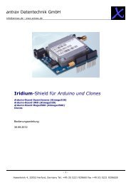
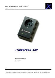
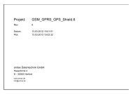
The primary elements of the end-to-end SBD architecture are shown in Figure 2-1. Specifically, the<br />
elements consist of the Field Application (FA), the <strong>Iridium</strong> Subscriber Unit (ISU), the <strong>Iridium</strong> satellite<br />
constellation, the Gateway SBD Subsystem (GSS) located at the <strong>Iridium</strong> gateway, the Internet, and the<br />
Vendor Application (VA.) More details on the system architecture are shown in Figure 2-2.<br />
The Field Application represents the hardware and software that is configured by the VAR for specific<br />
applications such as collecting and transmitting GPS location information. The ISU is an <strong>Iridium</strong> L-Band<br />
Transceiver (LBT) with the SBD feature available in firmware and the service activated on the <strong>Iridium</strong><br />
network. The GSS is responsible for storing and forwarding messages from the ISU to the Vendor<br />
Application and storing messages from the Vendor Application to forward to the ISU. The ISU<br />
communicates with the GSS via the <strong>Iridium</strong> satellite constellation.<br />
Field<br />
Application<br />
[FA]<br />
<strong>Iridium</strong><br />
Subscriber<br />
Unit<br />
[ISU]<br />
<strong>Iridium</strong><br />
Satellite<br />
Constellation<br />
9<br />
<strong>Iridium</strong><br />
Gateway<br />
SBD<br />
Subsystem<br />
[GSS]<br />
Figure 2-1: <strong>Short</strong> <strong>Burst</strong> <strong>Data</strong> Architecture.<br />
<strong>Iridium</strong> Satellite LLC Proprietary & Confidential<br />
IP Socket<br />
or Email<br />
Vendor<br />
Application<br />
[FA]<br />
The interface between the Vendor Application and the GSS uses either standard Internet mail protocols or<br />
an IP Socket type interface to send and receive messages. Mobile terminated messages are sent to the<br />
GSS using a common email or IP address, identifying the specific ISU by encoding the unique ISU IMEI in<br />
the subject line of the email or as part of the IP Socket payload. For email the data message itself is<br />
transported as a binary attachment to the email. For IP Socket the data message is part of the payload.<br />
Messages sent to the Vendor Application are delivered to a specific email or IP address that is configured<br />
when the IMEI is provisioned. The delivery address for each IMEI can be changed on-line by the VAR using<br />
the <strong>Iridium</strong> SPNet provisioning tool.<br />
It is also possible for one ISU to send a message direct to another ISU(s) without the message passing to<br />
the Vendor Application. The second ISU destination IMEI must be programmed on-line by the VAR using<br />
the <strong>Iridium</strong> SPNet provisioning tool. However, only one delivery type (email or ISU-ISU) is permitted. Up to<br />
five email addresses or five ISU IMEIs or one IP Socket address can be provisioned as destinations for MO-<br />
SBD messages.
<strong>Iridium</strong> Satellite LLC<br />
<strong>Short</strong> <strong>Burst</strong> <strong>Data</strong> <strong>Developers</strong> Guide V2.01<br />
The interface between the FA and the ISU is a serial connection with extended proprietary AT commands.<br />
This interface is used to load and retrieve messages between the ISU and the Field Application.<br />
For a Mobile Originated SBD Message (MO-SBD) the message is loaded into the MO buffer in the ISU<br />
using the +SBDWB or +SBDWT AT Commands, a message transfer session between the ISU and the GSS<br />
is initiated using the AT Command +SBDI[X]. For a Mobile Terminated SBD Message (MT-SBD) the ISU<br />
can either initiate a Mailbox Check using the AT Command +SBDI to check whether a MT message is<br />
qu<strong>eu</strong>ed at the GSS; or the ISU can use the (suitably configured) “SBD Ring Alert” capability to be told when<br />
a MT message is qu<strong>eu</strong>ed at the GSS. The ISU must then retrieve the MT-SBD message from the GSS by<br />
issuing the +SBDIXA command. When the message is received from the GSS it can be retrieved from the<br />
MT buffer in the ISU by the Field Application using the +SBDRB or +SBDRT AT Commands. Additionally a<br />
MT-SBD message can also be retrieved in the same network transaction by the ISU when a MO-SBD<br />
message is sent from the ISU.<br />
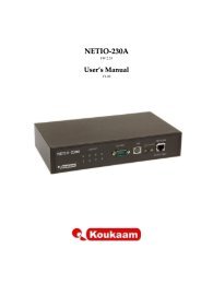
ISU #1<br />
<strong>Iridium</strong> Gateway<br />
10<br />
ETC Subsystem<br />
ETS SEP ECS<br />
SPP<br />
SBD<br />
Subsystem<br />
Figure 2-2: SBD System Architecture<br />
<strong>Iridium</strong> Satellite LLC Proprietary & Confidential<br />
ISU #2<br />
Telephony<br />
Switch<br />
PSTN<br />
IP Socket<br />
or Email<br />
Messages are transferred between the ISU and the GSS using a reliable transport mechanism that ensures<br />
the message is delivered error free. If the ISU was not able to send or receive messages, an indication is<br />
passed to the FA via the serial interface.<br />
The MO and MT message buffers in the ISU will maintain messages as long as the ISU is powered on.<br />
Once a message is transferred from the FA to the MO buffer in the ISU, it will remain there even after it is<br />
successfully sent to the GSS. If a MT message is received at the ISU from the GSS, it will remain in the MT<br />
buffer even after the FA reads it. The buffers in the ISU will be cleared only when either given an explicit<br />
command (+SBDD) or when the ISU is power cycled or is overwritten with new data. The MT buffer will be<br />
cleared when a SBD session is initiated with the +SBDI command.
<strong>Iridium</strong> Satellite LLC<br />
<strong>Short</strong> <strong>Burst</strong> <strong>Data</strong> <strong>Developers</strong> Guide V2.01<br />
All MO and MT messages between the VA and the GSS are routed to the Internet by default. <strong>Iridium</strong> offers<br />
additional cost options for Virtual Private Network (VPN) and leased line routing of email or IP Socket<br />
messages to provide additional security, capacity and/or redundancy if required for the application. ISU-ISU<br />
SBD messages remain entirely within the <strong>Iridium</strong> network infrastructure, however it should be noted that<br />
they pass through the <strong>Iridium</strong> gateway and do not transfer directly from one ISU to another.<br />
2.2 Transceiver Overview<br />
The following <strong>Iridium</strong> transceivers are capable of <strong>Short</strong> <strong>Burst</strong> <strong>Data</strong> <strong>Service</strong>.<br />
The 9522A L-Band Transceiver The 9601 SBD Transceiver<br />
<strong>Developers</strong> should consult the appropriate developers guide document for the transceiver hardware.<br />
11<br />
<strong>Iridium</strong> Satellite LLC Proprietary & Confidential
<strong>Iridium</strong> Satellite LLC<br />
<strong>Short</strong> <strong>Burst</strong> <strong>Data</strong> <strong>Developers</strong> Guide V2.01<br />
3.0 Vendor Application to GSS Email Interface Description<br />
Applications that utilize SBD will communicate to the <strong>Iridium</strong> network via the GSS interface. This interface<br />
utilizes email or IP Socket interfaces for the transfer of data messages to and from the Vendor Application.<br />
This section describes how to utilize the GSS interface in both Mobile Originated and Mobile Terminated<br />
cases. Mobile Terminated messages are messages originated by the Vendor Application (or another ISU),<br />
that are sent to the Field Application. Mobile Originated messages are messages originated by the Field<br />
Application that are sent to either the Vendor Application or to another ISU.<br />
In the case of ISU-ISU SBD messages, the originating message from the first IMEI is a Mobile Originated<br />
Message. Once received and processed in the GSS the message then becomes a Mobile Terminated<br />
Message with respect to the second ISU.<br />
For ISU’s provisioned to use email, each MO or MT message the VA will receive an email for each session<br />
that reaches the GSS regardless of any message transfer, unless one or both of the ISUs are provisioned to<br />
send to another ISU, in which case only the ISU provisioned to send to an email address will receive email<br />
notifications.<br />
This section describes in more detail the operation of Mobile Terminated, Mobile Originated in email mode.<br />
‘ISU to ISU’mode, which is independent of email or IP Socket, is described separately in Section 4.2.<br />
12<br />
<strong>Iridium</strong> Satellite LLC Proprietary & Confidential
<strong>Iridium</strong> Satellite LLC<br />
<strong>Short</strong> <strong>Burst</strong> <strong>Data</strong> <strong>Developers</strong> Guide V2.01<br />
3.1Mobile Terminated Messages<br />
In order to send a MT message from the Vendor Application to the Field Application, the Vendor Application<br />
must send the message to the GSS where it will be qu<strong>eu</strong>ed for delivery awaiting contact from the ISU to<br />
retrieve it. The message will remain in the qu<strong>eu</strong>e for up to five (5) days awaiting contact from the ISU to<br />
retrieve it. After five days all the messages are removed from the qu<strong>eu</strong>e automatically by the GSS. There<br />
are two methods for the ISU to retrieve a qu<strong>eu</strong>ed MT messages from the GSS. The methods are hardware<br />
and firmware dependant. For specific capabilities consult the firmware release notes for the particular ISU<br />
type. <strong>Iridium</strong> recommends using the latest release of firmware available in order to provide the best<br />
performance and compatibility to the functionality described herein.<br />
The first method, caled “Poling,” is universal to all ISUs that are capable of SBD. In this method the mailbox<br />
check command (AT+SBDI with an empty Send Buffer) is sent from the Field Application to the ISU. The<br />
ISU contacts the GSS and transfers the MT message if one is qu<strong>eu</strong>ed.<br />
The second method is called “SBD Ring Alert.” In this method the GSS automatically notifies the ISU that a<br />
message is qu<strong>eu</strong>ed at the GSS. Note that the MT message is not automatically delivered to the ISU. The<br />
application designer has to program the Field Application to respond in an appropriate manner to the SBD<br />
Ring Alert. Figure 3-1 provides an example MT email message. MT messages must follow the formatting<br />
rules are outlined below:<br />
� The ISU must be provisioned in SPNet to send SBD Ring Alerts. If this is not done the GSS will not send<br />
any SBD Ring Alerts even if new MT messages are qu<strong>eu</strong>ed by the Vendor Application and/or the ISU is<br />
suitably configured.<br />
� Messages sent to an ISU from the VA are sent to the email address: data@sbd.iridium.com<br />
� Placing at least one, and up to a total of four, IMEI(s) into the subject line of the email identifies the<br />
destination ISU(s).<br />
o If there is more than one destination IMEIs then list the additional IMEIs on the subject line<br />
separated with a single space between each IMEI.<br />
� The message must contain a properly formated sender (“From:” address),otherwise the message will<br />
be dropped by the GSS.<br />
� The data message to the ISU must be carried as an attachment to the email:<br />
o The attachment name must have a ‘.sbd’file name extension: E.g. ‘importantdata.sbd’<br />
o File names can be up to 80 characters. (Including the .sbd extension.)<br />
o File names are not case sensitive.<br />
� The maximum size of the binary message (not the Base64 version) is ISU specific<br />
and is between one byte and the maximum MT message size stated in Section 1.6<br />
� The GSS will reject message sizes that are too large for a particular ISU type.<br />
o The attachment must use standard Multipurpose Internet Mail Extensions (MIME) Base64<br />
encoding as defined in RFC 2045.<br />
� Multiple messages may be qu<strong>eu</strong>ed by a single email by including the additional separate attachments in<br />
the email message, subject to the maximum number of messages permitted in the qu<strong>eu</strong>e.<br />
o Note that if one of the attachments has an incorrect extension (.sbd), while others are correct<br />
then no error indication email will be sent.<br />
o A single email with multiple attachments creates a MT-SBD message for each attachment. In<br />
other words –one email with ten attachments creates ten MT-SBD messages for the destination<br />
ISU.<br />
� A maximum of 50 messages may be in any ISU’s qu<strong>eu</strong>e at any one timeregardless of whether they<br />
where sent as an individual message with attachment or a single message with multiple attachments.<br />
The GSS will reject any message over this limit.<br />
� The message body plays no role in the message transfer process; any information contained in the body<br />
will be discarded by the GSS.<br />
13<br />
<strong>Iridium</strong> Satellite LLC Proprietary & Confidential
<strong>Iridium</strong> Satellite LLC<br />
<strong>Short</strong> <strong>Burst</strong> <strong>Data</strong> <strong>Developers</strong> Guide V2.01<br />
To: data@sbd.iridium.com<br />
From: VA@VendorDomain.com<br />
Subject: 304050607080903<br />
Figure 3-1: Mobile Terminated Email Message<br />
The GSS validates each MT message upon receipt and returns a disposition notification email to the MT<br />
message originator. The format of this email is shown in Figure 3-2 and the definition of the email header<br />
and body descriptors is shown in Table 3-1. A sample success notification is shown in Figure 3-3. If there is<br />
more than one destination ISU a disposition notification email will be sent for each destination ISU. If the<br />
Vendor Application attempts to qu<strong>eu</strong>e more than 50 messages for delivery at the GSS, a rejection notice<br />
email similar to Figure 3-4 will be sent to the message originator (From address).<br />
To: VA@VendorDomain.com<br />
From: techops@iridium.com<br />
Subject: : <br />
<br />
IMEI: <br />
Time: <br />
Figure 3-2: MT-SBD Email disposition notification message field layout.<br />
14<br />
<strong>Iridium</strong> Satellite LLC Proprietary & Confidential
<strong>Iridium</strong> Satellite LLC<br />
<strong>Short</strong> <strong>Burst</strong> <strong>Data</strong> <strong>Developers</strong> Guide V2.01<br />
Table 3-1 SBD-MT disposition notification email header and message body field descriptors<br />
Field Name Description<br />
This field will have one of the following values:<br />
<br />
<br />
<br />
SBD Mobile Terminated Message Qu<strong>eu</strong>ed for Unit: <br />
Error: SBD Mobile-Terminated Message Not Qu<strong>eu</strong>ed for Unit: <br />
Field Value Description<br />
No IMEI provided in the subject line of the email sent to the<br />
(No IMEI specified)<br />
GSS.<br />
The IMEI in the subject line of the email sent to the GSS was<br />
(Invalid IMEI specified) not in the proper format. Additional information can be found in<br />
the reason code in the body of the message<br />
The actual 15 digit IMEI of the destination ISU is returned if it<br />
Actual IMEI<br />
was validated.<br />
Additional text expanding on the qu<strong>eu</strong>ing disposition in the subject line. It will have one<br />
of the following values:<br />
The following mobile-terminated message was qu<strong>eu</strong>ed for delivery:<br />
The following mobile-terminated message was not qu<strong>eu</strong>ed for delivery:<br />
The hardware identification number of the unit to which the message was to be qu<strong>eu</strong>ed.<br />
Field Value Description<br />
IMEI (none specified) No IMEI provided in the subject line of the email sent to the GSS.<br />
The IMEI was received by the GSS. In the case of Success, this is<br />
Received IMEI the 15 numeric-digit IMEI of the ISU. In the case of Error, this is the<br />
invalid Alpha-numeric string received by the GSS.<br />
Time The timestamp, in UTC, when the acknowledgement was sent from the GSS.<br />
Attachment Filename The filename of the attachment received by the GSS.<br />
Attachment Size The size of the attachment received by the GSS.<br />
<br />
One of the following values will be displayed:<br />
The MTMSN is XX, and the message is number N in the qu<strong>eu</strong>e<br />
Reason: IMEI length (M) is invalid –must be 15 characters.<br />
Reason: The IMEI is not provisioned on the SBD system.<br />
Reason: No atachment with a ‘.sbd’ file extension was found<br />
Reason: Payload size is too large (max size allowed is XXXX bytes).<br />
Reason: Mobile-termination message qu<strong>eu</strong>e for the IMEI is full (max of 50<br />
allowed).<br />
15<br />
<strong>Iridium</strong> Satellite LLC Proprietary & Confidential
<strong>Iridium</strong> Satellite LLC<br />
<strong>Short</strong> <strong>Burst</strong> <strong>Data</strong> <strong>Developers</strong> Guide V2.01<br />
To: VA@VendorDomain.com<br />
From: sbdservice@sbd.iridium.com<br />
Subject: Success: SBD Mobile-Terminated Message Qu<strong>eu</strong>ed for Unit<br />
300001001247240<br />
The following mobile-terminated message was qu<strong>eu</strong>ed for delivery:<br />
IMEI: 300001001247240<br />
Time: Mon Oct 27 17:24:29 2003<br />
Attachment Filename: TestFile518chars.sbd<br />
Attachment Size: 518 bytes<br />
The MTMSN is 6870, and the message is number 12 in the qu<strong>eu</strong>e<br />
Figure 3-3: Mobile Terminated Email Message –Successful Qu<strong>eu</strong>ing Notice<br />
To: VA@Vendordomain.com<br />
From: sbdservice@sbd.iridium.com<br />
Subject: Error: SBD Mobile-Terminated Message Not Qu<strong>eu</strong>ed for Unit:<br />
300001001247240<br />
The following mobile-terminated message was not qu<strong>eu</strong>ed for delivery:<br />
IMEI: 300001001247240<br />
Time: Mon Oct 27 17:23:30 2003<br />
Attachment Filename: TestFile518chars.sbd<br />
Attachment Size: 518 bytes<br />
Reason: Mobile-termination message qu<strong>eu</strong>e for the IMEI is full (max of 50<br />
allowed).<br />
Figure 3-4: Mobile Terminated Email Message - Rejection Notice<br />
16<br />
<strong>Iridium</strong> Satellite LLC Proprietary & Confidential
<strong>Iridium</strong> Satellite LLC<br />
<strong>Short</strong> <strong>Burst</strong> <strong>Data</strong> <strong>Developers</strong> Guide V2.01<br />
3.2Mobile Originated Messages Sent Via Email<br />
Messages sent from the ISU to the GSS are processed at the GSS where they are immediately formatted<br />
and sent to the destination email address that was provisioned when the ISU IMEI was provisioned. The<br />
message sent to the Vendor Application from the ISU will be carried as a binary attachment to an email from<br />
the GSS to the Vendor Application. The binary attachment is encoded using standard MIME Base64<br />
encoding as defined in RFC 2045. Unlike Mobile Terminated messages sent to the GSS, Mobile Originated<br />
messages sent to the Vendor Application carry additional information in the email message body. This<br />
information includes the Mobile Originated Message Sequence Number (MOMSN), the time of the session,<br />
the session status, the message size, and ISU specific geo-location information. The format of such an<br />
email message is provided in Figure 3-5, details of the email message fields are provided in Table 3-2. Note<br />
that it is possible to tell the GSS not to send the geographic location fields on a device by device basis. This<br />
is achieved by using SPNet and un-checking the “Include Geo-<strong>Data</strong>” box for the specific ISU IMEI. An<br />
example of an email message with no geo-location information is shown in Figure 3-6.<br />
A MO-SBD message may be sent to up to five email destinations. The five destinations are programmed<br />
into the GSS by using the SPNet provisioning tool available to Value Added Resellers. Note that only one<br />
delivery method is permitted: Either email or ISU-ISU, it is not possible to mix delivery types. [See also<br />
Section 4.2 “ISU to ISU Messages.”]<br />
From: sbdservice@sbd.iridium.com<br />
Sent: Tuesday, August 13, 2002 16:51 PM<br />
Subject: SBD Msg From Unit: 304050607080903<br />
MOMSN: 2<br />
MTMSN: 239<br />
Time of Session (UTC): Tue Aug 13 16:51:04 2002<br />
Session Status: 00 - Transfer OK<br />
Message Size (bytes): 1230<br />
Figure 3-5: Mobile Originated Email Message Showing Geo-location information<br />
From: sbdservice@sbd.iridium.com<br />
Sent: Friday, July 8, 2005 00:12 AM<br />
Subject: SBD Msg From Unit: 300003000210150<br />
MOMSN: 652<br />
MTMSN: 644<br />
Time of Session (UTC): Fri Jul 8 00:12:55 2005<br />
Figure 3-6: Mobile Originated Email Message without Geo-location information<br />
17<br />
<strong>Iridium</strong> Satellite LLC Proprietary & Confidential
<strong>Iridium</strong> Satellite LLC<br />
<strong>Short</strong> <strong>Burst</strong> <strong>Data</strong> <strong>Developers</strong> Guide V2.01<br />
Table 3-2: Mobile Originated Message Email Message Field Description<br />
Field Name Description<br />
From<br />
This field identifies the sender of the email message as the SBD <strong>Service</strong>. This field normally<br />
contains “sbdservice@sbd.iridium.com”<br />
Sent<br />
This field provides the time at which the message was emailed from the GSS to the Vendor<br />
Application. The timestamp is in UTC.<br />
Subject This field provides the ISU IMEI of the unit that sent the MO message.<br />
This is the Message Sequence Number set by the ISU when the message was sent from the ISU<br />
MOMSN<br />
to the GSS. The value is an integer in the range 0 to 65,535 and is incremented each time an SBD<br />
session is successfully completed between the ISU to the GSS. It is a wrap around counter which<br />
will increment to 0 after reaching 65535.<br />
This is the Message Sequence Number used by the GSS when the message was sent from the<br />
GSS to the ISU. The value is an integer in the range 0 to 65,535 and is incremented each time the<br />
MTMSN GSS forwards a message to a particular ISU. It is a wrap around counter which will increment to 1<br />
after reaching 65535. It will have a value of zero (0) if no MT message transfer attempt occurred to<br />
the specific ISU.<br />
This field provides the UTC timestamp of the ISU session between the ISU and the GSS. A text<br />
string is sent with the folowing format: “DDD MMM dd HH:MM:SS yyyy”.<br />
Value Description<br />
Time of DDD Day of the week (Sun, Mon, Tue, Wed, Thu, Fri, Sat)<br />
Session MMM Month of the year (Jan, Feb, Mar, Apr, May, Jun, Jul, Aug, Sep, Oct, Nov, Dec)<br />
dd Day of the month (01 to 31)<br />
hh Hour (00 to 23) mm Minute (00 to 59) ss Second (00 to 59)<br />
yyyy Year<br />
There are seven possible results of the SBD session which are described below:<br />
Session<br />
Status<br />
Message Size<br />
Unit Location<br />
Session Status Description<br />
00 - Transfer OK<br />
The SBD session between the ISU and the GSS completed<br />
successfully.<br />
01 - MT Message Too Large<br />
The MT message qu<strong>eu</strong>ed at the GSS is too large to be transferred<br />
within a single SBD session<br />
10 - SBD Timeout The SBD Session timed out before session completion<br />
12 - MO Message Too Large<br />
The MO message being transferred by the ISU is too large to be<br />
transferred within a single SBD session<br />
13 - Incomplete Transfer A RF link loss occurred during the SBD session<br />
14 - SBD Protocol Error An ISU protocol anomaly occurred during the SBD session<br />
15 - SBD Denial The ISU is not allowed to access the system<br />
This field provides an indication of the size, in bytes, of the attached message in decoded form.<br />
This is not the length of the MIME encoded data.<br />
These fields are optional at the time that the ISU is provisioned. These fields provide the<br />
geographic location of the ISU. The latitude and longitude provide a center point and the CEP<br />
Radius provides the radius (measured in Kilometers) around the center point within which the unit<br />
is located. This reported position is accurate (within the reported circle) 80% of the time. Note that<br />
activating or deactivating the inclusion of the ISU location can only be accomplished via SPNet. It<br />
cannot be controlled by or from the ISU and is enabled by default.<br />
This field provides the geographic latitude of the ISU measured in degrees.<br />
Unit Latitude Positive represents north, negative represents south. When GEO location<br />
data is provisioned to “of” the latitude the field is not included in the email.<br />
This field provides the geographic longitude of the ISU measured in degrees.<br />
Unit Longitude Positive represents east, negative represents west. When GEO location data<br />
is provisioned to “of” the longitude the field is not included in the email.<br />
This field provides an estimate of the accuracy of the ISU’s location. This<br />
CEPRadius position is reported in Kilometers. When GEO location data is provisioned to<br />
“of” the CEPRadius the field is not included in the email.<br />
18<br />
<strong>Iridium</strong> Satellite LLC Proprietary & Confidential
<strong>Iridium</strong> Satellite LLC<br />
<strong>Short</strong> <strong>Burst</strong> <strong>Data</strong> <strong>Developers</strong> Guide V2.01<br />
3.3Examples of SBD Usage<br />
This section outlines some generic examples of SBD usage scenarios. The scenarios are merely examples<br />
and developers may use the SBD AT Commands in other permutations and combinations.<br />
3.3.1 Mobile Originated (MO) Message<br />
The FA will load a Mobile Originated message into the ISU, initiate a SBD session, evaluate and act on the<br />
results of the SBD session (Table 3-3). Finally, the GSS will forward the MO message to the Vendor<br />
Application. (Figure 3-7.)<br />
Table 3-3 FA to ISU Interface, MO Message<br />
To ISU (from DTE) To DTE (from ISU) Description<br />
AT+SBDWB=351�<br />
The FA instructs the ISU that it will write a 351 byte<br />
message into the ISU.<br />
READY�<br />
The ISU informs the FA that it is ready to receive the<br />
message<br />
The FA sends the 351 byte message followed by the<br />
Binary transfer<br />
two byte checksum to the ISU.<br />
echoed.<br />
This transfer is not<br />
0�<br />
The ISU will send a zero result code to the FA<br />
indicating that the message was loaded without error.<br />
AT+SBDI� The FA instructs the ISU to initiate an SBD transfer.<br />
The ISU informs the FA that the message was sent<br />
+SBDI: 1, 23, 0, -1, 0, 0� successfully using MOMSN 23. No MT message<br />
AT+SBDD0�<br />
was received and no MT messages are qu<strong>eu</strong>ed.<br />
The FA instructs the ISU to clear the message from<br />
the Mobile Originated buffer.<br />
0�<br />
The ISU informs the FA that the message buffer was<br />
cleared successfully.<br />
From: sbdservice@sbd.iridium.com<br />
Sent: Tuesday, August 13, 2002 12:49 PM<br />
Subject: SBD Msg From Unit: 304050607080903<br />
MOMSN: 23<br />
MTMSN: 0<br />
Time of Session (UTC): Tue Aug 13 16:51:04 2002<br />
Session Status: 00 - TRANSFER OK<br />
Message Size (bytes): 351<br />
Unit Location: Lat = 59.372463 Long = 75.309806<br />
CEPradius = 3<br />
Message is Attached.<br />
Figure 3-7 VA to GSS Interface, MO Message<br />
19<br />
<strong>Iridium</strong> Satellite LLC Proprietary & Confidential
<strong>Iridium</strong> Satellite LLC<br />
<strong>Short</strong> <strong>Burst</strong> <strong>Data</strong> <strong>Developers</strong> Guide V2.01<br />
3.3.2 Mailbox Check / Mobile Terminated (MT) Message<br />
The GSS does not have the ability to automatically notify the ISU that a Mobile Terminated message is<br />
waiting for it at the GSS. The FA is required to perform a Mailbox Check by initiating an SBD session with an<br />
empty MO buffer. If a MT message is waiting for the ISU at the GSS, the MT message is transmitted to the<br />
ISU.<br />
In this scenario, a MT message is sent from the Vendor Application to the GSS (Figure 3-8.) The FA will<br />
initiate an SBD session, evaluate the results of the SBD session, and read the MT message from the ISU<br />
(Table 3-4). After the SBD session completes, the GSS sends an email message to the Vendor Application<br />
indicating the disposition of the SBD session (Figure 3-9).<br />
To: <strong>Data</strong>@SBD.<strong>Iridium</strong>.com<br />
From: VA@VendorDomain.com<br />
Subject: 304050607080903<br />
Figure 3-8 VA to GSS Interface, Mailbox Check / MT Message<br />
From: <br />
Sent: Tuesday, August 13, 2002 12:49 PM<br />
Subject: SBD Msg From Unit: 304050607080903<br />
MOMSN: 498<br />
MTMSN: 237<br />
Time of Session (UTC): Tue Aug 13 16:51:04 2002<br />
Session Status: 00 - TRANSFER OK<br />
Message Size (bytes): 0<br />
Figure 3-9 GSS to VA Interface, Status Message.<br />
Table 3-4 FA to ISU Interface, Mailbox Check / MT Message<br />
To ISU<br />
(from DTE)<br />
To DTE (from ISU) Description<br />
AT+SBDD0 The FA instructs the ISU to clear the send buffer.<br />
AT+SBDI� The FA instructs the ISU to initiate an SBD transfer.<br />
The ISU informs the FA that no MO message was<br />
+SBDI: 0, 498, 1, 237, 561, 2�<br />
sent and a 561 byte MT message was successfully<br />
received with MTMSN 237. Two additional MT<br />
messages are qu<strong>eu</strong>ed.<br />
AT+SBDRB� The FA instructs the ISU to transfer the MT message.<br />
The ISU sends a two-byte length indicator followed<br />
Binary transfer<br />
by the 561 byte message followed by the two byte<br />
checksum to the FA.<br />
20<br />
<strong>Iridium</strong> Satellite LLC Proprietary & Confidential
<strong>Iridium</strong> Satellite LLC<br />
<strong>Short</strong> <strong>Burst</strong> <strong>Data</strong> <strong>Developers</strong> Guide V2.01<br />
3.3.3 Mobile Originated and Mobile Terminated Message<br />
When the Field Application needs to send a Mobile Originated data message and the Vendor Application<br />
needs to send a Mobile Terminated Message, the following scenario assumes that the MT Message is<br />
waiting at the GSS before the MO message is sent.<br />
In this scenario, the Vendor Application will send the MT message to the GSS (Figure 3-10); the FA will load<br />
the MO message into the ISU, initiate an SBD session, evaluate the results of the SBD session, and read<br />
the Mobile Terminated message from the ISU (Table 3-5). Finally the Vendor Application will receive the MO<br />
message (Figure 3-11).<br />
To: <strong>Data</strong>@SBD.<strong>Iridium</strong>.com<br />
From: VA@VendorDomain.com<br />
Subject: 304050607080903<br />
Figure 3-10 Vendor Application to GSS Interface, MT Message<br />
Table 3-5 FA to ISU Interface, Mobile Originated and Mobile Terminated<br />
To ISU (from DTE) To DTE (from ISU) Description<br />
AT+SBDWB=351� The FA instructs the ISU that it will write a<br />
351 byte message into the ISU.<br />
READY� The ISU informs the FA that it is ready to<br />
receive the message<br />
Binary transfer The FA sends the 351-byte message<br />
followed by the two byte checksum to the<br />
ISU. This transfer is not echoed.<br />
0� The ISU will send a zero result code to the<br />
FA indicating that the message was loaded<br />
without error.<br />
AT+SBDI� The FA instructs the ISU to initiate an SBD<br />
transfer.<br />
+SBDI: 1, 2173, 1, 87, 429, 0� The ISU informs the FA that the message<br />
was sent successfully using MOMSN 2173.<br />
A 429-byte message was received using<br />
MTMSN 87. No additional messages are<br />
qu<strong>eu</strong>ed.<br />
AT+SBDD0� The FA instructs the ISU to clear the<br />
message from the send buffer.<br />
0� The ISU informs the FA that the message<br />
buffer was cleared successfully.<br />
AT+SBDRB� The FA instructs the ISU to transfer the<br />
received message.<br />
Binary transfer The ISU sends a two-byte length indicator<br />
followed by the 429byte message followed by<br />
the two byte checksum to the FA.<br />
21<br />
<strong>Iridium</strong> Satellite LLC Proprietary & Confidential
<strong>Iridium</strong> Satellite LLC<br />
<strong>Short</strong> <strong>Burst</strong> <strong>Data</strong> <strong>Developers</strong> Guide V2.01<br />
From: <br />
Sent: Tuesday, August 13, 2002 12:49 PM<br />
Subject: SBD Msg From Unit: 304050607080903<br />
MOMSN: 2173<br />
MTMSN: 87<br />
Time of Session (UTC): Tue Aug 13 16:51:04 2002<br />
Session Status: 00 - TRANSFER OK<br />
Message Size (bytes): 351<br />
Figure 3-11 VA to GSS Interface, MO Message<br />
3.4 Permitted Email Address Formats<br />
The following formats of email address are permitted for Mobile Originated messages:<br />
� Name@domain.com<br />
o E.g. <strong>Iridium</strong>SBDProcessor@Iridum.varname.com<br />
� Name@IP_address<br />
o E.g. <strong>Iridium</strong>SBDProcessor@172.16.254.1<br />
Note that <strong>Iridium</strong> encourages the use of Name@domain.com. Use of Name@IP_address is discouraged as<br />
per the relevant RFC2821.<br />
3.5 Bit Bucket for MO-SBD Messages<br />
In certain circumstances a VAR may want to cause all MO-SBD messages to be discarded and not sent to<br />
the Vendor Application. If a SBD IMEI is provisioned in SPNet to "devnull@devnull.iridium.com", then all<br />
mobile originated messages will be immediately discarded after leaving the SPP. The emails are not stored<br />
or sent anywhere, but literally sent to the /dev/null device of the mail servers. Additionally all mailbox check<br />
email notifications are also immediately discarded. To summarize, if devnull@devnull.iridium.com is<br />
provisioned for an IMEI then *all* email messages and notifications that result from a MO-SBD<br />
transaction are discarded and it is *not* possible to recover such messages.<br />
This email address is not accessible outside of <strong>Iridium</strong> and is only available for emails generated within the<br />
GSS. An email sent to this address from outside of <strong>Iridium</strong> will be rejected.<br />
Even if a message is delivered to devnull@devnull.iridium.com, the message will still be charged for.<br />
Messages sent to devnull cannot be retrieved.<br />
22<br />
<strong>Iridium</strong> Satellite LLC Proprietary & Confidential
<strong>Iridium</strong> Satellite LLC<br />
<strong>Short</strong> <strong>Burst</strong> <strong>Data</strong> <strong>Developers</strong> Guide V2.01<br />
4.0 SBD Automatic Notification for Mobile Terminated<br />
Messages and ISU-ISU Messages<br />
The <strong>Iridium</strong> <strong>Short</strong> <strong>Burst</strong> <strong>Data</strong> service is a fully acknowledged protocol that confirms the delivery of the<br />
messages between the ISU and the GSS. By design, Mobile Originated messages are fully acknowledged<br />
as the ISU is in full control of the transmission. For Mobile Terminated messages the protocol does not<br />
permit the GSS to send an unsolicited MT-SBD message to an ISU as the ISU may not be ready or<br />
available to receive such a message and acknowledge it. Each time the GSS receives a MT-SBD message<br />
for an ISU, it is qu<strong>eu</strong>ed at the GSS until the ISU requests delivery. A capability of notifying the ISU that it has<br />
a qu<strong>eu</strong>ed MT-SBD message waiting for it has been implemented and that capability is called SBD Automatic<br />
Notification.<br />
Prior to the release of SBD GSS Version 4.1, the ISU did not receive a notification that a MT-SBD message<br />
had been qu<strong>eu</strong>ed at the GSS. In order to determine if a message was qu<strong>eu</strong>ed for delivery, the ISU sent<br />
either a MO-SBD message or a ‘mailbox check’ and then the application checked the status codes returned<br />
from the GSS to determine if a MT-SBD message was received by the ISU and whether additional<br />
messages were still qu<strong>eu</strong>ed at the GSS. For applications that required timely notification of qu<strong>eu</strong>ed MT-SBD<br />
messages this process was less than optimal.<br />
To provide a more optimal solution <strong>Iridium</strong> implemented the SBD Automatic Notification feature in SBD GSS<br />
Version 4.1. This feature notifies the ISU that a MT-SBD message has been qu<strong>eu</strong>ed for it at the GSS. It<br />
does not automatically deliver the MT-SBD message. The actual notification is called a SBD Ring Alert. The<br />
application developer will need to implement an appropriate algorithm in the Field Application to process the<br />
SBD Ring Alert and then initiate a SBD session to receive the qu<strong>eu</strong>ed message.<br />
4.1SBD Automatic Notification for Mobile Terminated Messages<br />
This section provides basic examples of how to configure the ISU. Please also consult the relevant AT<br />
Command set documentation for more detailed information. SBD Automatic Notification requires both<br />
the correct configuration of the ISU through use of AT Commands and the activation of this feature<br />
at the time of provisioning through the use of SPNet.<br />
4.1.1 Automatic Notification Registration<br />
To implement the SBD Ring Alert feature there are a number of implementation steps required:<br />
1. The ISU must have the firmware revision that supports this feature. See Section 1.6. These<br />
versions can be downloaded from the extranet site if required.<br />
2. In the SPNet provisioning database, the SBD Ring Alert option needs to be selected in the<br />
provisioning screen for the ISU. This option indicates to the GSS that SBD Ring Alerts are<br />
intended to be used with this ISU. NOTE: In the majority of the instances where it is reported<br />
that “ring alerts are not working,” it is due to not selecting the Ring Alert option in SPNet for the<br />
ISU.<br />
3. The Field Application is required to execute AT commands to configure the ISU to listen for SBD<br />
Ring Alerts and then the ISU has to complete SBD Network Registration which notifies the GSS<br />
23<br />
<strong>Iridium</strong> Satellite LLC Proprietary & Confidential
<strong>Iridium</strong> Satellite LLC<br />
<strong>Short</strong> <strong>Burst</strong> <strong>Data</strong> <strong>Developers</strong> Guide V2.01<br />
that the ISU is ready to receive SBD Ring Alerts.<br />
a. The Field Application executes +SBDMTA command to configure the ISU to listen for SBD<br />
Ring Alerts sent from the GSS. Failure to complete this step will result in the ISU not<br />
listening for SBD Ring Alerts as this is the default setting. To configure the ISU to receive<br />
the SBD Ring Alert the command is: AT+SBDMTA=1.<br />
b. The Field Application next executes the +SBDREG command which will attempt to<br />
complete the SBD Network Registration. SBD Network Registration performs two functions.<br />
First it notifies the GSS that the ISU is configured and ready to receive SBD Ring Alerts and<br />
second it provides the required geo-location coordinates so that the GSS knows where to<br />
route the SBD Ring Alert(s) to. To complete the SBD Network Registration the command is:<br />
AT+SBDREG.<br />
The table below describes the following: The FA verifies its registration state, performs a registration in order<br />
to be able to receive automatic notifications, and enables automatic notification indications.<br />
To ISU (from FA) To FA (from ISU) Description<br />
AT+SBDMTA=1<br />
Tell the ISU to listen for (enable) SBD Ring<br />
OK<br />
Alerts.<br />
AT+SBDREG? Query the ISU SBD Network Registration status<br />
+SBDREG:0 ISU has not completed SBD Network<br />
Registration, ie it is detached.<br />
AT+SBDREG Tell the ISU to register for SBD Ring Alerts<br />
+SBDREG:2,0 ISU is now registered for SBD Ring Alerts<br />
AT+SBDREG? Query the ISU SBD Network Registration status<br />
+SBDREG:2 ISU is registered for SBD Ring Alerts<br />
4.1.2 Retrieval of a MT-SBD Message using SBD Automatic<br />
Notification<br />
The ISU must send a MO-SBD message in order to retrieve the MT-SBD message qu<strong>eu</strong>ed at the GSS. The<br />
MO-SBD may simply be a ‘mailbox check’ which has a zero-byte message payload or a valid MO-SBD<br />
message (i.e. payload size greater than zero bytes.) Either one will cause the next MT-SBD message<br />
qu<strong>eu</strong>ed at the GSS, if there is one, to be delivered to the ISU and retrieve the status information from the<br />
GSS.<br />
If the application is configured to use the SBD Automatic Notification, the +SBDIX and +SBDIXA commands<br />
must be used to initiate the MO-SBD message. To respond to a SBD Ring Alert the Field Application should<br />
use the +SBDIXA command to retrieve the MT-SBD message. If the Field Application is sending an<br />
unsolicited MO-SBD message, the +SBDIX command is used. [Note: The +SBDI command can still be<br />
used, however, it also ‘detaches’ or stops SBD Ring Alerts being sent from GSS.]<br />
24<br />
<strong>Iridium</strong> Satellite LLC Proprietary & Confidential
<strong>Iridium</strong> Satellite LLC<br />
<strong>Short</strong> <strong>Burst</strong> <strong>Data</strong> <strong>Developers</strong> Guide V2.01<br />
In the table below: The FA verifies its registration state. Upon receiving a SBD Ring Alert the FA initiates an SBD<br />
session to receive an MT message.<br />
To ISU (from FA) To FA (from ISU) Description<br />
AT+SBDREG? Query the ISU SBD Network Registration status<br />
+SBDREG:2 ISU is registered for SBD Ring Alerts<br />
…<br />
Vendor Application sends an MT message to the<br />
GSS. GSS sends a SBD Ring Alert to ISU<br />
+SBDRING<br />
ISU indicates an incoming message. The RI line also<br />
toggles.<br />
AT+SBDIXA<br />
FA initiates an SBD session in response to the SBD<br />
AT+SBDRB<br />
+SBDIXA:0,23,1,237,90,2<br />
<br />
Ring Alert<br />
4.1.3 SBD Ring Alert Status Information<br />
ISU informs FA that a 90-byte message was<br />
successfully received with MTMSN 237, and that two<br />
further MT messages are qu<strong>eu</strong>ed at the GSS<br />
FA retrieves the received message from the ISU<br />
During a SBD message transfer, status information is transferred between the GSS and the ISU. This status<br />
information is retrieved from the ISU by using the +SBDSX command which returns six values: MO flag,<br />
MOMSN, MT flag, MTMSN, RA flag and number of messages waiting at the GSS. The parameters MO flag,<br />
MOMSN, MT flag, MTMSN are the same as those returned by the +SBDS command. The new parameters<br />
are the RA flag and the messages waiting. The RA flag indicates whether the ISU received a SBD Ring Alert<br />
from the GSS that has not been answered. The messages waiting value is the number of MT messages<br />
qu<strong>eu</strong>ed at the GSS waiting to be delivered. This information can be used by the Field Application to retrieve<br />
the qu<strong>eu</strong>ed messages.<br />
This status information is updated every time there is a SBD session between the ISU and the GSS. The<br />
commands that initiate an SBD session are: +SBDI, +SBDIX[A], +SBD[A]REG, +SBDDET. The +SBDSX<br />
command can be properly used following any of these commands.<br />
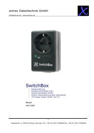
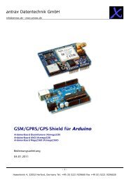
4.1.4 Field Application Implementation<br />
4.1.4.1 Power Up<br />
� On power up, the Field Application configures the ISU to receive the SBD Ring Alert with the<br />
+SBDMTA command.<br />
� This should be followed by the +SBDREG to complete SBD Network Registration of the ISU with the<br />
GSS.<br />
� After the response code for +SBDREG has been received that the ISU has successfully completed<br />
SBD Network Registration, the Field Application can check the current status response with the<br />
+SBDSX command.<br />
o If the GSS received a MT-SBD message for this ISU while it was powered off, it will be<br />
indicated by the RA status flag.<br />
o If there are MT-SBD messages qu<strong>eu</strong>ed for delivery, this is indicated by the ‘message<br />
waiting’ parameter which is a count of the number of messages qu<strong>eu</strong>ed. If there are<br />
messages qu<strong>eu</strong>ed for delivery to this ISU, the application can initiate a SBD session and<br />
retrieve them.<br />
25<br />
<strong>Iridium</strong> Satellite LLC Proprietary & Confidential
<strong>Iridium</strong> Satellite LLC<br />
<strong>Short</strong> <strong>Burst</strong> <strong>Data</strong> <strong>Developers</strong> Guide V2.01<br />
Process<br />
Complete<br />
Wait<br />
Loop<br />
Process<br />
Complete<br />
9601 Power Up Process<br />
NO<br />
NO<br />
9601 Power Up<br />
``<br />
Auto<br />
RA<br />
Notification<br />
AT+SBDMTA=1<br />
AT+CSQ >0<br />
AT+SBDREG<br />
OK?<br />
Message<br />
Waiting?<br />
2<br />
YES<br />
YES<br />
YES<br />
NO<br />
26<br />
Wait Loop<br />
NO<br />
<strong>Iridium</strong> Satellite LLC Proprietary & Confidential<br />
Page 2<br />
AT+CSQ > 0<br />
YES<br />
AT+SBDIX<br />
Status OK<br />
YES<br />
Move MT-SBD<br />
From ISU<br />
To Application<br />
And Process<br />
Another Msg<br />
Waiting<br />
NO<br />
Process<br />
Complete<br />
NO<br />
YES
<strong>Iridium</strong> Satellite LLC<br />
<strong>Short</strong> <strong>Burst</strong> <strong>Data</strong> <strong>Developers</strong> Guide V2.01<br />
4.1.4.2 Automatic SBD Ring Alert Notification& Retry Scheme<br />
When the GSS receives a MT-SBD message and the destination ISU is both configured to listen for SBD<br />
Ring Alerts, and it has successfully completed SBD Network Registration, the GSS sends a SBD Ring Alert<br />
to the ISU. If the ISU does not respond in approximately 13 seconds, a second SBD Ring Alert is sent. If the<br />
ISU does not respond to the second SBD Ring Alert, no further SBD Ring Alerts are sent until another new<br />
MT-SBD is qu<strong>eu</strong>ed for this specific ISU.<br />
If a subsequent MT-SBD message is received at the GSS for this ISU, the SBD Ring Alert process repeats<br />
itself. However, the GSS will not send a SBD Ring Alert if the subsequent MT-SBD is received within 10<br />
seconds of the receipt of the previous MT-SBD.<br />
Note that while the transfer of MO or MT SBD messages is via a reliable (duplex) protocol, SBD Ring Alerts<br />
are sent on a simplex channel. If the ISU is turned off or is blocked from seeing the satellite, then a<br />
SBD Ring Alert will not be received by the ISU and the GSS has no knowledge of whether an ISU<br />
eventually received a specific SBD Ring Alert or not.<br />
If an ISU, configured to receive SBD Ring Alerts, is not powered on and a MT-SBD message is qu<strong>eu</strong>ed at<br />
the GSS then, assuming the ISU is configured in the GSS for SBD Ring Alerts, the SBD Ring Alert will be<br />
sent out. However because the ISU is not powered on, the ISU will not receive the SBD Ring Alert. A<br />
subsequent power-on of the ISU will not cause the SBD Ring Alert to be delivered by the GSS. The GSS<br />
has no direct knowledge of the power on status of ISUs. In order for a Field Application to know whether<br />
there was a qu<strong>eu</strong>ed MT-SBD message at the GSS during the time that the ISU was powered off, the ISU<br />
can use either the +SBDSX command or it could send a MO-SBD message (+SBDI[X]) as specified in [3].<br />
If an ISU is on, and suitably configured, but does not have sufficient line of sight to the satellite due to<br />
terrestrial physical blockage the impact may be similar to the description of the powered off ISU just given.<br />
The behavior will depend on the amount of blockage. Applications designers should not rely on the use of<br />
+CSQ for determining whether an ISU can see a satellite at an instantaneous point in time on the 9601. To<br />
conserve power the +CSQ algorithm uses averaging over time.<br />
4.1.4.3 Retrieving MT-SBD Message from the GSS when notified by the SBD<br />
Ring Alert<br />
The GSS qu<strong>eu</strong>es the MT-SBD message for the ISU and sends SBD Ring Alert. The ISU receives the SBD<br />
Ring Alert and sends an unsolicited response to the Field Application. This response is either SBDRING in<br />
Verbose Mode or “2” in Numeric Mode. The Field Application interprets the response and initiates a SBD<br />
session with the +SBDIXA command. The “A” sufix indicates this is a response to the SBD Ring Alert.<br />
If the Field Application has a MO-SBD message to send, it moves the data into the transmit buffer prior to<br />
issuing the AT command. If the Field Application has nothing to send and just wants to retrieve the qu<strong>eu</strong>ed<br />
MT-SBD message, it clears the MO transmit buffer before initiating the session. The response codes from<br />
the +SBDIXA command indicate if there are additional MT-SBD messages waiting to be retrieved.<br />
Applications where the ISU will move significant distances fairly quickly (e.g. aircraft) and applications where<br />
the ISU will move through an environment where the ISU may not always have a good view of the sky (e.g.<br />
cities, mountainous regions) should use the Automatic SBD Network Registration capability if a high degree<br />
of reliability/low latency of delivered MT-SBD messages is desired.<br />
27<br />
<strong>Iridium</strong> Satellite LLC Proprietary & Confidential
<strong>Iridium</strong> Satellite LLC<br />
<strong>Short</strong> <strong>Burst</strong> <strong>Data</strong> <strong>Developers</strong> Guide V2.01<br />
Move <strong>Data</strong> to ISU<br />
Transmit Buffert<br />
WAIT<br />
Respond to SBD Ring Alert Notification to<br />
Retrieve MT-SBD Message<br />
Unsolicted<br />
SBDRING<br />
Received<br />
YES<br />
MO-SBD<br />
to<br />
Send<br />
NO<br />
NO<br />
AT+CSQ > 0<br />
Initiate SBD<br />
Session /w<br />
AT+SBDIXA<br />
OK<br />
Move MT-SBD<br />
Message to<br />
Application<br />
Process MT-SBD<br />
Message<br />
More<br />
MT-SBD<br />
Qu<strong>eu</strong>ed<br />
DONE<br />
28<br />
YES<br />
YES<br />
YES<br />
<strong>Iridium</strong> Satellite LLC Proprietary & Confidential<br />
NO<br />
NO<br />
Clear ISU<br />
Transmit Buffert
<strong>Iridium</strong> Satellite LLC<br />
<strong>Short</strong> <strong>Burst</strong> <strong>Data</strong> <strong>Developers</strong> Guide V2.01<br />
4.1.4.4 Power Down<br />
1. Before turning the ISU off, the Field Application should tell the GSS not to send any further<br />
SBD Ring Alerts. The Field Application will need to issue the +SBDDET to the ISU which<br />
wil tel the GSS to “stop sending SBD Ring Alerts” or DETach from the GSS.<br />
2. When the response code for +SBDDET indicates a successful detach the ISU can be<br />
powered off.<br />
3. At power up the method described in Section 4.1.4.1 should be used to restart the GSS<br />
sending SBD Ring Alerts.<br />
9601 Power Down Process<br />
NO<br />
AT+SBDDET<br />
OK?<br />
AT*F<br />
STOP<br />
29<br />
YES<br />
4.1.5 SBD Automatic Notification: Automatic Registration<br />
(+SBDAREG)<br />
In order for the ISU to receive the SBD Ring Alert Notification, the GSS must have the current location of the ISU.<br />
This location is updated by the SBD Network Registration and each time a SBD session takes place. For fixed<br />
location ISUs and ISUs that do not travel more than approximately 100 miles between SBD sessions, the<br />
+SBDREG command is sufficient. If the ISU is mobile and can possible move more than 100 miles between SBD<br />
sessions, the +SBDAREG command should be used for SBD Network Registration. Both commands perform the<br />
same SBD Network Registration, however, the +SBDAREG command continually runs an algorithm which<br />
estimates the distance the ISU has moved since the previous SBD session. If the result indicates the ISU has<br />
moved ‘too’ far, the ISU automaticaly issues an updated SBD Network Registration.<br />
<strong>Iridium</strong> Satellite LLC Proprietary & Confidential
<strong>Iridium</strong> Satellite LLC<br />
<strong>Short</strong> <strong>Burst</strong> <strong>Data</strong> <strong>Developers</strong> Guide V2.01<br />
The FA verifies its registration state and enables automatic registration using the “Ask” mode.<br />
To ISU (from FA) To FA (from ISU) Description<br />
AT+SBDREG? Query the ISU registration status<br />
AT+SBDAREG=2<br />
+SBDREG:2 ISU is registered<br />
OK<br />
… ISU is moved<br />
30<br />
<strong>Iridium</strong> Satellite LLC Proprietary & Confidential<br />
FA sets the automatic registration to “Ask” mode<br />
+AREG:0,0 ISU notifies FA that it needs to register<br />
AT+SBDREG FA instructs the ISU to register<br />
+SBDREG:2,0 Registration is successful<br />
4.1.6 SBD Automatic Notification: Registration (+SBDREG) with<br />
Optional GPS Parameter<br />
The SBD Network Registration uses a Doppler calculation to update the geo-location at the GSS. This geolocation<br />
is inherently imprecise but is adequate for the majority of applications using SBD Automatic Notification.<br />
However, it may not be suitable for ISUs installed on very fast moving vehicles, such as aircraft. In this case, it is<br />
recommended that the Field Application provide the optional GPS parameter with the manual SBD Network<br />
Registration command +SBDREG.
<strong>Iridium</strong> Satellite LLC<br />
<strong>Short</strong> <strong>Burst</strong> <strong>Data</strong> <strong>Developers</strong> Guide V2.01<br />
4.2ISU- ISU Messages<br />
Messages from ISU #1 are to a second ISU (ISU #2) without leaving the <strong>Iridium</strong> network. [See Figure 4-1.]<br />
This option requires provisioning by the Value Added Reseller through SPNet. ISU #1 can be provisioned to<br />
send the same MO-SBD message to up to five ISUs. Note that only one delivery method is permitted: Either<br />
email or ISU-ISU, it is not possible to mix destination types.<br />
ISU-ISU SBD messages are billed twice. Once as a MO-SBD message to the initiating ISU IMEI and once<br />
as a MT-SBD message to the terminating ISU IMEI.<br />
The MO-SBD message from ISU #1 is placed into the MT-SBD qu<strong>eu</strong>e of ISU #2 when it has been received<br />
by the GSS. The MO-SBD message is never delivered to the Vendor Application as no email address can<br />
be programmed for the Vendor Application. No SBD session descriptors are delivered to either the<br />
originating or terminating ISU. However if ISU #2 is provided to send MO-SBD messages to a VA, then the<br />
mailbox check or sending of a MO-SBD message will cause an email message indicating the mailbox check<br />
or the transmission of the MO-SBD message to the Vendor Application. There are five error conditions that<br />
can occur in ISU-ISU SBD messaging as shown in Table 4-1 below.<br />
Table 4-1: Mobile Originated Message Email Message Field Description<br />
Error Condition Action<br />
Message size = 0 bytes MT-SBD message will not be qu<strong>eu</strong>ed and will be deleted<br />
Message Size >270 bytes when ISU #2 is<br />
MT-SBD message will not be qu<strong>eu</strong>ed and will be deleted<br />
a 9601 SBD Transceiver<br />
Message size >1890 bytes when ISU #2 is<br />
a 9522 or 9522A LBT<br />
Destination ISU MT qu<strong>eu</strong>e > 50 messages<br />
Destination ISU is not provisioned<br />
ISU #1<br />
MT-SBD message will not be qu<strong>eu</strong>ed and will be deleted<br />
If the destination ISU MT qu<strong>eu</strong>e is full the MT-SBD<br />
message will not be qu<strong>eu</strong>ed<br />
If the destination ISU is not provisioned the MT-SBD<br />
message will not be qu<strong>eu</strong>ed<br />
<strong>Iridium</strong> Gateway<br />
31<br />
ETC Subsystem<br />
ETS SEP ECS<br />
SPP<br />
SBD<br />
Subsystem<br />
<strong>Iridium</strong> Satellite LLC Proprietary & Confidential<br />
ISU #2<br />
Telephony<br />
Switch<br />
Figure 4-1 SBD Call Routing for ISU-ISU SBD Messages<br />
PSTN<br />
Internet<br />
<strong>Iridium</strong> Satellite LLC<br />
<strong>Short</strong> <strong>Burst</strong> <strong>Data</strong> <strong>Developers</strong> Guide V2.01<br />
5.0 Direct Internet Protocol Socket “DirectIP” GSS Interface<br />
DirectIP is a socket-based delivery mechanism for Mobile Originated and Mobile Terminated SBD<br />
Messages. The name references the basic concept of directly connecting to a distant IP address for data<br />
delivery and reception. This section of the SBD <strong>Developers</strong> Guide is the DirectIP interface control document<br />
between the GSS and the Vendor Application(s). It does not provide details of the DirectIP processing within<br />
the GSS.<br />
The Vendor Application interface to DirectIP requires software development by the applications developer.<br />
<strong>Iridium</strong> does not provide finished software, reference code, or applications software support for the Vendor<br />
Application. Applications developers will need to develop software to handle both Mobile Originated and<br />
Mobile Terminated DirectIP Connections.<br />
5.1DirectIP Concept of Operation<br />
5.1.1 DirectIP Overview<br />
DirectIP is an efficient method of transferring SBD data between the <strong>Iridium</strong> Gateway and the Vendor<br />
Application. DirectIP provides lower delivery latency than the existing email protocol. It consists of a<br />
specialized socket-oriented communications protocol that utilizes direct connections between the <strong>Iridium</strong><br />
gateway SBD subsystem (GSS) and the Vendor Application.<br />
Similar to SBD processing of MO and MT e-mail messages, DirectIP is composed of separate MO and MT<br />
GSS components. The MO DirectIP component acts as a client to the Vendor MO DirectIP server<br />
application. The MT DirectIP component acts as a server to the vendor MT DirectIP clients. In other words,<br />
the GSS MO component seeks to establish a connection to the vendor server for MO transfers while the<br />
GSS MT component actively listens for connections from the vendor clients for MT transfers. In either<br />
direction, clients only attach to the server when they are delivering data.<br />
<strong>Iridium</strong> GSS<br />
Client<br />
<strong>Iridium</strong> GSS<br />
Server<br />
Mobile Originated SBD<br />
Mobile Terminated SBD<br />
32<br />
<strong>Iridium</strong> Satellite LLC Proprietary & Confidential<br />
Vendor<br />
Application<br />
Server<br />
Vendor<br />
Application<br />
Client<br />
Both MO DirectIP and MT DirectIP protocols utilize bi-directional TCP/IP socket connections. The MO<br />
DirectIP protocol only delivers SBD MO messages from the GSS client to the vendor server. No<br />
acknowledgement is expected from the server. In contrast, the MT DirectIP protocol delivers SBD MT
<strong>Iridium</strong> Satellite LLC<br />
<strong>Short</strong> <strong>Burst</strong> <strong>Data</strong> <strong>Developers</strong> Guide V2.01<br />
messages from the vendor client to the GSS server, and a confirmation is passed from the server back to<br />
the client indicating the success or failure of the processing of the message.<br />
The specific TCP/IP ports and IP addresses for both MO and MT DirectIP are provided to authorized VARs<br />
in a separate document available from their <strong>Iridium</strong> account manager.<br />
5.1.2 MO DirectIP Deliveries<br />
Upon the completion of an SBD session between the IMEI and the GSS, the GSS opens a socket, connects<br />
to the Vendor Application, and delivers the MO message including SBD session descriptors. Messages to<br />
the same Vendor Application are delivered in a first-in-first-out (FIFO) manner so that they are delivered in<br />
the same sequence that they are received by the GSS. All other messages destined for the same Vendor<br />
Application are qu<strong>eu</strong>ed behind the first message while it is being delivered. Only one message is delivered<br />
per socket connection. Once a socket connection is established, a single MO message is delivered, and<br />
then the socket is closed. This sequence is repeated for every MO message qu<strong>eu</strong>ed for delivery to the<br />
vendor server.<br />
5.1.2.1 Vendor Application Server Unavailable<br />
If the initial attempt to connect to the Vendor Application times out, the subsequent MO message delivery<br />
will not take place and subsequent connection attempts will be made. The timeout values for the first,<br />
second and third connection attempts are 5, 15 and 45 seconds, respectively. After the third attempt,<br />
connection attempts continue to be made repeating the three timeout values for up to 12 hours. Each<br />
individual message has a lifetime of 12 hours starting at the time that the payload was received at the GSS.<br />
If it is not able to be delivered within this lifetime, it will be removed from the delivery qu<strong>eu</strong>e.<br />
Up to 1000 messages may be qu<strong>eu</strong>ed for a specific Vendor Application. If this limit is exceeded, payloads<br />
wil be deleted from the front of the qu<strong>eu</strong>e (the “oldest” payloads.)<br />
5.1.3 MT DirectIP Deliveries<br />
When an MT message is to be qu<strong>eu</strong>ed, the Vendor Application client opens a socket, connects to the GSS<br />
server, and delivers the MT message with disposition (see Section 5.1.4). The GSS server then parses the<br />
message, inserts the payload into the database, and sends a confirmation message back to the Vendor<br />
Application.<br />
Once the GSS server has inserted the payload into the database, a different process within the GSS qu<strong>eu</strong>es<br />
the payload for delivery and assigns an MTMSN to each. If the payload is the first in the qu<strong>eu</strong>e, it is marked<br />
as “Pending” and is ready for immediate delivery. Otherwise, it is marked as “Qu<strong>eu</strong>ed”.<br />
5.1.4 MT Disposition Flags<br />
Additional features related to MT deliveries are available using MT DirectIP. These features will not be<br />
available through other means of qu<strong>eu</strong>ing MT messages such as email. They are flagged using the MT<br />
disposition field in the MT header and are described in the following sections. The disposition field itself is a<br />
2-byte bit map with 16 available flags. Those flags defined are shown in Table 5-14 MT Disposition Flags.<br />
5.1.4.1 Flush MT Qu<strong>eu</strong>e<br />
When this flag is set, all payloads in the MT qu<strong>eu</strong>e for the given IMEI are deleted. This provides an<br />
integrated method to administer MT qu<strong>eu</strong>es.<br />
33<br />
<strong>Iridium</strong> Satellite LLC Proprietary & Confidential
<strong>Iridium</strong> Satellite LLC<br />
<strong>Short</strong> <strong>Burst</strong> <strong>Data</strong> <strong>Developers</strong> Guide V2.01<br />
When a payload is included in the MT message, it will be qu<strong>eu</strong>ed after the currently qu<strong>eu</strong>ed payloads, if any,<br />
have been deleted. This enables the Vendor Application to maintain a qu<strong>eu</strong>e depth of one, overwriting any<br />
previous payload qu<strong>eu</strong>ed.<br />
5.1.4.2 Send SBD Ring Alert –No MT Payload<br />
When this flag is set, the GSS is directed to send a SBD Ring Alert to the specified IMEI within the bounds<br />
of normal SBD Ring Alert processing even though no new MT message is being qu<strong>eu</strong>ed. The bounds refer<br />
to the IMEI’s SBD Ring Alert enable flag and SBD Network Registration (attach/detach) status. If SBD Ring<br />
Alerts are enabled for this IMEI, and it is attached (successful SBD Network Registration where location is<br />
known), a single SBD Ring Alert will be sent. [For normal MT SBD Ring Alerts two SBD Ring Alerts are<br />
sent.] If either of these conditions are not met, no SBD Ring Alert will be sent. If a SBD Ring Alert is sent,<br />
and an MT payload is already qu<strong>eu</strong>ed, that payload will be delivered when the IMEI retrieves the MT-SBD<br />
message. This flag has no alternate effect if a new MT payload is included, and the message will be<br />
processed normally. If a MT-SBD Message is included, the MT-SBD message delivery will fail with a<br />
protocol error. Note that excessive use of this feature could result in restrictions being implemented. This<br />
feature should not be used to compensate for poor Field Application design or situations where the IMEI<br />
may be frequently powered off. In such cases the Field Application should cause a Mailbox check to occur<br />
by executing a +SBDI command with an empty send buffer. See the Section 4.1 for more details.<br />
5.2MT and MO DirectIP Application Requirements<br />
5.2.1 MO DirectIP Server/Client Requirements<br />
5.2.1.1 MO GSS Client Requirements<br />
A. The client will seek to establish a TCP/IP socket connection to the IP address and port provisioned<br />
for the originating IMEI.<br />
B. Once connected, the client will transmit the MO payload and close the socket connection.<br />
C. If no connection is established, the client will implement the retry scheme outlined in Section 5.1.2.1.<br />
D. Once the message has been transmitted, the client will close the socket connection. No<br />
acknowledgement from the server will be expected.<br />
5.2.1.2 MO Vendor Server Requirements<br />
A. The server will listen for TCP/IP socket connections on a specific port<br />
B. Once connected, the server will receive the entire MO message before parsing.<br />
C. The server will allow the GSS client to close the socket connection.<br />
5.2.2 MT DirectIP Server/Client Requirements<br />
5.2.2.1 MT GSS Server Requirements<br />
A. The server will listen for TCP/IP socket connections on a specific port.<br />
B. Once connected, the server will receive the entire MT message before parsing.<br />
C. The server will validate the message to ensure it meets the following criteria:<br />
I. IMEI is of a valid format and is provisioned<br />
34<br />
<strong>Iridium</strong> Satellite LLC Proprietary & Confidential
<strong>Iridium</strong> Satellite LLC<br />
<strong>Short</strong> <strong>Burst</strong> <strong>Data</strong> <strong>Developers</strong> Guide V2.01<br />
II. All other input values in the MT header are valid<br />
III. Payload length does not exceed the specified maximum (See Section 1.6)<br />
IV. GSS resources are available (the given IMEIs MT qu<strong>eu</strong>e, overall number of active MT users)<br />
D. The server will send a confirmation message indicating the success or failure of processing the<br />
message.<br />
E. The server will terminate the socket connection once the confirmation message is sent.<br />
F. If the connection fails at any point prior to sending the confirmation message, the MT message will<br />
be dropped.<br />
5.2.2.2 MT Vendor Client Requirements<br />
A. The client will seek to establish a TCP/IP socket connection to the IP address of the GSS MT<br />
DirectIP server on a specified port.<br />
B. Once connected, the client will transmit the MT payload and wait for the confirmation message.<br />
C. Once the confirmation message has been transmitted / received, the client will allow the server to<br />
close the socket connection.<br />
35<br />
<strong>Iridium</strong> Satellite LLC Proprietary & Confidential
<strong>Iridium</strong> Satellite LLC<br />
<strong>Short</strong> <strong>Burst</strong> <strong>Data</strong> <strong>Developers</strong> Guide V2.01<br />
5.3MO and MT Message Specifications<br />
5.3.1 Overall Message Structure<br />
The overall message structure for both MO and MT DirectIP is shown in Table 5-1. When a connection is<br />
first established, the receiving application will receive three bytes. The first is a general DirectIP protocol<br />
revision number (this document describes revision 1). The following two bytes indicate the number of bytes<br />
that make up the body of the message that is made up of some number of information elements.<br />
Table 5-1 Overall Message Format<br />
Field Name <strong>Data</strong> Type Length (bytes) Range of Values<br />
Protocol Revision Number char 1 1<br />
Overall Message Length unsigned short 2 N<br />
Information Elements Related to Message variable N See Section 5.4<br />
5.3.1.1 Message Length<br />
The message length value indicates the number of bytes that make up the body of the message being<br />
transferred following the initial three bytes. This enables the receiving end to know deterministically when all<br />
bytes transferred have been received. This is particularly relevant when multiple receives over the socket<br />
are required to read in the entire message.<br />
5.3.1.2 Byte Alignment<br />
The entire message transfer will be treated as a byte stream. This enables the various data types contained<br />
within the message to be transferred with no consideration given to the byte alignment of the data types.<br />
This also allows for the compacting of the fields to the appropriate sizes. Multi-byte fields are transmitted in<br />
network byte order (big endian). For example the four-byte field 0x0a0b0c0d is transmitted as follows:<br />
byte address 0 1 2 3___<br />
bit offset 01234567 01234567 01234567 01234567<br />
binary 00001010 00001011 00001100 00001101<br />
hex 0a 0b 0c 0d___<br />
5.3.2 Information Elements<br />
To maintain maximum flexibility within the protocol, all data to be transferred has been segmented into<br />
information elements (IEs). Those IEs currently defined are shown in detail in Section 5.4. The general<br />
format of each IE is the same and is shown in Table 5-2.<br />
Table 5-2 Information Element General Format<br />
Field Name <strong>Data</strong> Type<br />
Length<br />
(bytes)<br />
Range of Values<br />
Information Element ID (IEI) char 1 See Table 5-7<br />
Information Element Length unsigned short 2 Variable<br />
Information Element Contents variable N<br />
Section Information<br />
Element Specifications<br />
36<br />
<strong>Iridium</strong> Satellite LLC Proprietary & Confidential
<strong>Iridium</strong> Satellite LLC<br />
<strong>Short</strong> <strong>Burst</strong> <strong>Data</strong> <strong>Developers</strong> Guide V2.01<br />
5.3.2.1 Information Element Identifiers<br />
Each IE begins with a 1-byte information element identifier (IEI) that uniquely defines the following 2+N<br />
bytes. A complete list of the IEs and their associated IEIs is shown in Table 5-7.<br />
5.3.2.2 Information Element Length<br />
The two bytes following the IEI give the length of the IE in bytes following the initial three bytes. While the<br />
length for all currently defined IEs other than the MO and MT payloads may be represented with a 1-byte<br />
field, a 2-byte field is used for consistency across all IEs.<br />
The primary goal for including the length field in every IE as a standard is to allow for new IEs in the future<br />
that may or may not be recognized by a Vendor Application based the vendor’s upgrade path. If the<br />
application does not recognize an IE, it will know that it can read the next two bytes as a length and then<br />
skip that number of bytes before checking for the next IEI.<br />
5.3.2.3 Parsing Information Elements<br />
Once an entire message has been received, a parser will step through the bytes. The first will be an IEI<br />
followed by two bytes representing the number of bytes in the IE following the length. How to interpret these<br />
bytes is dictated by the IE type as indicated by the IEI. Once they are parsed, and if there are additional<br />
bytes received in the overall message, the next IEI may be checked, etc. If there are too many or too few<br />
bytes received as determined by the parser, the overall message will be dropped. For MT message<br />
processing, an error will be returned in the confirmation message.<br />
5.3.3 Successful MO Message Delivery Example<br />
Table 5-3 gives an example of a byte stream for a typical MO DirectIP message following a successful SBD<br />
session. Note that the IMEI has been provisioned such that the geo-location information is not included in<br />
the message.<br />
Table 5-3 MO DirectIP Message Delivery Example –Successful SBD Session<br />
Field Name <strong>Data</strong> Type Length (bytes) Value<br />
Protocol Revision Number char 1 1<br />
Overall Message Length unsigned short 2 104<br />
MO Header IEI char 1 0x01<br />
MO Header Length unsigned short 2 28<br />
CDR Reference (Auto ID) unsigned integer 4 1234567<br />
IMEI char 15 300034010123450<br />
Session Status unsigned char 1 0 (Transfer OK)<br />
MOMSN unsigned short 2 54321<br />
MTMSN unsigned short 2 12345<br />
Time of Session unsigned integer 4 1135950305 (12/30/05 13:45:05)<br />
MO Payload IEI char 1 0x02<br />
MO Payload Length unsigned short 2 70<br />
MO Payload char 70 Payload Bytes<br />
37<br />
<strong>Iridium</strong> Satellite LLC Proprietary & Confidential
<strong>Iridium</strong> Satellite LLC<br />
<strong>Short</strong> <strong>Burst</strong> <strong>Data</strong> <strong>Developers</strong> Guide V2.01<br />
5.3.4 Failed MO Message Delivery Example<br />
Table 5-4 gives an example of a byte stream for an MO DirectIP message following a failed SBD session<br />
due to an incomplete transfer. Note that no payload is included.<br />
Table 5-4 MO DirectIP Message Delivery Example –Failed SBD Session<br />
Field Name <strong>Data</strong> Type Length (bytes) Value<br />
Protocol Revision Number char 1 1<br />
Overall Message Length unsigned short 2 31<br />
MO Header IEI char 1 0x01<br />
MO Header Length unsigned short 2 28<br />
CDR Reference (Auto ID) unsigned integer 4 1301567<br />
IMEI char 15 300034010123450<br />
Session Status unsigned char 1 13 (Incomplete Transfer)<br />
MOMSN unsigned short 2 54322<br />
MTMSN unsigned short 2 0<br />
Time of Session unsigned integer 4 1135950325 (12/30/05 13:45:25)<br />
5.3.5 MT Message Delivery Example<br />
Table 5-5 gives an example of a byte stream for a typical MT DirectIP message delivery.<br />
Table 5-5 MT DirectIP Message Delivery Example<br />
Field Name <strong>Data</strong> Type<br />
38<br />
Length<br />
(bytes)<br />
<strong>Iridium</strong> Satellite LLC Proprietary & Confidential<br />
Value<br />
Protocol Revision Number char 1 1<br />
Overall Message Length unsigned short 2 97<br />
MT Header IEI char 1 0x41<br />
MT Header Length unsigned short 2 21<br />
Unique Client Message ID char 4 “Msg1”<br />
IMEI (User ID) char 15 300034010123450<br />
MT Disposition Flags unsigned short 2 0x0000<br />
MT Payload IEI char 1 0x42<br />
MT Payload Length unsigned short 2 70<br />
MT Payload char 70 Payload Bytes
<strong>Iridium</strong> Satellite LLC<br />
<strong>Short</strong> <strong>Burst</strong> <strong>Data</strong> <strong>Developers</strong> Guide V2.01<br />
Table 5-6 shows one potential confirmation response. This example assumes that the given IMEI already<br />
had 49 MT message qu<strong>eu</strong>ed (max of 50).<br />
Table 5-6 MT DirectIP Message Confirmation Example.<br />
Field Name <strong>Data</strong> Type<br />
Length<br />
(bytes)<br />
Value<br />
Protocol Revision Number char 1 1<br />
Overall Message Length unsigned short 2 28<br />
MT Confirmation Header Message<br />
IEI<br />
char 1 0x44<br />
MT Confirmation Header Message<br />
Length<br />
unsigned short 2 25<br />
Unique Client Message ID integer 4 “Msg1”<br />
IMEI (User ID) char 15 300034010123450<br />
Auto ID Reference unsigned integer 4 58473<br />
MT Message Status short 2 50<br />
5.4Information Element Specifications<br />
5.4.1 Information Element Identifiers<br />
Table 5-7 summarizes the IEIs for the information elements passed within the DirectIP protocol.<br />
Table 5-7 Information Elements<br />
Information Element IEI Value Described In<br />
MO Header IEI 0x01 Table 5-8 MO DirectIP Header IE<br />
MO Payload IEI 0x02 Table 5-10 MO Payload IE<br />
MO Location Information IEI 0x03 Table 5-11 MO Location Information IE<br />
MT Header IEI 0x41 Table 5-13 MT Header IE<br />
MT Payload IEI 0x42 Table 5-15 MT Payload IE<br />
MT Confirmation Message IEI 0x44 Table 5-16 MT Confirmation Message IE<br />
39<br />
<strong>Iridium</strong> Satellite LLC Proprietary & Confidential
<strong>Iridium</strong> Satellite LLC<br />
<strong>Short</strong> <strong>Burst</strong> <strong>Data</strong> <strong>Developers</strong> Guide V2.01<br />
5.4.2 MO DirectIP Header<br />
The information in this header is required as part of every DirectIP MO message delivery. It includes all of<br />
the information necessary to uniquely identify the SBD MO message. It also includes the overall SBD<br />
session status and identifier (MTMSN) for the associated MT message delivery, if any.<br />
Table 5-8 MO DirectIP Header IE<br />
Field Name <strong>Data</strong> Type Length (bytes) Range of Values<br />
MO Header IEI char 1 See Table 5-7<br />
MO Header Length unsigned short 2 28<br />
CDR Reference (Auto ID) unsigned integer 4 0 - 4294967295<br />
IMEI char 15 ASCII Numeric Characters<br />
Session Status unsigned char 1 See Table 5-9<br />
MOMSN unsigned short 2 1 –65535<br />
MTMSN unsigned short 2 0 –65535<br />
Time of Session unsigned integer 4 Epoch Time<br />
5.4.2.1 MO Header Length<br />
This field specifies the number of bytes in the IE following this byte. Even though the length is fixed, the<br />
field is included as a standard across all IEs and to allow for maximum flexibility for future enhancements.<br />
5.4.2.2 CDR Reference<br />
Each call data record (CDR) maintained in the GSS <strong>Data</strong>base is given a unique value independent of all<br />
other information in order to absolutely guarantee that each CDR is able to be differentiated from all others.<br />
This reference number, also called the auto ID, is included should the need for such differentiation and<br />
reference arise.<br />
5.4.2.3 IMEI<br />
The IMEI is the equipment identifier, unique to each <strong>Iridium</strong> field device, of the IMEI originating the MO<br />
message. It is a 15-digit number represented here in ASCII format.<br />
5.4.2.4 Session Status<br />
This field provides an indication of success of the SBD session between the IMEI and the GSS associated<br />
with the over-the-air payload delivery. The possible values are shown in Table 5-9. If the status was<br />
unsuccessful, no payload will be included in the MO message.<br />
Table 5-9 SBD Session Status Values<br />
Value Description<br />
0 The SBD session completed successfully.<br />
1 The MO message transfer, if any, was successful. The MT<br />
message qu<strong>eu</strong>ed at the GSS is too large to be transferred<br />
within a single SBD session.<br />
2 The MO message transfer, if any, was successful. The reported<br />
location was determined to be of unacceptable quality. This<br />
value is only applicable to IMEIs using SBD protocol revision 1.<br />
10 The SBD session timed out before session completion.<br />
12 The MO message being transferred by the IMEI is too large to<br />
be transferred within a single SBD session.<br />
13 An RF link loss occurred during the SBD session.<br />
14 An IMEI protocol anomaly occurred during SBD session.<br />
15 The IMEI is prohibited from accessing the GSS.<br />
40<br />
<strong>Iridium</strong> Satellite LLC Proprietary & Confidential
<strong>Iridium</strong> Satellite LLC<br />
<strong>Short</strong> <strong>Burst</strong> <strong>Data</strong> <strong>Developers</strong> Guide V2.01<br />
5.4.2.5 MOMSN<br />
This is the mobile-originated message sequence number (MOMSN) associated with the SBD session. This<br />
value is set by the IMEI and transmitted to the GSS as part of every SBD session. It is incremented by the<br />
IMEI after every successful session.<br />
5.4.2.6 MTMSN<br />
This is the mobile-terminated message sequence number (MTMSN) associated with the SBD session. This<br />
value is set by the GSS at the time that an MT message is qu<strong>eu</strong>ed for delivery and is unique to each IMEI.<br />
It is then sent to the IMEI as part of the MT payload transfer. If an MT payload transfer was attempted, the<br />
MTMSN will be included in the header regardless of the success of the session. If the session failed, the<br />
payload is still qu<strong>eu</strong>ed for delivery. If no MT delivery attempt was made in the session, this value will be<br />
zero.<br />
5.4.2.7 Time of Session<br />
This field provides a UTC timestamp of the IMEI session between the IMEI and the GSS in the format of an<br />
epoch time integer. The epoch time is the number of seconds since the start of the epoch at 1/1/1970<br />
00:00:00. This epoch is unrelated to the <strong>Iridium</strong> network time epoch.<br />
Format: epoch time integer<br />
Resolution: 1 second<br />
5.4.3 MO Payload<br />
This information element includes the actual MO payload delivered from the IMEI to the GSS during the<br />
SBD session identified in the header. In an MO message delivery related to an empty mailbox check<br />
(EMBC) session or a failed session, no payload will be included.<br />
Table 5-10 MO Payload IE<br />
Field Name <strong>Data</strong> Type Length (bytes) Range of Values<br />
MO Payload IEI char 1 See Table 5-7<br />
MO Payload Length unsigned short 2 1 –1960<br />
MO Payload char 1 –1960 Payload Bytes<br />
5.4.3.1 MO Payload Length<br />
This field indicates the number of the bytes in the MO payload.<br />
5.4.3.2 MO Payload<br />
This is the actual content of the MO payload. The maximum MO payload size is transceiver specific. See<br />
Section 1.6 for further information<br />
5.4.4 MO Location Information<br />
The location values included in this IE provide an estimate of the originating IMEI’s location. The inclusion<br />
of this information in an MO message delivery is optional. Whether or not it is included is established when<br />
the IMEI is provisioned and may be changed at any time via SPNet. The CEP radius provides the radius<br />
around the center point within which the unit is located. While the resolution of the reported position is given<br />
to 1/1000 th of a minute, it is only accurate to within 10Km 80% of the time.<br />
41<br />
<strong>Iridium</strong> Satellite LLC Proprietary & Confidential
<strong>Iridium</strong> Satellite LLC<br />
<strong>Short</strong> <strong>Burst</strong> <strong>Data</strong> <strong>Developers</strong> Guide V2.01<br />
Table 5-11 MO Location Information IE<br />
Field Name <strong>Data</strong> Type<br />
42<br />
Length<br />
(bytes)<br />
<strong>Iridium</strong> Satellite LLC Proprietary & Confidential<br />
Range of Values<br />
MO Location Information IEI char 1 See Table 5-7<br />
MO Location Info Length unsigned short 2 20<br />
Latitude / Latitude double 7 See Table 5-12<br />
CEP Radius unsigned integer 4 1 –2000<br />
5.4.4.1 MO Location Information Length<br />
This field specifies the number of bytes in the IE following this byte. Even though the length is fixed, the field<br />
is included as a standard across all IEs and to allow for maximum flexibility for future enhancements.<br />
5.4.4.2 MO Latitude and Longitude<br />
The latitude and longitude provide a center point of the estimated location and are derived from the LGC<br />
coordinates output from the CPLD exchange during the SBD session.<br />
MSB Bit Position<br />
LSB<br />
0 1 2 3 4 5 6 7<br />
Reserved Format Code<br />
Latitude (degrees)<br />
Latitude (thousandths of a minute, MS-Byte)<br />
Latitude (thousandths of a minute, LS-Byte)<br />
Longitude (degrees)<br />
Longitude (thousandths of a minute, MS-Byte)<br />
Longitude (thousandths of a minute, LS-Byte)<br />
Resolution: thousandths of a degree<br />
Table 5-12 MO Location <strong>Data</strong> Format<br />
5.4.4.3 CEP Radius<br />
Location <strong>Data</strong> Format<br />
Byte<br />
Number<br />
NSI EWI 1<br />
2<br />
3<br />
4<br />
5<br />
6<br />
7<br />
Reserved & Format Code: 0 (all other values are reserved)<br />
NSI: North/South Indicator (0=North, 1=South)<br />
EWI: East/West Indicator (0=East, 1=West)<br />
Decimal Range: 0 to 90<br />
Hex Range: 0x00 to 0x5A<br />
Decimal Range: 0 to 180<br />
Hex Range: 0x00 to 0xB4<br />
Description & Allowed Values<br />
Decimal Range: 0 to 59,999 (unsigned integer, American notation)<br />
Hex Range: 0x0000 to 0xEA5F<br />
Decimal Range: 0 to 59,999 (unsigned integer, American notation)<br />
Hex Range: 0x0000 to 0xEA5F<br />
The CEP radius provides the radius (in Kilometers) around the center point within which the IMEI is located<br />
with a 80% probability of accuracy.
<strong>Iridium</strong> Satellite LLC<br />
<strong>Short</strong> <strong>Burst</strong> <strong>Data</strong> <strong>Developers</strong> Guide V2.01<br />
5.4.5 MT DirectIP Header<br />
The information in this header is required as part of every DirectIP MT message delivery.<br />
5.4.5.1 MT Header Length<br />
This field specifies the number of bytes in the IE following this byte. Even though the length is fixed, the field<br />
is included as a standard across all IEs and to allow for maximum flexibility for future enhancements.<br />
Field Name <strong>Data</strong> Type<br />
Table 5-13 MT Header IE<br />
Length<br />
(bytes)<br />
43<br />
<strong>Iridium</strong> Satellite LLC Proprietary & Confidential<br />
Range of Values<br />
MT Header IEI char 1 See Table 5-7<br />
MT Header Length unsigned short 2 21<br />
Unique Client Message ID char 4 From client (not MTMSN)<br />
IMEI (User ID) char 15 ASCII Numeric Characters<br />
MT Disposition Flags unsigned short 2<br />
5.4.5.2 Unique Client Message ID<br />
Bit Map: See Table 5-14 MT Disposition<br />
Flags<br />
The vendor client will include a 4-byte message ID unique within its own application. This value is not used<br />
in any way by the GSS server except to include it in the confirmation message sent back to the client. This is<br />
intended to serve as a form of validation and reference for the client application. The data type is specified<br />
to be characters. However, from the client’s perspective, the four bytes may be a character string, an<br />
integer, etc.<br />
5.4.5.3 IMEI<br />
The IMEI is the equipment identifier, unique to each <strong>Iridium</strong> field device, of the MT message destination<br />
IMEI. It is a 15-digit number represented here in ASCII format.<br />
5.4.5.4 MT Disposition Flags<br />
These flags are set by the vendor client to trigger particular actions by the GSS. Combinations of flags are<br />
allowed. The field is a 2-byte bit map with 16 available flags. Those defined are shown in Table 5-14.<br />
Table 5-14 MT Disposition Flags<br />
Disposition Flag Value Description<br />
Flush MT Qu<strong>eu</strong>e 0x0001 Delete al MT payloads in the IMEI’s MT qu<strong>eu</strong>e<br />
Send Ring Alert –Mo MTM 0x0002<br />
Send ring alert with no associated MT payload<br />
(normal ring alert rules apply)<br />
5.4.6 MT Payload<br />
This information element includes the actual MT payload to be qu<strong>eu</strong>ed and delivered over the air to the<br />
destination IMEI. This inclusion of this IE in the MT delivery is optional based on the disposition flags<br />
included in the header.
<strong>Iridium</strong> Satellite LLC<br />
<strong>Short</strong> <strong>Burst</strong> <strong>Data</strong> <strong>Developers</strong> Guide V2.01<br />
Table 5-15 MT Payload IE<br />
Field Name <strong>Data</strong> Type Length (bytes) Range of Values<br />
MT Payload IEI char 1 See Table 5-7<br />
MT Payload Length unsigned short 2 1 –1890<br />
MT Payload char 1 –1890 Payload Bytes<br />
5.4.6.1 MT Payload Length<br />
This field indicates the number of the bytes in the MT payload.<br />
5.4.6.2 MT Payload<br />
This is the actual content of the MT payload. The MT payload size is transceiver dependent. See Section<br />
1.6 for details.<br />
5.4.7 MT Message Confirmation Message<br />
A confirmation message indicating the status of the processing of the MT message is sent to the vendor<br />
client from the GSS for every MT message received.<br />
Table 5-16 MT Confirmation Message IE<br />
Field Name <strong>Data</strong> Type<br />
Length<br />
(bytes)<br />
Range of Values<br />
MT Confirmation Message IEI char 1 See Table 5-7<br />
MT Confirmation Msg Length unsigned short 2 25<br />
Unique Client Message ID integer 4 From Client (not MTMSN)<br />
IMEI (User ID) char 15 ASCII Numeric Characters<br />
Auto ID Reference unsigned integer 4 0 –4294967295<br />
Order of message in IMEI’s qu<strong>eu</strong>e<br />
MT Message Status short 2 or error reference (see Table 5-17<br />
MT Message Status)<br />
5.4.7.1 MT Confirmation Message Length<br />
This field specifies the number of bytes in the IE following this byte. Even though the length is fixed, the field<br />
is included as a standard across all IEs and to allow for maximum flexibility for future enhancements.<br />
5.4.7.2 Unique Client Message ID<br />
This field is the unique client IE sent in the MT header in the message sent to the GSS. This is intended to<br />
serve as a form of validation and reference for the client application.<br />
5.4.7.3 IMEI<br />
The IMEI is the equipment identifier, unique to each <strong>Iridium</strong> field device, of the MT message destination<br />
IMEI. It is a 15-digit number represented here in ASCII format.<br />
5.4.7.4 Auto ID Reference<br />
This value provides a unique reference for identifying the MT payload within the SBD database. It is<br />
assigned at the time that the payload is inserted into the database as a new record, but prior to the record<br />
being qu<strong>eu</strong>ed for delivery and the MTMSN is assigned. This reference is passed instead of the MTMSN in<br />
44<br />
<strong>Iridium</strong> Satellite LLC Proprietary & Confidential
<strong>Iridium</strong> Satellite LLC<br />
<strong>Short</strong> <strong>Burst</strong> <strong>Data</strong> <strong>Developers</strong> Guide V2.01<br />
order for the GSS server to remain independent of all other GSS processes and to allow the socket<br />
connection to be closed as soon as possible. This value will be zero when there is an error in processing the<br />
message.<br />
5.4.7.5 MT Message Status<br />
This field is the status value that is returned with every confirmation indicating that the overall MT message<br />
was received and validated and that the payload was qu<strong>eu</strong>ed successfully or that a failure occurred. If<br />
successful, the value is a positive number indicating the order of the received payload in the IMEI’s<br />
associated MT message qu<strong>eu</strong>e. If not successful, the value will be a negative number serving as an error<br />
code specifying the problem detected. Table 5-17 MT Message Status shows the possible status values<br />
including the error codes. Note that the last two error values (-8 and -9) only apply when the “Send Ring<br />
Alert” disposition flag has been set.<br />
Table 5-17 MT Message Status<br />
Status Description<br />
1 –50 Successful, order of message in the MT message qu<strong>eu</strong>e<br />
0 Successful, no payload in message<br />
-1 Invalid IMEI –too few characters, non-numeric characters<br />
-2 Unknown IMEI –not provisioned on the GSS<br />
-3<br />
Payload size exceeded maximum allowed<br />
(See Section 1.6)<br />
-4 Payload expected, but none received<br />
-5 MT message qu<strong>eu</strong>e full (max of 50)<br />
-6 MT resources unavailable<br />
-7 Violation of MT DirectIP protocol error<br />
-8 Ring alerts to the given IMEI are disabled<br />
-9 The given IMEI is not attached (not set to receive ring alerts)<br />
45<br />
<strong>Iridium</strong> Satellite LLC Proprietary & Confidential
<strong>Iridium</strong> Satellite LLC<br />
<strong>Short</strong> <strong>Burst</strong> <strong>Data</strong> <strong>Developers</strong> Guide V2.01<br />
6.0 Practical Considerations and Requirements for SBD<br />
Applications Design and Solution Certification.<br />
6.1 Optimal Message Size Selection<br />
There are two primary factors that affect optimal message size: Economic and technical.<br />
6.1.1 Economic Message Size<br />
The developer should take into account the specific price plan elements when developing the algorithms<br />
that are used in both the Field and Host Applications. The developer should take into account the minimum<br />
billable message size of the service plan that the ISU is activated with on the <strong>Iridium</strong> network. E.g. For a<br />
minimum billable message size of 30 bytes, any message actually sent with less than 30 bytes will be billed<br />
at 30 bytes regardless of the actual number of bytes sent below 30. Note that this is a minimum and not an<br />
increment. E.g. for a minimum billable message size of 30 bytes all messages over 30 bytes will be billed at<br />
the exact number of bytes transmitted. The developer should maximize the use of these bytes, and can do<br />
so in a number of ways. E.g. the business requirement is to report position every ten minutes. The position<br />
information in this case is fifteen bytes. The developer could therefore collect an intermediate position every<br />
five minutes and transmit both positions at the required ten-minute intervals to provide more detailed<br />
positioning information.<br />
Note that irrespective of what is written in this document, the developer is responsible for verifying<br />
the contracted price plan and optimizing the algorithms used by the Field Application and the Host<br />
Application to communicate with the Field Application.<br />
6.1.2 Technical Message Size<br />
Each type of message whether MO or MT is broken into segments for actual transmission. The length of the<br />
segment relative to the absolute message length depends on whether it is a MO or MT message. Between<br />
each segment additional signaling and network overhead occurs. If optimizing for minimal latency or power<br />
consumption then the minimal number of message segments should be used.<br />
Important: See Section 1.6 for message size limits that are dependent on the transceiver type.<br />
6.1.2.1 Mobile Originated Message Size<br />
First user data segment size 70 bytes<br />
Subsequent user data segment size 135 bytes<br />
E.g. for a 1960 byte message there will be one segment of 70 bytes and 14 segments of 135 bytes<br />
E.g. for a 71 byte message there will be one segment of 70 bytes and one segment of 1 byte.<br />
6.1.2.2 Mobile Terminated Message Size<br />
User data segment size 135 bytes<br />
E.g. for a 1890 byte message there will be 14 segments of 135 bytes<br />
E.g. for a 71 byte message there will be one segment used.<br />
46<br />
<strong>Iridium</strong> Satellite LLC Proprietary & Confidential
<strong>Iridium</strong> Satellite LLC<br />
<strong>Short</strong> <strong>Burst</strong> <strong>Data</strong> <strong>Developers</strong> Guide V2.01<br />
6.2 Practical Requirements and Considerations for SBD Applications<br />
Design<br />
The <strong>Iridium</strong> network, while providing many unique capabilities, also shares some common limitations with<br />
other wireless networks. This section provides required recommendations for in both Field and Host<br />
Applications that will assist in improving the performance of Field Applications deployed on the network. This<br />
section provides recommendations for a variety of application usage scenarios. If you have a scenario not<br />
covered then please discuss it with <strong>Iridium</strong>’s field sales support engineers.<br />
6.2.1 Field Applications with scheduled reporting times<br />
The purpose of this section is to state the requirement that SBD applications cannot be deployed<br />
where transmissions times of the units occur at the same instant in time. Applications that do this<br />
will fail <strong>Iridium</strong> Solution Certification and the defect will be required to be corrected before<br />
deployment can commence. Field Applications that cause a transmission to occur based upon a<br />
schedule are required to ensure that each individual unit transmits at a randomized time around the<br />
required schedule time.<br />
Every network, whether wireless, wired or satellite has a finite maximum instantaneous capacity. The key<br />
word in the prior sentence is ‘instantaneous’. If a network has instantaneous capacity for M calls and N is<br />
the number of units on the network then it can readily be seen that when N>M that congestion will occur if all<br />
N units are scheduled to make a call at the same instant in time. At the other end of the spectrum if calls are<br />
scheduled to be equally distributed across time, then N would have to be significantly larger than M before<br />
congestion would occur. These two scenarios illustrate the boundaries of network utilization. In the real<br />
world, usage patterns normally lie somewhere in between and not at the extremes.<br />
Many Field Applications (FA) report or transmit information according to a schedule. The schedule is often<br />
referenced to a clock trigger which may be derived from a Global Positioning System (GPS), on-board real<br />
time clock, <strong>Iridium</strong> Time or other source. The business requirement is often that specific information (e.g. the<br />
quantity of gas that flowed within the last time period) be determined at a specific point in time, in order for<br />
business decisions and processes to be extended to assets in the field. For example, the FA records the<br />
gas flow in 1-minute intervals and the business requirement is that every hour the last 60 minutes of data<br />
points are transferred to the Host Application for processing.<br />
Commonly used schedules for reporting information are every 5, 10, 15, 30 and 60 minutes. It is also<br />
common to reference these schedules to Universal Coordinated Time (UTC) with an appropriate offset for<br />
location relative to the UTC origin. I.e. everywhere in the world it is 5 minutes past the hour at exactly the<br />
same time instant, although the local hour is different depending where you are located.<br />
To continue with the example of the gas well, if the FA is synchronized to UTC and all the deployed units<br />
around the world attempt to transmit every 60 minutes, then it can readily be seen that at some point the<br />
instantaneous network capacity will be reached and congestion will occur. Now expanding this to all<br />
applications that report in every hour as well as those ones at 5,10,12, 15 and 30 minute intervals which<br />
would all occur at the 60 minute time mark, it is readily seen how attempting to transmit data on a scheduled<br />
basis synchronized to a clock reference will eventually cause network congestion.<br />
There are a number of strategies for dealing with scheduled events:<br />
(a) The requirement to collect the data for an hour and the requirement to transmit every hour<br />
can be decoupled and the developer can still meet the business requirements, by<br />
transmitting at the hour plus a randomly generated offset.<br />
47<br />
<strong>Iridium</strong> Satellite LLC Proprietary & Confidential
<strong>Iridium</strong> Satellite LLC<br />
<strong>Short</strong> <strong>Burst</strong> <strong>Data</strong> <strong>Developers</strong> Guide V2.01<br />
(b) The data can be colected for “non-standard” intervals e.g. 7minutes and 30 seconds and<br />
once received by the Host Application, the data is inserted into the database in a manner<br />
that permits the whole hour’s data to appear as if it where colected every minute and<br />
transmitted every minute.<br />
Ultimately, whatever the data collected is, the fundamental requirement is that it is always transmitted<br />
on a random basis and that random basis is different for each FA. The requirement for the random<br />
basis being different across every FA is critical because otherwise the transmit time of each FA still remains<br />
synchronized to a clock reference.<br />
From the traffic modeling described at the beginning of this section as the applications developer it should<br />
be apparent that the larger the window that you select to actually transmit the required information over, the<br />
smaller the probability is that the FA will experience network congestion. E.g. FA collects information for the<br />
last hour, and then schedules to transmit that information using a randomizing algorithm that will pick a time<br />
within the next 10 minutes past the hour is more likely to be successful than an algorithm that tries to<br />
transmit within the first 20 seconds after the hour.<br />
To summarize: In order to pass <strong>Iridium</strong> Solution Certification a FA must not cause all transceivers<br />
deployed in the field to transmit on the same instant when there are scheduled events within the FA<br />
programming. The FA must be programmed such that each transceiver deployed with the FA transmits on a<br />
random basis. Sources for ‘seeds’ for random number generation include the IMEI of the transceiver, GPS<br />
information, <strong>Iridium</strong> time<br />
6.2.2 Field Application Response to Network Events<br />
Good Field Applications (FA) design should take into account how to handle potential future network events.<br />
From the FA’s perspective a network event could be as simple as being temporarily located where the<br />
antenna does not have a clear view of the sky and is unable to “see”the satellite, or, in a rare<br />
circumstances, it could be more significant in terms of the short duration when a non-operational satellite<br />
passes overhead and is closely followed by an operational one.<br />
<strong>Iridium</strong> recommends that FA’s keep track of the success/failure to transmit messages (+SBDI[X][A])and the<br />
signal quality indicator (+CSQ). Keeping track of the last five transmissions and associated signal quality will<br />
provide useful information to the FA that can be incorporated into a transmit retry algorithm. A typical<br />
algorithm is illustrated below and is effective for a wide range of possible network events:<br />
1. If signal strength before transmission is >1 and message transmission has failed 1 time then wait 15<br />
seconds before attempting to re-transmit.<br />
2. If signal strength before each transmission is >1 and message transmission has failed 2 times then<br />
wait 30 seconds before attempting to re-transmit.<br />
3. If signal strength before each transmission is >1 and message transmission has failed 3 times then<br />
wait 60 seconds before attempting to re-transmit.<br />
4. If signal strength before each transmission is >1 and message transmission has failed 4 times then<br />
wait 180 seconds before attempting to re-transmit.<br />
5. If signal strength before each transmission is >1 and message transmission has failed 5 times then<br />
wait 500 seconds before attempting to re-transmit.<br />
6. If signal strength before each transmission is >1 and message transmission has failed 6 or more<br />
times then wait 1 hour before attempting to re-transmit.<br />
48<br />
<strong>Iridium</strong> Satellite LLC Proprietary & Confidential
<strong>Iridium</strong> Satellite LLC<br />
<strong>Short</strong> <strong>Burst</strong> <strong>Data</strong> <strong>Developers</strong> Guide V2.01<br />
7.0 <strong>Iridium</strong> <strong>Short</strong> <strong>Burst</strong> <strong>Data</strong> <strong>Service</strong> Security Features<br />
7.1 Purpose<br />
The purpose of this section is to provide information sufficient for an <strong>Iridium</strong> Value Added Reseller to be able<br />
to understand the basic security features of <strong>Iridium</strong>’s <strong>Short</strong> <strong>Burst</strong> <strong>Data</strong> <strong>Service</strong>. It is assumed that the reader<br />
is familiar with the <strong>Iridium</strong> system and <strong>Short</strong> <strong>Burst</strong> <strong>Data</strong>.<br />
7.2 <strong>Iridium</strong> Security Features<br />
The <strong>Iridium</strong> System supports the GSM-specified algorithm A3 for authentication security, but not algorithms<br />
A5/A8 for channel encryption. Table 7-1 summarizes the security features explicitly designed into the <strong>Iridium</strong><br />
system. Note that A3 is only used in transceivers using a SIM card.<br />
Table 7-1: Baseline <strong>Iridium</strong> Security Features<br />
Authentication A3 (128-bit Key)<br />
Equipment Anti-Theft Validation Global Equipment Identity Register<br />
Anonymity (User location confidentiality) TMSI based<br />
Signaling Message Confidentiality Not Available<br />
7.2.1 Authentication Security<br />
Note that Authentication Security is only applicable to <strong>Iridium</strong> Subscriber Units (ISUs) that utilize a SIM card.<br />
The 9601 SBD Transceiver does not utilize a SIM card and thus this section is not applicable to it. The<br />
<strong>Iridium</strong> authentication process is adapted without change directly from the GSM specifications. The GSM<br />
algorithm A3 is used to encrypt authentication information transmitted over the air interface.<br />
� Authentication encryption<br />
o Designed to prevent ISU cloning fraud<br />
o GSM encryption algorithm A3 is executed on SIM card to generate Signed Result (SRES)<br />
response based on the following inputs<br />
� Secret Ki parameter stored in SIM card<br />
� RAND parameter supplied by network<br />
49<br />
<strong>Iridium</strong> Satellite LLC Proprietary & Confidential
<strong>Iridium</strong> Satellite LLC<br />
<strong>Short</strong> <strong>Burst</strong> <strong>Data</strong> <strong>Developers</strong> Guide V2.01<br />
7.2.2 <strong>Iridium</strong> Channel Security<br />
SBD uses the signaling channel and is afforded some security by the limited distribution of the air interface<br />
and feeder link interface specifications. The <strong>Iridium</strong> Air Interface Specification is made available only to<br />
<strong>Iridium</strong> Subscriber Unit (ISU) manufacturers. Feeder link interface specifications are not distributed outside<br />
of the original manufacturer.<br />
Figure 7-1 identifies the opportunities for surreptitious monitoring of <strong>Iridium</strong> bearer channels. An<br />
eavesdropper could, in principle, monitor L-band uplink and downlink channels, or K-band uplink and<br />
downlink feeder link channels.<br />
� L-Band Channels<br />
o Uplink, from ISU to Space Vehicle (SV)<br />
o Downlink, from SV to ISU<br />
� K-Band Channels<br />
o Uplink, from gateway to Space Vehicle (SV)<br />
o Downlink, from SV to gateway<br />
7.2.2.1 L-Band Channel Security<br />
To successfully monitor an L-band channel, an eavesdropper must be located within the transmit range of<br />
the ISU being monitored, approximately 10 to 30 km from the transmitting ISU. ISU downlink L-Band<br />
transmissions could be received over a much wider area. A single SV beam covers an area of about 400 km<br />
in diameter. As long as the eavesdropper is within the coverage area of a common beam, downlink L-Band<br />
transmissions could be received.<br />
Fortunately, the complexity of the <strong>Iridium</strong> air interface should make the challenge of developing an <strong>Iridium</strong> L-<br />
Band monitoring device very difficult and probably beyond the reach of all but the most determined<br />
adversaries. Among the complications are:<br />
� Large, continually changing Doppler shifts<br />
� Frequent inter-beam and inter-SV handoffs<br />
� Time-division multiplexed burst mode channels<br />
� Complicated modulation, interleaving and coding<br />
Figure 7-1: <strong>Iridium</strong> Link Monitoring Opportunities<br />
K-Band<br />
Downlink<br />
Gateway<br />
K-Band<br />
Uplink<br />
<strong>Iridium</strong><br />
Constellation<br />
Monitor<br />
50<br />
L-Band<br />
Uplink<br />
L-Band<br />
Downlink<br />
ISU<br />
<strong>Iridium</strong> Satellite LLC Proprietary & Confidential
<strong>Iridium</strong> Satellite LLC<br />
<strong>Short</strong> <strong>Burst</strong> <strong>Data</strong> <strong>Developers</strong> Guide V2.01<br />
7.2.2.2 K-Band Channel Security<br />
To successfully monitor a K-band feeder link channel, a fairly sophisticated monitoring device must be<br />
located in the general proximity of an <strong>Iridium</strong> gateway. The receiver must have a high-gain antenna capable<br />
of tracking SVs as they move from horizon to horizon.<br />
Again, the complexity of the feeder link interface poses a formidable technical challenge for prospective<br />
eavesdroppers. The cost of the monitoring device alone would be a strong deterrent. Among the technical<br />
complications are<br />
� Large, continually changing Doppler shifts<br />
� High capacity, 3.072 Mbps channels<br />
� High-gain tracking antenna required<br />
� Must reacquire new SV every 10 minutes<br />
7.2.3 Gateway to Vendor Application<br />
While this document focuses on the <strong>Iridium</strong> network, security should be looked at from an end-to-end<br />
solution perspective. SBD communications to and from the <strong>Iridium</strong> Gateway can be protected by two<br />
additional cost items:<br />
(A) Virtual Private Network and/or<br />
(B) Private leased line communication<br />
7.2.4 Additional Considerations<br />
Depending on the level and sensitivity of the information being communicated the application developer may<br />
require additional security. Any additional security measure would require encrypting the information before<br />
transmitting to the destination point. This is referred to generically as application level encryption and<br />
requires the developer to select and implement an encryption method that provides the required level of<br />
security for the application. Any increase in the size of the actual information being sent due to the<br />
encryption is not distinguished by the <strong>Iridium</strong> network from normal user data and the <strong>Iridium</strong> network will rate<br />
the total size of the data message sent.<br />
51<br />
<strong>Iridium</strong> Satellite LLC Proprietary & Confidential
<strong>Iridium</strong> Satellite LLC<br />
<strong>Short</strong> <strong>Burst</strong> <strong>Data</strong> <strong>Developers</strong> Guide V2.01<br />
8.0 Basic Trouble Shooting<br />
8.1Hardware Requirements<br />
Table 7-1 lists the available hardware that supports SBD. Firmware versions can be determined by issuing<br />
AT+CGMR to the transceiver.<br />
Table 7-1 Hardware Minimum Firmware Revision for SBD <strong>Service</strong> Compatibility<br />
L-Band Transceiver Transceiver Minimum Firmware revision Requires Valid SIM<br />
Product Number “Code Name”<br />
(see note)<br />
Card?<br />
9522 Sebring SAC03xx [where xx are integers] Yes<br />
9522A Daytona IS05001 Yes<br />
9601 SBD Transceiver TD05002 No<br />
Note: The minimum firmware revision will not support every SBD feature. <strong>Developers</strong> are advised to use the<br />
most recent firmware revision available.<br />
8.2Provisioning<br />
L-Band Transceivers require two key items in order to be operational on the <strong>Iridium</strong> Network:<br />
� The IMEI (a 15 digit number beginning with 30 that identifies the hardware device) must be correctly<br />
provisioned in <strong>Iridium</strong>’s SPNet with a valid destination defined (email address, another ISU’s IMEIor IP<br />
Address), to which the MO-SBD messages are to be sent.<br />
� A correctly provisioned SIM card must be installed in the LBT (9522 or 9522A.) This can be one of two flavors:<br />
o Any standard <strong>Iridium</strong> SIM card where the LBT will be used for voice and other data services<br />
o A SBD “Register only” or “Automatic Check”SIM for LBTs that will be just used for SBD<br />
� The 9601 SBD Transceiver does not require a SIM card.<br />
It is important to check that both the IMEI and SIM are properly provisioned. Without verifying these items there is<br />
little value in continuing troubleshooting. It is also important to verify that the SIM you are checking on in SPNet is<br />
the same SIM that is physically installed in the LBT.<br />
VARs can check in <strong>Iridium</strong>’s provisioning tool ‘SPNET’ for SBD trafic for specific ISUs. If no SBD messages are<br />
being received at the expected Field or Vendor Application the VAR should check to see whether there are<br />
messages flowing across the network for that ISU in SPNet. If the network logs show no messages then the<br />
application developer should check the Field Application and the Vendor Application. The Vendor Application may<br />
also require checks for firewalls, email filters for example.<br />
8.3SIM PIN<br />
<strong>Iridium</strong> SIM cards are typically created with the PIN activated. The application developer should take this into<br />
account in the development of the Field Application.<br />
This section does not apply to 9601 transceivers as they do not use a SIM card.<br />
In order to verify that the SIM does not have a PIN utilize the following command: AT+CPIN as described in [1]. If<br />
the SIM has a PIN it wil require the developer’s application to input this PIN corectly via AT Command. If this PIN<br />
is not input, the LBT will not be able to register, place calls, or receive calls. Furthermore, if the PIN is input 3 times<br />
52<br />
<strong>Iridium</strong> Satellite LLC Proprietary & Confidential
<strong>Iridium</strong> Satellite LLC<br />
<strong>Short</strong> <strong>Burst</strong> <strong>Data</strong> <strong>Developers</strong> Guide V2.01<br />
incorrectly the SIM wil become “blocked”. To unblock the SIM requires sending the AT Command with the PIN1<br />
Unblocking Key (PUK1). The PUK1 is an 8-digit sequence that can be provided by the SP/VAR. The application<br />
developer can use “AT+CPIN?” to determine what code the SIMis waiting for or expecting.<br />
In order to turn off the PIN use the following command: AT+CLCK as described in [1]. However <strong>Iridium</strong><br />
recommends that developers not remove the PIN unless the commercial Field Application will be design to detect<br />
and remove the PIN. Commercial SIM cards are issued with the PIN activated.<br />
8.4 Network Registration Status<br />
For the 9522A LBT the following should be checked, it does not apply to the 9601. Check the registration status by<br />
issuing the check registration status command: AT+CREG as detailed in [1]. In order to use the <strong>Iridium</strong> network a<br />
SIM based ISU must be registered with a gateway (telephony registration –NOT an SBD Network Registration.) If<br />
an ISU is not registered then many of the AT commands and functions of the ISU will be inoperable. Registration<br />
cannot be disabled. If the unit is not registered:<br />
� Check the provisioning of the SIM on SPNet<br />
� Power the unit off, wait 10 seconds, power the unit on again and reissue the +CREG command<br />
� If the unit still has not registered, ensure that an antenna is connected correctly and that it has clear<br />
line of sight to the sky through 360 degrees azimuth. Then proceed to the “Satelite Signal Strength<br />
Indicator” section<br />
8.5Satellite Signal Strength Indicator<br />
Issue the AT+CSQ command as detailed [1] and observe the response.<br />
Signal strength of 0 indicates that:<br />
� Either the antenna is not connected properly;<br />
� The signal loss in the antenna cable, connectors is too high resulting in excessive signal loss.<br />
o Ensure that the cable length, type and design frequency is appropriate for <strong>Iridium</strong>.<br />
� <strong>Iridium</strong> operates between 1616 and 1625 MHz<br />
� The entire RF loss of the antenna installation (including cable, connectors and lightning<br />
arrestors) shall not exceed 3dB.<br />
� The antenna does not have a clear view of the sky. The optimal view is 360 degrees of azimuth and<br />
above 8 degrees of elevation.<br />
� Interference from a local high power L-Band transmitter. E.g. an Inmarsat terminal.<br />
Signal strength of 1 or higher should permit an SBD call to be made. Check signal strength over a period of 10 to<br />
20 minutes to characterize the received signal strength for your antenna location. If you consistently see:<br />
� A signal strength of 4 or higher you appear have a good installation.<br />
� A varying signal strength ranging from 0/1 to 4/5 then your antenna location appears to have partial line of<br />
sight blockage. Identify the blockage and determine if you can relocate the antenna.<br />
It is recommend that development, demonstration and test platforms have high quality installations with optimal<br />
line of sight conditions. Having an ideally located antenna removes the possibility that poor signal strength causes<br />
application issues and enables more rapid application debugging.<br />
53<br />
<strong>Iridium</strong> Satellite LLC Proprietary & Confidential
<strong>Iridium</strong> Satellite LLC<br />
<strong>Short</strong> <strong>Burst</strong> <strong>Data</strong> <strong>Developers</strong> Guide V2.01<br />
8.6Power Supply<br />
It is critical that an appropriate power supply is utilized. While an ISU can turn on using only a portion of the<br />
specified maximum current, registration and transmission of data messages will not occur if the transceiver<br />
cannot draw enough current from the power source. An under rated power supply can cause erratic<br />
behavior when using SBD. Ensure that your power supply can supply the specified peak maximum current<br />
for the transceiver that you are using. Check the power supply while operating the transceiver by using an<br />
ammeter and volt meter.<br />
Google Search Code: JTC6237<br />
54<br />
<strong>Iridium</strong> Satellite LLC Proprietary & Confidential