Set for simple I/O communication via DeviceNet™ in IP67 TI-BL67 ...
Set for simple I/O communication via DeviceNet™ in IP67 TI-BL67 ...
Set for simple I/O communication via DeviceNet™ in IP67 TI-BL67 ...

You also want an ePaper? Increase the reach of your titles
YUMPU automatically turns print PDFs into web optimized ePapers that Google loves.
Edition • 2013-05-16T19:40:39+02:00<br />
<strong>Set</strong> <strong>for</strong> <strong>simple</strong> I/O <strong>communication</strong> <strong>via</strong> DeviceNet <strong>in</strong> <strong>IP67</strong><br />
<strong>TI</strong>-<strong>BL67</strong>-DN-S-4<br />
Type <strong>TI</strong>-<strong>BL67</strong>-DN-S-4<br />
Ident-No. 1545115<br />
Number of channels 4<br />
Dimensions (W x L x H) 140 x 145 x 77.5 mm<br />
Supply voltage 24 VDC<br />
max. system supply current Imb (5V)<br />
1.5, A<br />
max. sensor supply Isens 4 A electronically limited current supply<br />
electronically limited current supply<br />
Max. load current Io 8 A<br />
Admissible range 11…26 VDC<br />
Fieldbus transmission rate 125…500 kbps<br />
Fieldbus address<strong>in</strong>g range 0...63<br />
Fieldbus address<strong>in</strong>g 2 decimally coded rotary switches<br />
Service <strong>in</strong>terface RS232 <strong>in</strong>terface (PS/2 socket)<br />
Fieldbus connection technology 2 x 7/8, 5-pole<br />
Voltage supply connection <strong>via</strong> DeviceNet cable<br />
Fieldbus term<strong>in</strong>ation external<br />
Transmission rate 115.2 kbps<br />
Cable length 50 m<br />
Electrical isolation isolation of electronics and field level <strong>via</strong> optocouplers<br />
Connection technology M12<br />
Simultaneity factor 1<br />
Sensor supply 0.5 A per channel, short-circuit proof<br />
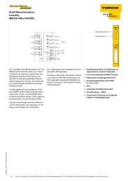
■ A special software (function module)<br />
<strong>for</strong> <strong>in</strong>tegration <strong>in</strong> PLC systems is not required.<br />
■ Cable max. 50 m between <strong>in</strong>terface and<br />
read/write head<br />
■ 3 decimal rotary cod<strong>in</strong>g switches to adjust<br />
the bus address<br />
■ Maximum transmission rate to the fieldbus<br />
120/250/500 kbps<br />
■ Two males 7/8", 5-p<strong>in</strong>, <strong>for</strong> fieldbus connection<br />
■ LEDs <strong>for</strong> display of supply voltage,<br />
group and bus errors as well as status<br />
and diagnostics<br />
■ Connection of up to 4 read/write heads<br />
<strong>via</strong> BL ident M12 extension cables<br />
■ Mixed operation of HF and UHF read/<br />
write heads<br />
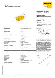
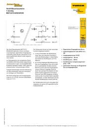
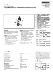
Wir<strong>in</strong>g diagram<br />
DeviceNet IN<br />
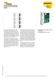
Functional pr<strong>in</strong>ciple<br />
The BL ident® system can be <strong>in</strong>stalled <strong>in</strong><br />
many different ways.<br />
Various fieldbus standards, such as<br />
PROFIBUS-DP, EtherNet/IP, Ethernet Modbus<br />
TCP, EtherCAT, DeviceNet, CANopen and<br />
PROFINET IO allow flexible <strong>in</strong>tegration.<br />
BL ident® <strong>simple</strong> electronic modules<br />
(BL20-2RFID-S, <strong>BL67</strong>-2RFID-S) can be <strong>in</strong>tegrated<br />
<strong>in</strong> exist<strong>in</strong>g control or host systems without<br />
function block, s<strong>in</strong>ce standard <strong>in</strong>put/output<br />
process data is used <strong>for</strong> <strong>communication</strong>.<br />
Programmable gateways with peripheral preprocess<strong>in</strong>g<br />
function relieve the control system<br />
and fieldbus level.<br />
Preassembled sets (2, 4, 6 or 8-port), easily<br />
mounted, available <strong>for</strong> all fieldbus networks.<br />
1 / 5 Hans Turck GmbH & Co.KG ñ D-45472 Mülheim an der Ruhr ñ Witzlebenstraße 7 ñ Tel. 0208 4952-0 ñ Fax 0208 4952-264 ñ more@turck.com ñ www.turck.com
Edition • 2013-05-16T19:40:39+02:00<br />
<strong>Set</strong> <strong>for</strong> <strong>simple</strong> I/O <strong>communication</strong> <strong>via</strong> DeviceNet <strong>in</strong> <strong>IP67</strong><br />
<strong>TI</strong>-<strong>BL67</strong>-DN-S-4<br />
Operat<strong>in</strong>g temperature -40…+70 °C<br />
Storage temperature -40 … +85 °C<br />
Relative humidity 5 to 95% (<strong>in</strong>ternal), Level RH-2, no condensation<br />
(at 45 °C storage)<br />
Vibration test acc. to EN 61131<br />
Extended vibartion resistance<br />
Extended vibartion resistance VN 02-00 and higher<br />
- up to 5 g (at 10 to 150 Hz) For mount<strong>in</strong>g on DIN rail no drill<strong>in</strong>g accord<strong>in</strong>g<br />
to EN 60715, with end bracket<br />
- up to 20 g (at 10 to 150 Hz) For mount<strong>in</strong>g on base plate or mach<strong>in</strong>ery<br />
There<strong>for</strong>e every second module has to be<br />
mounted with two screws each.<br />
Shock test acc. to IEC 68-2-27<br />
Drop and topple acc. to IEC 68-2-31 and free fall to IEC<br />
68-2-32<br />
Electro-magnetic compatibility acc. to EN 61131-2<br />
Protection class <strong>IP67</strong><br />
2 / 5 Hans Turck GmbH & Co.KG ñ D-45472 Mülheim an der Ruhr ñ Witzlebenstraße 7 ñ Tel. 0208 4952-0 ñ Fax 0208 4952-264 ñ more@turck.com ñ www.turck.com
Edition • 2013-05-16T19:40:39+02:00<br />
<strong>Set</strong> <strong>for</strong> <strong>simple</strong> I/O <strong>communication</strong> <strong>via</strong> DeviceNet <strong>in</strong> <strong>IP67</strong><br />
<strong>TI</strong>-<strong>BL67</strong>-DN-S-4<br />
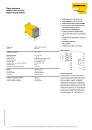
Compatible base modules<br />
Dimension draw<strong>in</strong>g Type P<strong>in</strong> configuration<br />
<strong>BL67</strong>-B-2M12<br />
6827186<br />
2 x M12, 5-pole, female, a-coded<br />
Connectors …/S2500<br />
Connectors …/S2501<br />
Connectors …/S2503<br />
3 / 5 Hans Turck GmbH & Co.KG ñ D-45472 Mülheim an der Ruhr ñ Witzlebenstraße 7 ñ Tel. 0208 4952-0 ñ Fax 0208 4952-264 ñ more@turck.com ñ www.turck.com
Edition • 2013-05-16T19:40:39+02:00<br />
<strong>Set</strong> <strong>for</strong> <strong>simple</strong> I/O <strong>communication</strong> <strong>via</strong> DeviceNet <strong>in</strong> <strong>IP67</strong><br />
<strong>TI</strong>-<strong>BL67</strong>-DN-S-4<br />
LED display<br />
LED color status description<br />
D OFF Error report or diagnostics active.<br />
RED ON Failure of MODBUS <strong>communication</strong> Check if more than 2<br />
adjacent electronic modules are pulled. Relevant modules<br />
are located between gateway and this module.<br />
RED FLASHING (0.5 Hz) Upcom<strong>in</strong>g module diagnostics<br />
RW0 / RW1 OFF No tag, diagnostics disabled<br />
GREEN ON Tag available<br />
GREEN FLASHING (2 Hz) Data exchange with tag enabled<br />
RED ON Read/write head fault<br />
RED FLASHING (2 Hz) Short-circuit <strong>in</strong> the supply l<strong>in</strong>e of read/write head<br />
4 / 5 Hans Turck GmbH & Co.KG ñ D-45472 Mülheim an der Ruhr ñ Witzlebenstraße 7 ñ Tel. 0208 4952-0 ñ Fax 0208 4952-264 ñ more@turck.com ñ www.turck.com
Edition • 2013-05-16T19:40:39+02:00<br />
<strong>Set</strong> <strong>for</strong> <strong>simple</strong> I/O <strong>communication</strong> <strong>via</strong> DeviceNet <strong>in</strong> <strong>IP67</strong><br />
<strong>TI</strong>-<strong>BL67</strong>-DN-S-4<br />
I/O Data Mapp<strong>in</strong>g<br />
INPUT BYTE Bit 7 Bit 6 Bit 5 Bit 4 Bit 3 Bit 2 Bit 1 Bit 0<br />
Channel 0 n DONE BUSY ERROR XCVR CON XCVR ON TP TFR Reserved<br />
n+1 Error Code<br />
n+2 Error Code 1<br />
n+3 Reserved<br />
n+4<br />
n+5<br />
…<br />
n+10<br />
n+11<br />
READ DATA (8 Byte)<br />
Channel 1 n+12 DONE BUSY ERROR XCVR CON XCVR ON TP TFR Reserved<br />
n+13 Error Code<br />
n+14 Error Code 1<br />
n+15 Reserved<br />
n+16<br />
n+17<br />
…<br />
n+22<br />
n+23<br />
READ DATA (8 Byte)<br />
OUTPUT BYTE Bit 7 Bit 6 Bit 5 Bit 4 Bit 3 Bit 2 Bit 1 Bit 0<br />
Channel 0 m XCVR NEXT TAG ID READ WRITE TAG INFO XCVR INFO RESET<br />
m+1 Reserved Byte Count<br />
2<br />
m+2 Address high byte<br />
m+3 Address low byte<br />
m+4<br />
m+5<br />
…<br />
m+10<br />
m+11<br />
WRITE DATA (8 Byte)<br />
Byte Count<br />
1<br />
Byte Count<br />
0<br />
Channel 1 m+12 XCVR NEXT TAG ID READ WRITE TAG INFO XCVR INFO RESET<br />
m+13 Reserved Byte Count<br />
2<br />
m+14 Address high byte<br />
m+15 Address low byte<br />
m+16<br />
m+17<br />
…<br />
m+22<br />
m+23<br />
WRITE DATA (8 Byte)<br />
Byte Count<br />
1<br />
Byte Count<br />
0<br />
5 / 5 Hans Turck GmbH & Co.KG ñ D-45472 Mülheim an der Ruhr ñ Witzlebenstraße 7 ñ Tel. 0208 4952-0 ñ Fax 0208 4952-264 ñ more@turck.com ñ www.turck.com