Pilot's Guide KNS 80 - Shoreline Flying Club
Pilot's Guide KNS 80 - Shoreline Flying Club
Pilot's Guide KNS 80 - Shoreline Flying Club

You also want an ePaper? Increase the reach of your titles
YUMPU automatically turns print PDFs into web optimized ePapers that Google loves.
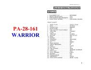
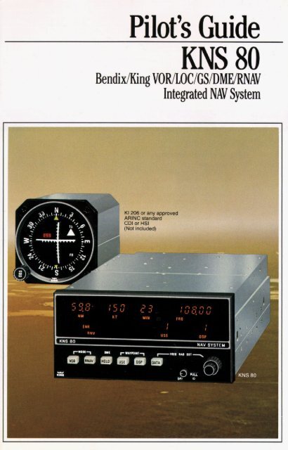
Pilot’s <strong>Guide</strong><br />
<strong>KNS</strong> <strong>80</strong><br />
Bendi x/King VORILOCIGSIDMERNAV<br />
Integrated NAV System
2<br />
Introduction ....................................... 3<br />
<strong>KNS</strong> <strong>80</strong> controls, functions and displays ................<br />
RNAV Review .................................... , ...<br />
What is a waypoint? ..............................<br />
RNAV Geometry ...................................<br />
Linear crosstrack deviation ...................<br />
Variations in along-track distance<br />
while operating in RNAV modes .................. 7<br />
Along Track/Crosstrack error (Chart) ................<br />
<strong>KNS</strong> <strong>80</strong> System applications .......................<br />
How to use the <strong>KNS</strong> <strong>80</strong> ............................... IU<br />
Turn on .......................................... 11<br />
Load waypoint 1 data ............................. 12<br />
Load waypoints 2,3 & 4 data ...................... 14<br />
Takeoff and fly to waypoint 1 ....................... 15<br />
Way point passage ................................<br />
Changeover to next waypoint ...................... , ,<br />
Fly direct to a VORTAC ............................ 17<br />
DME Hold ....................................... 18<br />
RNAV Approach .................................. 19<br />
<strong>KNS</strong> <strong>80</strong> Specifications ........................ Back Cover
c <strong>KNS</strong> <strong>80</strong> )
4<br />
9.-<br />
I-<br />
Battery<br />
compartment<br />
Controls, functions and displays<br />
1 1 1 1 1 1<br />
3. 4. 5. 8. 6. 7.<br />
Numerical displays are 7-segment<br />
gaseous discharge lights. Modes and<br />
operating status information are<br />
annunciated by individually lighted<br />
abbreviations.<br />
The <strong>KNS</strong> <strong>80</strong> illustration above<br />
shows all display legends lighted. In<br />
actual operation, only the appropriate<br />
operating legends will be annunciated.<br />
Using the illustration above as a<br />
reference, they are:<br />
Controls:<br />
1. Power ON/OFF and audio<br />
volume control. Pull out for VOR/LOC<br />
IDENT tone.<br />
2. Data input controls for selection<br />
of VOR/LOC frequency, waypoint radial<br />
and waypoint distance. DME is<br />
automatically tuned with selection of<br />
the paired VOR frequency.<br />
3. VOR is a momentary push<br />
button. Push for conventional<br />
VOR/DME operation. DME is<br />
automatically tuned and distance,<br />
groundspeed and time-to-station (TTS)<br />
to the VORTAC station will be displayed<br />
upon lock on. The Course Deviation<br />
Indicator (CDI) will display conven-<br />
tional angular crosstrack deviation<br />
from your selected course (210"<br />
full scale).<br />
Push VOR again for VOR/PAR<br />
function. Operation will be identical to<br />
VOR/DME operation except the CDI<br />
will display crosstrack deviation 25 nm<br />
full scale from the selected course.<br />
Course width will be constant (linear)<br />
irrespective of distance from VORTAC.<br />
I<br />
1.<br />
- 12.<br />
Depressing VOR cycles between<br />
VOR and VOR/PAR operation.<br />
4. RNAV is a momentary push<br />
button. Push for conventional RNAV<br />
Enroute (RNV/ENR) operation.<br />
Distance, groundspeed and TTS to the<br />
waypoint will be displayed. The CDI will<br />
display a linear crosstrack deviation<br />
*5 nm full scale from selected course<br />
to waypoint.<br />
Push RNAV a ain for RNAV<br />
Approach (RNV/A!R) function.<br />
Operation in RNAV Approach is the<br />
same as RNV/ENR except the CDI will<br />
display crosstrack deviation as 21%<br />
nm full scale. Both provide constant<br />
course width (linear) deviation.<br />
Depressing RNAV cycles between<br />
RNVlENR and RNVIAPR.<br />
5. HOLD is an alternate action<br />
push button. When in the depressed<br />
position, it retains the ori inal DME<br />
frequency (HLD) so DMZoperation<br />
on the original frequency can be<br />
continued while selecting other VOR<br />
or ILS frequencies.<br />
6. DSP is a momentary push<br />
button that selects for display (in order)<br />
any one of four "data storage bins" in<br />
which VOR/LOC frequencies, with or<br />
without waypoint parameters, may be<br />
inserted. Each "storage bin" can be<br />
called up as desired from 1 to 4, then<br />
back to 1.<br />
7. DATA is a momentary push<br />
button that causes either frequency,<br />
waypoint radial or waypoint distance<br />
to be displayed, in that sequence, for
the “data storage bin” (1, 2, 3 or 4)<br />
which is being displayed.<br />
DATA may be used for either<br />
loading data into a “storage bin” or<br />
checking previously loaded data.<br />
8. USE is a momentary push<br />
button that selects the VOR/LOC<br />
frequency and waypoint parameters to<br />
be used for navigation. Pushing USE<br />
transfers the data displayed (DSP) to<br />
“in use” (USE). To “use” a waypoint, it<br />
must first be displayed by means of<br />
DSP. It may then be put into use by<br />
pushing USE. This is a safety<br />
procedure which requires the display<br />
of a frequency and waypoint<br />
parameters prior to actual use.<br />
Anytime USE or DSP is pushed,<br />
frequency (FRQ) will be displayed. This<br />
is a safety feature which forces the<br />
frequency of the facility selected to be<br />
displayed before use. Radial (RAD)<br />
and distance (DST) may subsequently<br />
be displayed by use of the DATA<br />
button:<br />
Displays:<br />
9. Selected function (VOR,<br />
VOR/PAR, RNVIENR, RNV/APR,<br />
HLD, ILS) are annunciated on the<br />
bottom left side of the display area.<br />
10. Distance (NM), groundspeed<br />
(KT) and time-to-station (MIN) to<br />
VORTAC or waypoint are displayed in<br />
the upper left side of the display area.<br />
When the DME is not locked on due to<br />
no DME signal (VOR facility only; failure<br />
of the DME ground station; range<br />
beyond line of sight) or an airborne<br />
DME failure, dashes will appear in<br />
place of numbers.<br />
11. The data selected by the data<br />
input controls is displayed in the upper<br />
right side of the unit. VOR/LOC<br />
frequency (FRQ), waypoint radial<br />
(RAD) and waypoint distance (DST)<br />
are displayed in sequence by<br />
pushing the DATA button. The “data<br />
storage bin” (1 through 4) is selected in<br />
sequence by-pushing the DSP button.<br />
12. The selected “data storage bin”<br />
in use (USE) and the “data storage bin”<br />
being displayed (DSP) are indicated by<br />
the two sets of numbers (from 1 to 4)<br />
disdaved in the lower riaht side of the<br />
display area.<br />
When the “data storaae bin” “in<br />
use” is different from that dsplayed, the<br />
DSP number will flash to indicate that<br />
the system is navigating on data<br />
different from that being displayed.<br />
13. Flag Operation (CDI or HSI)<br />
VOR or ILS Mode: Invalid<br />
VOR/LOC operation is annunciated by<br />
the VOR/LOC flag in the CDI or HSI.<br />
Glideslope flag indicates invalid GS<br />
information. Dashes in the DME display<br />
annunciate invalid DME.<br />
VOR/PAR Mode: VOR/LOC flag<br />
in the CDI or HSI annunciates VOR<br />
and/or DME invalid. Dashes in the DME<br />
display annunciate DME invalid.<br />
RNAV Modes: CDI or HSI flags<br />
same as VOWPAR Mode. Dashes in<br />
distance display annunciate invalid<br />
DME and/or invalid VOR.<br />
Recommended course deviation indicators<br />
The KI 525A is the slaved Pictorial The KI 206 is a VOR/LOC/GS<br />
Navigation Indicator for the KCS 55A<br />
Compass System. It provides a<br />
complete picture of the navigation<br />
situation . . . in VOR/DME, RNAV or ILS<br />
modes. It replaces the Directional Gyro<br />
and CDI in your panel.<br />
Course Deviation Indicator that<br />
provides a rectilinear display of course<br />
deviation in VOWDME, RNAV or ILS<br />
modes.<br />
-<br />
5
6<br />
RNAV Review<br />
Area navigation (RNAV) is a method<br />
of point-to-point navigation along any<br />
desired course within the service area of<br />
a VOR/DME (VORTAC) station, without the<br />
need for flight over the station. This course<br />
is defined by “waypoints”<br />
What is a waypoint?<br />
A waypoint is a predetermined<br />
geographic position located within the<br />
service area of a VORlDME station. It may<br />
be used for route definition and/or progress<br />
reporting. A waypoint is often called a<br />
phantom station because it provides the<br />
same navigation information that a “real”<br />
VOR/DME station at that location would<br />
provide.<br />
A waypoint is defined by its radial and<br />
distance from the selected VORlDME sta-<br />
tion. The waypoint below is located on the<br />
255.0” radial at a distance of 20.0 nautical<br />
miles from ANX VORTAC.<br />
WAVPOINT<br />
VORTAC Staban<br />
I<br />
RNAV Geometry<br />
Waypoint radial, waypoint distance and<br />
crosstrack deviation are supplied by the<br />
RNAV computer as solutions to continuously<br />
changing geometry.<br />
Known inputs to the RNAV computer<br />
are: Waypoint radial (VORTAC station<br />
radial passing through the waypoint).<br />
Waypoht distance from the VORTAC<br />
station.<br />
Aircraft radial from the VORTAC station<br />
to the aircraft.<br />
DME distance from VORTAC station<br />
to the aircraft.<br />
Selected course (OBS) through the<br />
waypoint.<br />
The RNAV computer continuously<br />
processes this information to supply the<br />
aircraft distance from the waypoint and<br />
crosstrack deviation of the aircraft from the<br />
selected course in nautical miles (linear<br />
deviation instead of conventional angular<br />
course deviation).<br />
Linear or angular crosstrack deviation?<br />
Linear crosstrack deviation on CDI or<br />
HSI permits flying parallel to a selected<br />
course by maintaining appropriate needle<br />
deflection In RNAVlENR function each dot<br />
represents one nm off course In RNAVIAPR<br />
function each dot represents 114 nm off<br />
course<br />
In VOR function the RNAV computer IS<br />
by-passed so that deviation from selected<br />
course is conventional angular crosstrack<br />
deviation expressed in degrees off course<br />
(one dot equals 2“)<br />
In VOR/PAR function you have, in<br />
effect, a waypoint located over the VORl<br />
DME station and thus will be provided linear<br />
crosstrack deviation as in RNAV<br />
Linear Crasstrack Deviation
Variations in along-tram aisrance while<br />
operating in RNAV modes<br />
Under certain conditions, VOR scalloping<br />
can contribute significant variation in the<br />
smoothness of the along-track distance<br />
while operating in the RNAV modes<br />
VOR scalloping is defined as<br />
imperfection or deviation in the received<br />
VOR signal which causes radials to deviate<br />
from a standard track VOR scalloping IS<br />
generally the result of reflection from<br />
buildings, terrain or other aircraft This<br />
1.<br />
2.<br />
3* VORTAC<br />
4. D 4<br />
deviation or scalloping effect causes the<br />
CDI needle to slowly or rapidly shift from<br />
side to side<br />
Factors contributing to VOR scalloping<br />
are<br />
the VORTAC (not illustrated). The waypoint<br />
may also be located on the flight path with<br />
the VORTAC behind the aimlane and the<br />
waypoint in front (3).<br />
FLIGHT PATH<br />
When the waypoint offset distance is short, ’ then the acute angle formed by the flight<br />
path and the waypoint offset radial from the<br />
VORTAC to the waypoint can approach<br />
909 (4)<br />
m WAYPOINT<br />
. ..<br />
0 The VORTAC is located in<br />
mountainous terrain and is not a<br />
Doppler VOR<br />
0 Snow cover on the ground around<br />
the VORTAC station<br />
The effects of VOR scalloping are<br />
minimized under the following conditions<br />
C<br />
NT<br />
NT<br />
...... -.,..<br />
Note that, when the angle is large,<br />
the distance needs to be short; con-<br />
versely, when the distance is long, the<br />
angle needs to be small. Another way<br />
of saying this is that the along-track<br />
distance will have the least variation<br />
if the geometry is such that DME<br />
information is the major factor in<br />
computing along-track distance.<br />
7
Legend:<br />
Flightpath<br />
Along Track/Crosstrack Error<br />
Crosstrack (coursewidth) error A Qnm<br />
Along track (distance) error l<br />
WAY POINT 0<br />
This illustration shows the along track and<br />
crosstrack errors that can occur with the RNAV<br />
working with a conventional VORTAC ground<br />
station.
How to interpret the Along<br />
TLacklCrosstrack Error chart<br />
The illustration shows four (4) flight<br />
paths to waypoints being offset varying<br />
distances from the VORTAC. You will<br />
note that in flight path 1 the offset<br />
distance is zero. Or, in other words, the<br />
waypoint is located over the VORTAC.<br />
In this case the along-track and<br />
crosstrack error is minimum. This is<br />
because the along-track error is totally<br />
derived from the DME and the cross-<br />
track error from the VOR.<br />
Please note that the along-track and<br />
crosstrack errors increase in flight<br />
paths 2, 3 and 4, as the waypoint off-<br />
set perpendicular to the flight path<br />
increases. For example, on flight path<br />
4 where the waypoint is offset 100 nm<br />
perpendicular to the flight path and<br />
the aircraft is 100 nm from the way-<br />
point. the aircraft can be anywhere<br />
within a 5.7 nm square when the<br />
crosstrack needle is centered and<br />
the along-track (distance) indicator<br />
is showing exactly 100 nm to go.<br />
In summary, the illustration shows<br />
that the accuracy of the RNAV system<br />
is poorest when the waypoint offset<br />
distance and the aircraft distance from<br />
the VORTAC is large. On the other<br />
hand, the RNAV accuracy is greatest<br />
when the waypoint offset distance and<br />
the distance from the VORTAC is small.<br />
CAUTION: Like all RNAV installations,<br />
each <strong>KNS</strong> <strong>80</strong> installation must be<br />
demonstrated to meet FAA Advisory<br />
Circular 90-45A for IFR approval.<br />
<strong>KNS</strong> <strong>80</strong> System applications<br />
The <strong>KNS</strong> <strong>80</strong> System, in addition<br />
to conventional VOR/DME/ILS<br />
navigation, provides many advantages<br />
related to its RNAV functions:<br />
Direct route navigation from point<br />
of origin to destination without following<br />
the frequently circuitous Victor airways<br />
is a basic use of RNAV. Determine your<br />
most direct route and set up waypoints<br />
at intervals along that route.<br />
(Remember, the <strong>KNS</strong> <strong>80</strong> stores the<br />
frequency of each waypoint. You need<br />
only to change waypoints. Other<br />
systems require you to change<br />
waypoint and VORTAC frequency.)<br />
Location of airfields that are not<br />
equipped with navigation aids is a<br />
common use of RNAV. Locate the<br />
airfield on your navigation chart and<br />
place a waypoint at that location.<br />
Set up a holding pattern at any<br />
geographic point convenient to you or<br />
ATC. Simply establish a waypoint at<br />
that location, then fly your pattern just<br />
as if it were a real VOR station using<br />
your course deviation needle and DME<br />
for reference.<br />
Locate weather breaks reported by<br />
an FSS or controller. Establish a<br />
waypoint at that location and fly directly<br />
to it.<br />
Determine time of ADlZ or<br />
restricted area penetration. Establish a<br />
waypoint at your planned point of<br />
penetration. Fly directly to that<br />
waypoint and you will be provided<br />
continuous distance and time-towaypoint<br />
on your <strong>KNS</strong> <strong>80</strong>.<br />
A route parallel tg an airway may<br />
be established simply by using the<br />
<strong>KNS</strong> <strong>80</strong> in VORlPAR function and<br />
maintaining a constant course<br />
deviation on your CDI (one nm per dot,<br />
up to & 5 nm full scale).<br />
A route parallel to the airway but<br />
farther out may be accomplished by<br />
establishing waypoints the same<br />
distance out from each of the<br />
VORlDME stations that define the<br />
airway.<br />
RNAV charts for RNAV Airway<br />
High Altitude), Approaches. SID’S and<br />
8 TAR’S are available.<br />
9
10<br />
Learnina to use the <strong>KNS</strong> <strong>80</strong> is easv<br />
You can load your VOR/DME<br />
frequencies and RNAV waypoint<br />
information in flight as you proceed<br />
to your destination if you wish and, as<br />
you will see, do it easily<br />
For this demonstration of how to<br />
use the <strong>KNS</strong> <strong>80</strong> we have a flight plan<br />
The wavDoints we have established are:<br />
Waypoint 1. Frequency 114.0 ANX<br />
Radial 255.0"<br />
Distance 20.0 nm<br />
Waypoint 2. Frequency 116.90 SGF<br />
Radial 350.0"<br />
Distance 40.0 nm<br />
Waypoint 3. Frequency 116.90 SGF<br />
Radial <strong>80</strong>"<br />
Distance 39.0 nm<br />
Waypoint 4. Frequency 114.50 ARG<br />
Radial 2<strong>80</strong>"<br />
Distance 14.0 nm<br />
then to Memphis VORTAC 115.5 MEM<br />
from Kansas City direct to Memphis, for<br />
which we have charted our course and<br />
RNAV waypoints We have been<br />
cleared, after takeoff, to hold a 210"<br />
heading until we reach 2,500 ft MSL,<br />
then to Waypoint 1 and direct to<br />
Memphis
- - - - - - -- I 1-1 IZI CI 1-1<br />
I LI -I. -I r-,<br />
L PUN out compartment<br />
to replace batteries<br />
NM KT M#N FRQ<br />
I I I I<br />
ENR 7 7<br />
RNV 11s USE DSP<br />
lhn on the <strong>KNS</strong> <strong>80</strong><br />
1.Turn the system on by rotating the ON/OFF switch clockwise. This<br />
control is also a push-pull switch. The “out” position allows you to<br />
hear VOR/LOC ident tones. The “in” position mutes the ident tones.<br />
When the system is turned ON, the last information being<br />
displayed before previous turn-off will again be displayed.<br />
We see here that following our previous RNV/ENR navigation<br />
on Waypoint 4 we had selected the ILS frequency (109.90) for<br />
approach, landed and turned the system off.<br />
The system will retain all waypoint data (for 4 waypoints)<br />
through a power shutdown. This is made possible through the use<br />
of two internal batteries which may be replaced without removing<br />
the <strong>KNS</strong> <strong>80</strong> from the panel. (See figure 1 above). These batteries<br />
have a nominal life of 2 years.<br />
2. If the batteries should run down, the <strong>KNS</strong> <strong>80</strong> will, upon turn-on,<br />
automatically display a 110.00 frequency, waypoint 1 in USE and<br />
DSR VOR mode, and dashes in the DME display. The unit may then<br />
be operated normally, but will not retain memory when turned<br />
off. (Figure 2.)<br />
N<br />
11
12<br />
<strong>KNS</strong> <strong>80</strong><br />
ENR<br />
RNV USE DIP<br />
Load Waypoint 1 data (114.00 ANX/255.O0/20.0 nm)<br />
3. Put waypoint "1" in the DSP window by depressing the DSP button.<br />
(If there is a "2" in the DSP window initially, you will push the DSP<br />
button three times to go through the 2-3-4-1 sequence to reach "l".)<br />
You will now have waypoint "4" in USE; waypoint "1" in DSF!<br />
The frequency for the old waypoint "l", that is in memory until<br />
changed, is displayed; and there are dashes instead of numbers<br />
in the DME display (showing that a valid DME signal is not being<br />
received). "1" will be flashing, since USE and DSP are not the<br />
same.<br />
<strong>KNS</strong> <strong>80</strong><br />
I 1-1 1-1 1-1<br />
ENR<br />
RNV USE DSP<br />
4.Select your waypoint 1 frequency (1 14.00) using the data<br />
input controls which are the two concentric knobs on the right.<br />
The smaller of the 2 knobs controls the .1 MHz and .05 MHz<br />
digits. The outer knob changes the 1 MHz and 10 MHz digits.<br />
Your selected frequency will appear in the data display<br />
(annunciated "FRQ"), replacing the previous frequency both<br />
in the display and in memory.<br />
Dual <strong>KNS</strong> <strong>80</strong> Operation Caution<br />
When operating dual <strong>KNS</strong> <strong>80</strong>s the respective DMEs may<br />
interfere with each other when the NAV frequencies differ by 5.3<br />
MHz (for example, 108.00 MHz and 113.3 MHz). This interference<br />
results in premature flags or loss of "lock-on.'' Should this occur,<br />
one of the <strong>KNS</strong> <strong>80</strong>s should be either turned off or tuned to a<br />
different NAV frequency so that the 5.3 MHz difference is<br />
eliminated.
5. Select your waypoint 1 radial (255.0”) by first depressing the DATA<br />
button. This will cause the radial for the previous waypoint 1 to<br />
appear in the data display over the annunciation “RAD”. Select<br />
your radial (255.0) with the data input controls. The outer knob<br />
controls the 10” and 100” digits; the center knob “in” position<br />
controls the 1 O digit and the center knob “out” position controls<br />
the 0.1” digit.<br />
6. Select your waypoint 1 distance (20.0 nm) by again depressing<br />
the DATA button, causing display of the previous waypoint 1<br />
distance in the data display over the annunciation “DST”. Select<br />
your distance (20.0 nm) with the data input controls. The outer<br />
knob controls the 10 nm digit, the center knob “in” position<br />
controls.the 1 nm digit and the center knob “out” position controls<br />
the 0.1 nm digit.<br />
Note that throughout this sequence,’the number “1” over DSP<br />
annunciation will blink. It will stop blinking and remain steady only<br />
when the waypoint number in “DSP“ is the same as the waypoint<br />
number in “USE”. This is a safety feature.<br />
That completes selection and storage of all data for<br />
waypoint 1.<br />
13
14<br />
- - - I I 111 1-1 1-1<br />
I I Ll.Ll LC<br />
NM I FRQ<br />
I 1<br />
ENR -1<br />
RNV USE<br />
<strong>KNS</strong> <strong>80</strong> NAV !<br />
c<br />
DSP I<br />
LC id waypoint 2 data (1 16.Su SGF/350.0°/4u.u nm)<br />
7. Put waypoint “2” in the DSP window by depressing the DSP<br />
button. The data display will automatically display the frequency<br />
of the last selected number 2 waypoint and “FRQ” will be<br />
annunciated. All other displays will remain as before.<br />
I RNV USL nem<br />
8.Load waypoint 2 frequency (116.90) using the data input controls<br />
as before. Your selected frequency will replace the previous<br />
frequency in the data display.<br />
,<br />
N i - - M i - , ,IN- 1-~ ~<br />
ENR<br />
RNV USE DSP<br />
..A <strong>80</strong> NAV SYSTEM<br />
9. Load waypoint 2 radial (350.0”) by first pushing the DATA button.<br />
The last selected waypoint 2 radial will be displayed and “RAD”<br />
annunciated. Then select your new waypoint 2 radial using the<br />
data input controls.<br />
I<br />
I
-:-<br />
I I I 7 1-1<br />
-/ l-1. IJ<br />
I<br />
ENR<br />
RNV USE DSP<br />
<strong>KNS</strong> <strong>80</strong> NAV SYSTEM<br />
'-:-. ,-~ , D:, *I<br />
10. Load waypoint 2 distance (40.0 nm) by again pushing the DATA<br />
button. The last selected waypoint 2 distance will appear in the<br />
data display and "DST" annunciated. Then select your new<br />
waypoint 2 distance using the data input controls.<br />
You now have all data for your second waypoint loaded and<br />
in memory. Following the same procedure you may load all four<br />
waypoints.<br />
Remember-you can check or change any RNAV waypoint<br />
data, in any sequence simply by calling up (displaying) that data<br />
using the DSP and DATA buttons. Any displayed data can be<br />
changed by use of the data input controls.<br />
NM MIN<br />
I '-1 1-1 1-1<br />
ENR I I<br />
RNV USE DSP<br />
NAV SYSTEM<br />
Take off and fly to waypoint 1<br />
11. Before takeoff, check to be sure that RNV/ENR is still the active<br />
mode, then depress the DSP button to place waypoint "1" in<br />
the DSP position. Your selected waypoint 1 frequency will<br />
automatically appear in the data display.<br />
You may now want to depress the DATA button to check<br />
radial, and again to check distance in the data display.<br />
Now depress the USE button to place waypoint "1" in the<br />
USE position. The number "1" in the DSP position will stop<br />
blinking, indicating that the displayed data and "in use" data are<br />
the same.<br />
You take off, and as you reach line-of-sight altitude your DME<br />
will lock on. The dashes that were present in the distance display<br />
of the <strong>KNS</strong> <strong>80</strong> will disappear and display distance to<br />
(10)<br />
15
16<br />
waypoint 1. CDI or HSI will also be flagged until both VOR and<br />
DME are valid.<br />
Groundspeed and time-to-station information will not be<br />
accurate unless you are flying directly to or from the VORTAC or<br />
waypoint. You have determined that you want to fly a 112" course<br />
to the first waypoint, so you place 112" under the lubber line on<br />
your CDI (using the OBS knob on the CDI) and fly to center the<br />
needle.<br />
Soon after you are on course direct to waypoint 1, your<br />
groundspeed and TTS will become accurate.<br />
At this time you may also want to check the dent of the VOR<br />
by pulling the ON/OFF/Volume switch to place it in the "out"<br />
position. When satisfied, you can return the switch to the "in"<br />
position and mute the ident tones. DME ident is also available<br />
if connected to your aircraft audio system.<br />
I ENR<br />
Waypoint passage<br />
1-1<br />
u<br />
NM MlN FRQ<br />
I I 1-1 1-1 I-,<br />
I I I, 1-1 r_l<br />
I I<br />
I I<br />
RNV USE DSP<br />
12.You are now passing over waypoint 1. The TO/FROM flag on your<br />
CDI will shift to the FROM position and the needle will hold steady.<br />
If Autopilot coupled to NAV, waypoint passage will be smooth<br />
(wings level).<br />
Your flight plan calls for a course of 132" direct from waypoint<br />
1 to Memphis, so you use your OBS knob to place 132" under the<br />
lubber line, fly to center the needle and continue your flight on the<br />
outbound course from waypoint 1.
Change over to waypoint 2<br />
13. At 30 nm outbound from waypoint 1, you decide to change over to<br />
waypoint 2:<br />
Depress the DSP button and the number 2 will appear<br />
(blinking) over the DSP annunciation and your waypoint 2<br />
frequency will appear in the data display. Your DME display will<br />
not change because waypoint 1 data is still “in use.” At this point,<br />
if you desire, you can recheck your waypoint 2 radial and<br />
distance data in the data display by depressing the DATA button<br />
for each.<br />
When satisfied, depress the USE button to put waypoint 2<br />
data “in use”. The number 2 will appear in the USE annunciated<br />
space; the number 2 in the DSP space will stop blinking.<br />
Waypoint 2 frequency (1 16.90) will automatically appear.<br />
Following VOR/DME receiver acquisition of your new<br />
VORTAC frequency, your distance display will begin reading<br />
distance (NM), groundspeed (KT) and TTS (MIN) to waypoint 2.<br />
Your CDI TO/FROM flag will move to the TO position and you<br />
can continue flying your course directly to waypoint 2.<br />
<strong>Flying</strong> direct to a VOR/DME facility<br />
14. You are approaching waypoint 2 and decide (or are instructed)<br />
to fly direct to Springfield VORTAC.<br />
You are already tuned to 116.90 SGF which is your waypoint<br />
2 frequency, so all you do is depress the VOR button.<br />
CAUTION: When flying directly to or from a<br />
VORTAC facility, it is preferable to select either<br />
the VOR or VOWPAR mode.<br />
17
18<br />
3<br />
c<br />
VOR USE DSP<br />
<strong>KNS</strong> <strong>80</strong> NAV SYSTEM<br />
RNV/ENR disappears from the mode annunciation space on<br />
your <strong>KNS</strong> <strong>80</strong> and VOR appears. The distance display will change<br />
to 42 0 (because it now shows distance to the VORTAC instead of<br />
to the waypoint). Groundspeed (KTS) and time-to-station (MIN)<br />
displays will also change accordingly.<br />
Center the needle on your CDI to show the course direct to<br />
the SGF VORTAC. However, the CDI will display conventional<br />
(angular) crosstrack deviation of +lo" full scale.<br />
PAR L<br />
-<br />
3 CI<br />
VOR USE DSP<br />
<strong>KNS</strong> <strong>80</strong> NAV SYSTEM'<br />
15. Push\the VOR button again and you will have the convenience of<br />
VOR/PAR mode with linear crosstrack deviation displayed on<br />
your CDI as &5 nm full scale (as in RNV/ENR). This permits you to<br />
fly accurately direct to the station or on a parallel course up to 5<br />
nm either side of the direct course.<br />
Tune an ILS frequency without losing DME<br />
16. If you decide to land at Springfield Municipal but want to retain<br />
DME, depress the HOLD button. Now you can select your ILS<br />
frequency (109.90) using the data input controls and checking it in<br />
the data display. HLD will now annunciate. Your distance will<br />
continue to read to the VORTAC and VOR/PAR function will remain<br />
annunciated along with the active ILS function. If you're within<br />
receiving range of the LOC or GS, deviation will appear on the HSI<br />
or CDI.<br />
If you now reselect 116.90, the ILS annunciation will cancel<br />
and you will revert back to VOR/PAR mode. HLD will cancel since
I<br />
1 <strong>KNS</strong>BO<br />
5 -1<br />
PliR r-- c<br />
VDR HLD ILS USE DSP<br />
NAV SYSTEM<br />
VOR and DME frequency are again the same. The DME HOLD<br />
button will remain depressed (it is a two-position button). Thus the<br />
HOLD button functions as a Hold “ARM” when in the “in” position<br />
and actual Hold (HLD) annunciation occurs only when VOR/ILS<br />
and DME frequencies are different.<br />
If you should mistakenly try to use the HOLD function in<br />
RNAV modes, as soon as the frequency is changed the HLD<br />
function will annunciate, DME displays (NM, KT and MIN) will flag<br />
(display dashes) and the CDI or HSI will flag since this is not a<br />
valid RNAV signal. Use of HOLD in VORlPAR mode will result in<br />
a CDI or HSI flag (unless an ILS frequency is selected) and the<br />
DME displays will be to the VORTAC on “HOLD”.<br />
RNAV Approach<br />
17. We have now touched on all modes and operations of the <strong>KNS</strong> <strong>80</strong><br />
except RNAV Approach (RNV/APR).<br />
The RNV/APR mode may be used for runway location (by<br />
placing a waypoint at the approach end of the runway) during an<br />
approach to an airport.<br />
If you are in RNV/ENR mode, depress the RNAV push button<br />
and the RNV/APR mode is immediately activated. In RNV/APR<br />
the deviation needle on your CDI will display crosstrack deviation<br />
as +1Y4 nm full scale, or Y4 nm per dot. All other aspects of the<br />
RNV/APR mode are identical with the RNV/ENR mode.<br />
19
SPLZIFICATIONS<br />
Size: (includinp mounting rack)<br />
Length: 11.19' (28.4 cm), 11.99" (30.5 cm)<br />
with rear connector<br />
Height: 3.0" (7.6 cm)<br />
Width: 6.31 " (16.0 cm)<br />
Weight: 6 Ibs. (2.7 Kg)<br />
Power requirements: 11 to 33 VDC, 25 watts<br />
1.8 A @ 13.75 VDC<br />
.9 A @ 27.50 VDC<br />
Batteries: 2 Silver Oxide Cells (Eveready<br />
303BP or equiv.)<br />
DME Section<br />
Transmitter Power Output: 50 W min. (100 W<br />
tPiC?l)<br />
ensitivity: -82 dbm min. (-85 typical)<br />
Ranae: 0-200 nm<br />
DMEAccuracy 0 to 99 9 nm f 2 nm<br />
displayed to nearest 1 nm<br />
100 to 200 nm 2 3 nm displayed to<br />
nearest nm<br />
NAV Receiver and Converter<br />
Frequency Range 200 channels, 108 00<br />
to 11795<br />
Sensitivity 2 uv Max (hard) will provide a<br />
livable course indication<br />
Selectivity 6 db at f 16 kHz, 65 db at<br />
f 40 kHz<br />
Spurious Responses At least 50 db down<br />
VOR Accuracy Typically less than f 1" error<br />
RNAV Section<br />
Waypoint Distance Selectable on digital<br />
display, zero to 199 9 nm in 1 nm increments<br />
Waypoint Angle Selectable on digital display<br />
in 1" increments<br />
BENDlXtKING<br />
General Aviation Avionics Division<br />
400 North Rogers Road<br />
Olathe, Kansas 66062-1212<br />
Telex 669916 KINGRAD FAX 913-791-1302<br />
Outside USA & Canada (913) 7824700<br />
USA & Canada (913) 782-0400<br />
3/90 006-083G7-oo04 10K hnted in U.S.A.<br />
Allied-Signal Aerospace Company<br />
Bearing and Distance Accuracy: Meets FAA<br />
Advisory Circular 90-45A accuracy<br />
requirements<br />
Course Width:<br />
Function Course Width (+150 ua)<br />
VOR * lo"<br />
VOR Parallel 25nm '<br />
RNAV Eriroute k5nm<br />
RNAV Approach f 1.25 nm<br />
External Outputs<br />
RNAV, ILS, APP External Annunciator:<br />
Active State 0.8 V @ 100 ma<br />
OFF State: High Im edance<br />
OBS Resolver: 30Hz 8B.S resolver meeting<br />
ARlNC requirements<br />
Course Deviation: Up to 5 floating 1,000<br />
Ohm loads<br />
VOR/LOC Warning Flags: Up to 3 floating<br />
1 ,OOO Ohm loads<br />
TOlFROM Indication: Up to 3 floating 200<br />
Ohm loads<br />
DME Audio Output: 18 mw max. into 500 Ohm<br />
(internally adjustable)<br />
NAV Audio Output: 50 mw max. into 500 Ohm<br />
(front panel adjustable)<br />
Glideslope Section<br />
Frequency Range: 40 channel, 329.15 to<br />
335.00 MHz with 150 kHz spacing<br />
Sensitivity: 16 uv (hard) for half flag<br />
Selectivity: >6 db @ f 25 kHz, >40 db @<br />
150 kHz<br />
Number of Deviation Loads: Up to 5 floating<br />
1,OOO Ohm loads