PWR-COBRA-1 RET Antenna System Quick Installation Guide
PWR-COBRA-1 RET Antenna System Quick Installation Guide
PWR-COBRA-1 RET Antenna System Quick Installation Guide
Create successful ePaper yourself
Turn your PDF publications into a flip-book with our unique Google optimized e-Paper software.
639568 • Revision B • April 2008<br />
Page 1 of 6<br />
<strong>PWR</strong>-<strong>COBRA</strong>-1 <strong>RET</strong> <strong>Antenna</strong> <strong>System</strong> <strong>Quick</strong> <strong>Installation</strong> <strong>Guide</strong><br />
Scope<br />
This document briefly describes the installation and operation of the <strong>PWR</strong>-<strong>COBRA</strong> Remote<br />
Electrical Tilt antenna system. It is intended to give an overview of basic installation and<br />
operation for experienced antenna users.<br />
Equipment Required<br />
<strong>COBRA</strong> <strong>RET</strong> capable antennas<br />
<strong>Antenna</strong> mounting hardware (standard or 0–15° mechanical downtilt kit included with<br />
antenna)<br />
Coaxial cables from BTS to antenna RF ports<br />
CBL-<strong>COBRA</strong> one feed line and one jumper per additional antenna, or smart bias tees<br />
and jumper cables. Bias tees eliminate the need for the one main <strong>RET</strong> cable run<br />
<strong>PWR</strong>-<strong>COBRA</strong>-1 interface power supply<br />
RS-232 cable (supplied with <strong>PWR</strong>-<strong>COBRA</strong>-1)<br />
Laptop or computer with <strong>PWR</strong>-<strong>COBRA</strong> software (supplied with <strong>PWR</strong>-<strong>COBRA</strong>-1) installed<br />
<strong>Installation</strong> Instructions<br />
1. Install the antennas using the mounting hardware provided. Record on an <strong>Installation</strong><br />
Configuration sheet the antenna sector, model number, serial number, and pointing angle<br />
from 0–360°.<br />
2. Attach the feed lines from the BTS to the antenna RF ports.<br />
3. Attach the female end of the CBL-<strong>COBRA</strong> homerun data cable to the first antenna<br />
actuator input port. (The homerun cable is the data cable that runs from the base of the<br />
tower to the input of the first antenna in the <strong>RET</strong> system.)<br />
4. Attach the male end of the CBL-<strong>COBRA</strong> jumper line to the output port of the first antenna<br />
and route/connect the female end to the second antenna. Repeat this process until all the<br />
antennas are attached to the <strong>RET</strong> system in a daisy chain configuration. Cap the output<br />
port of the last antenna with the cap cover provided. Please the see note at the end of<br />
this document for cable length recommendations.<br />
5. Attach the male end of CBL-<strong>COBRA</strong> feed line at the base of the tower to the barrel<br />
connector port on the <strong>PWR</strong>-<strong>COBRA</strong>-1 interface power supply.<br />
6. Plug the interface power supply (<strong>PWR</strong>-<strong>COBRA</strong>-1) into the power source.<br />
7. Attach the RS-232 cable (or USB-to-Serial adapter cable) to the laptop or computer and<br />
into the <strong>PWR</strong>-<strong>COBRA</strong>-1 interface power supply.<br />
8. Boot up the laptop or computer and launch the <strong>COBRA</strong> <strong>RET</strong> application software.<br />
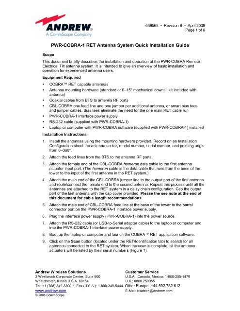
9. Click on the Scan button (located under the <strong>RET</strong>/Identification tab) to search for all<br />
antennas connected to the <strong>RET</strong> system. When the scan is complete, all the antenna<br />
actuators will be listed by their serial numbers (Figure 1).<br />
Andrew Wireless Solutions Customer Service<br />
3 Westbrook Corporate Center, Suite 900 U.S.A., Canada, Mexico: 1-800-255-1479<br />
Westchester, Illinois U.S.A. 60154 U.K.: 0800 250055<br />
Tel: +1 (708) 349-3300 • Fax (U.S.A.): 1-800-349-5444 Other Europe: +44 592 782 612<br />
www.andrew.com E-Mail: bsatech@andrew.com<br />
© 2008 CommScope
Figure 1. <strong>RET</strong> Device Scan Results.<br />
639568 • Revision B • April 2008<br />
Page 2 of 6<br />
10. After the device scan has found all the installed antenna actuators, double click on the<br />
serial number for the antenna actuator in the list that is to be configured.<br />
11. Enter the user level password (the password should be entered using lower case letters)<br />
in the lower section of the screen, and click on Enable. The angle indicator will move to<br />
the current electrical downtilt setting for the antenna. The sector indicator will be blank.<br />
12. Click the Settings tab (located at the top of the screen). At the bottom of the screen, click<br />
on ALL and then click on GET. This will populate the <strong>Antenna</strong> Data section of the screen<br />
with information that was programmed into the antenna at the factory (including model<br />
number, serial number, frequency, gain, and the maximum and minimum tilt settings).<br />
The Operator data section will be blank and should be filled in with the information that<br />
was recorded on the <strong>Installation</strong> Configuration sheet in Step 1 (Figure 2).<br />
Andrew Wireless Solutions Customer Service<br />
3 Westbrook Corporate Center, Suite 900 U.S.A., Canada, Mexico: 1-800-255-1479<br />
Westchester, Illinois U.S.A. 60154 U.K.: 0800 250055<br />
Tel: +1 (708) 349-3300 • Fax (U.S.A.): 1-800-349-5444 Other Europe: +44 592 782 612<br />
www.andrew.com E-Mail: bsatech@andrew.com<br />
© 2008 CommScope
639568 • Revision B • April 2008<br />
Page 3 of 6<br />
Figure 2. Configuring Site Information into the <strong>PWR</strong>-<strong>COBRA</strong> Interface for a <strong>RET</strong> <strong>Antenna</strong>.<br />
13. To store data in the Operator Data fields, use the information gathered during installation<br />
and also enter the <strong>Installation</strong> Date, Installer’s Identification (this can be the company or<br />
the individual name), Base Station ID, Sector, Bearing, and the amount of mechanical<br />
downtilt set on the antenna during the installation. Once this information is entered, click<br />
on SET to save this information to the flash memory at the antenna. Repeat this step for<br />
each antenna located on the tower until all parameters are complete.<br />
14. To set the electrical downtilt for each antenna actuator, first double click on the first<br />
antenna serial number shown in the Vendor/Serial Number box on the Identification<br />
screen. Enter the password (the password should be entered using lower case letters),<br />
and then click on Connect and Enable. The Response window should display<br />
CONNECTED. Select the Settings tab then the AISG tab. Enter the desired downtilt in<br />
the Tilt Setting box at the top, then click the Set button. Repeat this step until all<br />
antennas at the site have the desired electrical downtilt setting. See Figure 2.<br />
Andrew Wireless Solutions Customer Service<br />
3 Westbrook Corporate Center, Suite 900 U.S.A., Canada, Mexico: 1-800-255-1479<br />
Westchester, Illinois U.S.A. 60154 U.K.: 0800 250055<br />
Tel: +1 (708) 349-3300 • Fax (U.S.A.): 1-800-349-5444 Other Europe: +44 592 782 612<br />
www.andrew.com E-Mail: bsatech@andrew.com<br />
© 2008 CommScope
639568 • Revision B • April 2008<br />
Page 4 of 6<br />
15. After all the antenna actuators have been configured and the downtilt settings have been<br />
adjusted to their new values, you may want to generate a record of your work. Go to the<br />
AISG screen shown in Figure 2 to generate a record (a read only XML file will be<br />
generated). Double click on the serial number of the antenna actuator (on the<br />
Identification screen) you want to create a record on, and then click on File located on<br />
the AISG tab screen. The software will prompt you for the location you wish to store the<br />
file on your computer and for a filename. Typically, the file is named after the site the<br />
antennas are installed on (e.g. GA12345 or TX345). After saving this file, you will then<br />
return to the Identification tab where you can repeat this process with the remaining<br />
antenna actuators listed. Each time you click on File you will be asked Do you want to<br />
replace this, click Yes (this will add the new serial number into the file and will start<br />
compiling a list.) Figure 3 shows an example of a file generated using the process<br />
described in this step. These files (XML format) can be opened/viewed through an<br />
Internet browser (Microsoft Internet Explorer).<br />
Figure 3. Site Report File Viewed Using Internet Browser.<br />
Andrew Wireless Solutions Customer Service<br />
3 Westbrook Corporate Center, Suite 900 U.S.A., Canada, Mexico: 1-800-255-1479<br />
Westchester, Illinois U.S.A. 60154 U.K.: 0800 250055<br />
Tel: +1 (708) 349-3300 • Fax (U.S.A.): 1-800-349-5444 Other Europe: +44 592 782 612<br />
www.andrew.com E-Mail: bsatech@andrew.com<br />
© 2008 CommScope
639568 • Revision B • April 2008<br />
Page 5 of 6<br />
To end the session, disconnect the <strong>PWR</strong>-<strong>COBRA</strong>-1 interface power supply from the power<br />
source and its connections to the laptop or computer and <strong>RET</strong> feed line.<br />
The <strong>PWR</strong>-<strong>COBRA</strong>-1 interface power supply can be carried with you to your next <strong>RET</strong><br />
installation site and the procedures outlined above repeated. Future sessions for adjusting<br />
the electrical downtilt settings of antennas will only require that you connect the <strong>PWR</strong>-<br />
<strong>COBRA</strong>-1 interface power supply to the feed line and use the following process:<br />
Scan the site (Step 9).<br />
Double click the antenna serial number to be adjusted (Step 10).<br />
Enter your password (Step 11).<br />
Confirm the sector location (Step 13).<br />
Enter the desired electrical downtilt value (Step 14).<br />
It has also been determined that there is an optimal installation configuration for various types<br />
of <strong>COBRA</strong> equipment.<br />
For a nine MB dual band antenna site, Andrew recommends no more than 170 meters<br />
of total data cabling. For a twelve MB dual band antenna site, we recommend no more<br />
than 130 meters of total data cabling. Multiple homerun cables can be used for very<br />
demanding installations. Note that for 15 inch <strong>COBRA</strong> actuators, Andrew recommends<br />
a homerun cable be used for each sector with a maximum of 3 antennas on a sector.<br />
Andrew Wireless Solutions Customer Service<br />
3 Westbrook Corporate Center, Suite 900 U.S.A., Canada, Mexico: 1-800-255-1479<br />
Westchester, Illinois U.S.A. 60154 U.K.: 0800 250055<br />
Tel: +1 (708) 349-3300 • Fax (U.S.A.): 1-800-349-5444 Other Europe: +44 592 782 612<br />
www.andrew.com E-Mail: bsatech@andrew.com<br />
© 2008 CommScope
SAFETY NOTICE<br />
The installation, maintenance, or removal of an antenna<br />
requires qualified, experienced personnel. Andrew<br />
installation instructions are written for such installation<br />
personnel. <strong>Antenna</strong> systems should be inspected once a<br />
year by qualified personnel to verify proper installation,<br />
maintenance, and condition of equipment.<br />
Andrew disclaims any liability or responsibility for the<br />
results of improper or unsafe installation practices.<br />
Do not install near power<br />
lines. Power lines,<br />
telephone lines, and guy<br />
wires look the same.<br />
Assume any wire or line<br />
can electrocute you.<br />
WARRANTY NOTICE<br />
Proper installation, procedures must be followed when<br />
installing and operating <strong>RET</strong> equipment. Failure to assure<br />
installations are done by properly trained installation<br />
personnel and follow Andrew’s documented procedures<br />
may cause warranty for such products to be void.<br />
Andrew requires that all <strong>RET</strong> installations be pre-tested<br />
and configured prior to installation. Failure to conduct pretest<br />
and pre-installation procedures defined by Andrew will<br />
void warranty.<br />
Do not install on a wet or<br />
windy day or when<br />
lightning or thunder is in<br />
the area. Do not use<br />
metal ladder.<br />
639568 • Revision B • April 2008<br />
Page 6 of 6<br />
Wear shoes with rubber<br />
soles and heels. Wear<br />
protective clothing<br />
including a<br />
long-sleeved shirt and<br />
rubber gloves.<br />
Andrew Wireless Solutions Customer Service<br />
3 Westbrook Corporate Center, Suite 900 U.S.A., Canada, Mexico: 1-800-255-1479<br />
Westchester, Illinois U.S.A. 60154 U.K.: 0800 250055<br />
Tel: +1 (708) 349-3300 • Fax (U.S.A.): 1-800-349-5444 Other Europe: +44 592 782 612<br />
www.andrew.com E-Mail: bsatech@andrew.com<br />
© 2008 CommScope


