Instructions for the installation of the Octagon Display Unit. - Bretford
Instructions for the installation of the Octagon Display Unit. - Bretford
Instructions for the installation of the Octagon Display Unit. - Bretford

You also want an ePaper? Increase the reach of your titles
YUMPU automatically turns print PDFs into web optimized ePapers that Google loves.
<strong>Instructions</strong> <strong>for</strong> <strong>the</strong> <strong>installation</strong><br />
<strong>of</strong> <strong>the</strong> <strong>Octagon</strong> <strong>Display</strong> <strong>Unit</strong>.<br />
These instructions are <strong>for</strong> <strong>the</strong> <strong>Octagon</strong> <strong>Display</strong> unit you have purchased. Because this<br />
product has been specially made <strong>for</strong> you, we have made a prototype and taken some notes<br />
useful to <strong>the</strong> successful <strong>installation</strong> <strong>of</strong> this product.<br />
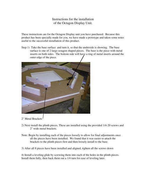
Step 1) Take <strong>the</strong> base surface and turn it, so that <strong>the</strong> underside is showing. The base<br />
surface is one <strong>of</strong> 2 large octagon shaped pieces. The base is <strong>the</strong> piece with metal<br />
inserts on both sides. The bottom side will have a ring <strong>of</strong> metal inserts around <strong>the</strong><br />
outer edge <strong>of</strong> <strong>the</strong> piece.<br />
2" Metal Brackets<br />
2) Next install <strong>the</strong> plinth pieces. These are installed using <strong>the</strong> provided 1/4-20 screws and<br />
2" wide metal brackets.<br />
Note: Begin by installing each <strong>of</strong> <strong>the</strong> pieces loosely to allow <strong>for</strong> final adjustments once<br />
all <strong>the</strong> pieces have been installed. We found that it was easier to attach <strong>the</strong><br />
brackets to <strong>the</strong> plinth pieces first and <strong>the</strong>n loosely install to <strong>the</strong> base.<br />
3) After all 8 pieces have been installed and aligned, tighten all <strong>the</strong> screws down<br />
4) Install a leveling glide by screwing <strong>the</strong>m into each <strong>of</strong> <strong>the</strong> holes in <strong>the</strong> plinth pieces.<br />
Install <strong>the</strong>m fully, <strong>the</strong>n back <strong>the</strong>m out a 1/4 turn <strong>for</strong> ease <strong>of</strong> leveling later.
The unit should now look like this:<br />
5) Turn this unit over and set on <strong>the</strong> ground and level.<br />
Note: Remember, this unit will get very heavy as <strong>the</strong> <strong>installation</strong> progresses. It is much<br />
easier to level <strong>the</strong> unit at this time.<br />
6) Insert 3 wooden dowels into <strong>the</strong> provided holes at each <strong>of</strong> <strong>the</strong> four corners. These<br />
holes are located towards <strong>the</strong> outer edges.<br />
7) Install two <strong>of</strong> <strong>the</strong> 7" wide brackets at each <strong>of</strong> <strong>the</strong> same four corners. Please note <strong>the</strong>
position <strong>of</strong> <strong>the</strong> bracket. The bottom flange should face in towards <strong>the</strong> dowels.<br />
These brackets are installed using <strong>the</strong> provided 10-32 screws. These should also<br />
be loosely installed at first.<br />
The unit should now look like this:<br />
8) The next step is to begin assembling <strong>the</strong> shelving sections, which will be<br />
attached to <strong>the</strong> base later on.<br />
9) Attach <strong>the</strong> top brackets to <strong>the</strong> left and right side pieces. The top bracket is<br />
installed on <strong>the</strong> side with <strong>the</strong> shelf pin holes. The top flange <strong>of</strong> this bracket<br />
should be flush with <strong>the</strong> top <strong>of</strong> <strong>the</strong> panel. These can be fully tightened at this time<br />
10) Attach <strong>the</strong> back panel brackets to <strong>the</strong> back panel. The side flanges should be<br />
flush with <strong>the</strong> edges <strong>of</strong> <strong>the</strong> panel.
Below is a view <strong>of</strong> <strong>the</strong> Back <strong>of</strong> a shelving section:<br />
Below is a view <strong>of</strong> <strong>the</strong> front <strong>of</strong> a shelving section:<br />
Note: At this time, it would be a good idea to move <strong>the</strong> base to <strong>the</strong> exact position<br />
<strong>the</strong> final assembled unit will be located at. Then continue with <strong>the</strong> following<br />
steps.<br />
11) Once all <strong>of</strong> <strong>the</strong> sections have been assembled, position <strong>the</strong>m onto <strong>the</strong> base.
Here is a view with 3 sections installed:<br />
12) Once all <strong>the</strong> sections have been installed an aligned, tighten each unit down<br />
with <strong>the</strong> brackets already installed on <strong>the</strong> base.<br />
13) Next, install <strong>the</strong> slatwall panels by aligning <strong>the</strong> holes in <strong>the</strong> edges with <strong>the</strong><br />
wooden dowels already installed in <strong>the</strong> base. The panels should fall right<br />
into place. If <strong>the</strong>y do not, try and loosen <strong>the</strong> shelving section, install, <strong>the</strong>n<br />
re-secure <strong>the</strong> shelving section.
14) Insert wooden dowels into <strong>the</strong> holes at <strong>the</strong> top <strong>of</strong> <strong>the</strong> slatwall panels. These<br />
will be used to guide <strong>the</strong> top surface into place.<br />
The unit should now look like this:<br />
15) Install <strong>the</strong> top piece using <strong>the</strong> dowels to align it into <strong>the</strong> proper position and<br />
tighten down using <strong>the</strong> provided 10-32 screws and brackets already installed on<br />
<strong>the</strong> shelving sections.<br />
16) Install <strong>the</strong> connecting pins and wooden dowels into <strong>the</strong> holes located towards<br />
<strong>the</strong> central cutout.<br />
Note: <strong>the</strong> wooden Dowels go in <strong>the</strong> larger <strong>of</strong> <strong>the</strong> two holes. The connecting pins<br />
get installed into <strong>the</strong> smaller holes.
18) After <strong>the</strong> pins and dowels have been installed, start installing <strong>the</strong> riser pieces.<br />
The bottoms <strong>of</strong> <strong>the</strong>se riser pieces have two holes on <strong>the</strong> inside surface.<br />
19) Slide <strong>the</strong> risers over <strong>the</strong> dowels and pins. Once all 8 pieces have been<br />
installed, start to secure <strong>the</strong>m with <strong>the</strong> provided black cams by inserting<br />
<strong>the</strong>m into <strong>the</strong> holes on <strong>the</strong> inside surface <strong>of</strong> <strong>the</strong> riser and turning till <strong>the</strong>y<br />
catch. The cams should be installed with <strong>the</strong> arrow pointing downward.<br />
Dowels Connecting Pins<br />
Cams go Here
The unit should now look like this:<br />
20) Install wooden dowels into <strong>the</strong> holes at <strong>the</strong> top <strong>of</strong> each riser piece.<br />
21) Finally Install <strong>the</strong> Top Cap by aligning <strong>the</strong> holes on <strong>the</strong> underside with <strong>the</strong> dowels in<br />
<strong>the</strong> riser and firmly press down <strong>for</strong> a tight fit.<br />
The unit is now complete and should look like this: