scaling parameters for pfbc cyclone separator system ... - circe
scaling parameters for pfbc cyclone separator system ... - circe
scaling parameters for pfbc cyclone separator system ... - circe

You also want an ePaper? Increase the reach of your titles
YUMPU automatically turns print PDFs into web optimized ePapers that Google loves.
SCALING PARAMETERS FOR PFBC CYCLONE SEPARATOR<br />
SYSTEM ANALYSIS<br />
Antonia Gil, Luis M. Romeo and Cristóbal Cortés<br />
CIRCE, Centro de Investigación del Rendimiento de Centrales Eléctricas<br />
Centro Politécnico Superior. María de Luna, 3.<br />
50015 Zaragoza (Spain)<br />
email: antgilma@posta.unizar.es, luismi@posta.unizar.es, tdyfqdb@posta.unizar.es<br />
ABSTRACT<br />
Laboratory-scale cold flow models have been used extensively to study the behaviour<br />
of many installations. In particular, fluidized bed cold flow models have allowed developing<br />
the knowledge of fluidized bed hydrodynamics. In order <strong>for</strong> the results of the research to be<br />
relevant to commercial power plants, cold flow models must be properly scaled.<br />
Many ef<strong>for</strong>ts have been made to understand the per<strong>for</strong>mance of fluidized beds, but up<br />
to now no attention has been paid in developing the knowledge of <strong>cyclone</strong> <strong>separator</strong> <strong>system</strong>s.<br />
CIRCE has worked on the development of <strong>scaling</strong> <strong>parameters</strong> to enable laboratory-scale<br />
equipment operating at room temperature to simulate the per<strong>for</strong>mance of <strong>cyclone</strong> <strong>separator</strong><br />
<strong>system</strong>s. This paper presents the simplified <strong>scaling</strong> <strong>parameters</strong> and experimental comparison<br />
of a <strong>cyclone</strong> <strong>separator</strong> <strong>system</strong> and a cold flow model constructed and based on those<br />
<strong>parameters</strong>. The cold flow model has been used to establish the validity of the <strong>scaling</strong> laws <strong>for</strong><br />
<strong>cyclone</strong> <strong>separator</strong> <strong>system</strong>s and permits detailed room temperature studies (determining the<br />
filtration effects of varying operating <strong>parameters</strong> and <strong>cyclone</strong> design) to be per<strong>for</strong>med in a<br />
rapid and cost effective manner. This valuable and reliable design tool will contribute to a<br />
more rapid and concise understanding of hot gas filtration <strong>system</strong>s based on <strong>cyclone</strong>s.<br />
The study of the behaviour of the cold flow model, including observation and<br />
measurements of flow patters in <strong>cyclone</strong>s and diplegs will allow characterising the<br />
per<strong>for</strong>mance of the full-scale ash removal <strong>system</strong>, establishing safe limits of operation and<br />
testing design improvements.<br />
1
INTRODUCTION<br />
Hot gas cleaning plays an essential role in the development of new power generation<br />
technologies such as Integrated Gasification Combined Cycle (IGCC) or Fluidized Bed<br />
Combustion (FBC). The removal of solid particles from the combustion flue gases is essential<br />
in order to maintain gas turbine working conditions and particle emissions in safe limits. In<br />
particular, in PFBC power stations the entrainment of bed particles may lead to erosion and<br />
fouling in downstream equipment. Special importance is the damage of gas turbine blades. In<br />
addition, fly ash can also produce corrosion due to metal alkali compounds.<br />
Cyclone <strong>separator</strong> <strong>system</strong>s offer nowadays one of the best solution <strong>for</strong> removing<br />
particles from high temperature high pressure installations. Combustion gases from<br />
pressurized beds are an example of this harsh environment, and <strong>cyclone</strong>s are, nowadays, the<br />
only solution commercially available <strong>for</strong> these power stations. These <strong>system</strong>s are simple, low<br />
cost and maintenance with relatively high collection efficiency. Its main disadvantages are the<br />
complex hydraulic behaviour and a efficiency decrease <strong>for</strong> small particles (below 5 μm). In<br />
Escatrón PFBC power plant, the hot gas filtration equipment is a two-stage process per<strong>for</strong>med<br />
in nine streams between the fluidized bed and the gas turbine. The <strong>cyclone</strong>s are high<br />
efficiency, Van Tongeren´s type, with a tangential inlet, cylindrical body, conical base, and an<br />
axial outlet <strong>for</strong> clean gases and outlet port <strong>for</strong> solid particles in the lower part. The solid<br />
extraction bin has been replaced by a dipleg (similar to those found in catalytic cracking) and<br />
a suction nozzle through which collected particles are evacuated along with some amount of<br />
transport gas. In contrast with other devices, such as series of pressure-tight lockhooppers, the<br />
solid extraction by pneumatic conveying improves <strong>cyclone</strong> efficiency and allows reliable<br />
handling and cooling of ash particles with low cost.<br />
Ash and combustion gases exit the pressurized bed at nearly 800 °C and 11 bar(g). The<br />
gas and solid mass flow rates depend on load, coal and sorbent characteristics and other<br />
operating variables, in particular those related with fluidisation. These <strong>parameters</strong> have a<br />
strong influence on the separation efficiency of the <strong>cyclone</strong>s, and there are not well<br />
established theories able to achieve an accurate and complete prediction. Operating<br />
experience at Escatrón have shown sintered deposits and unsteadiness in the dipleg and the<br />
suction nozzle that modify <strong>cyclone</strong> separation efficiency and affect the <strong>cyclone</strong> per<strong>for</strong>mance<br />
and the capacity of ash conveying lines.<br />
The possibility of achieving analyses to establish the influence of different variables in<br />
a real installation is limited due to a non-controlled operating conditions and a lack of data to<br />
2
obtain conclusions. Laboratory-scale cold flow models have been used extensively to study<br />
the behaviour of many installations. In particular, fluidized bed cold flow models have<br />
allowed developing the knowledge of fluidized bed hydrodynamics. In order <strong>for</strong> the results of<br />
these researches to be relevant to commercial power plant, cold flow models have to be<br />
properly scaled. In the present study, <strong>scaling</strong> <strong>parameters</strong> have been developed to build a<br />
dipleg and <strong>cyclone</strong> cold flow model of a PFBC power plant. The cold flow model permits<br />
detailed room temperature studies, such as determining the filtration effects of varying<br />
operating <strong>parameters</strong> and <strong>cyclone</strong> designs.<br />
The study of the behaviour of the cold flow model, including observation and<br />
measurements of flow patterns in <strong>cyclone</strong> and dipleg, will allow characterising the<br />
per<strong>for</strong>mance of the full-scale ash removal <strong>system</strong>, establishing safe limits of operation, testing<br />
design improvements and determining the filtration effects of varying operating <strong>parameters</strong>.<br />
This paper presents the most relevant <strong>scaling</strong> <strong>parameters</strong> <strong>for</strong> a <strong>cyclone</strong> <strong>separator</strong> <strong>system</strong> and<br />
an experimental comparison of a PFBC <strong>cyclone</strong> <strong>separator</strong> <strong>system</strong> and a cold flow model<br />
constructed based on those <strong>parameters</strong>.<br />
CYCLONE SCALING PARAMETERS<br />
Collection efficiency and <strong>cyclone</strong> pressure drop are the most important variables in<br />
<strong>cyclone</strong> behaviour. Criteria <strong>for</strong> <strong>cyclone</strong> <strong>scaling</strong> <strong>parameters</strong>, based on maintain collection<br />
efficiency, have been proposed by several researchers (Cheremisinoff and Cheremisisnoff,<br />
1986; Dirgo and Leith, 1986; Svarovsky, 1981, 1986; Leith and Litch, 1972; Abrahanson et<br />
al., 1978). It is generally assumed the necessity of maintain, at least, Stokes number in order<br />
to maintain collection efficiency. Cheremisinoff and Cheremisinoff (1986) developed the<br />
<strong>scaling</strong> <strong>parameters</strong> by analysing the <strong>for</strong>ces that influence a particle within the <strong>cyclone</strong>. They<br />
proposed to maintain Froude,<br />
ratio between densities and lengths, equation 1.<br />
Fr = gD v , and Reynolds numbers, Re = dvρ<br />
s μ g , and a<br />
2<br />
in<br />
⎛ ⎞<br />
⎜<br />
ρs<br />
D<br />
η = f Fr,<br />
Re, ⎟<br />
(1)<br />
⎜ ⎟<br />
⎝ ρ gd<br />
p ⎠<br />
For the laminar regime of flow (Re
and Stokes numbers. He has developed these <strong>parameters</strong> from the equation <strong>for</strong> accelerated,<br />
three-dimensional particle motion with the main assumption of Stokes regime, equation 2:<br />
Re<br />
p<br />
d pρ<br />
=<br />
μ<br />
g<br />
g<br />
v<br />
r<br />
Other authors only mention the importance of maintaining Stokes number especially at low<br />
solid concentrations (Dirgo and Leith, 1986), or suggest that is the Stokes number the main<br />
variable in <strong>cyclone</strong> efficiency (Svarovsky, 1981; Leith and Licht, 1972). Finally, Chao (1982)<br />
<strong>for</strong> a dilute flow as the freeboard of a PFBC power plant, has suggested as <strong>scaling</strong> <strong>parameters</strong><br />
the Stokes and Froude number and a particle Reynolds number. The last number is necessary<br />
when the flow regime is different from Stokes regime. Although these authors have proposed<br />
different theories <strong>for</strong> <strong>cyclone</strong> <strong>scaling</strong>, none of them has verified their proposals in a real<br />
installation. So, as first approximation <strong>cyclone</strong> behaviour depends on the following variables,<br />
figure 1<br />
< 1<br />
( , ρ , μ , d , V , D,<br />
g,<br />
C )<br />
f g s g p50<br />
in<br />
s _ in<br />
(2)<br />
ρ (3)<br />
Figure 1. Parameters affecting <strong>cyclone</strong> behaviour<br />
Where dp50 has been selected as variable to take into account the particle size distribution at<br />
<strong>cyclone</strong> inlet. Selecting vin, ρg and dp50 as independent variables in order to identify<br />
dimensionless groups:<br />
ΔP<br />
Vin<br />
Cs<br />
ρs<br />
ρg<br />
μg<br />
dp<br />
η<br />
1-η<br />
D<br />
g<br />
4
⎛<br />
⎜<br />
gD ρ g DV<br />
f ,<br />
⎜ 2<br />
⎝V<br />
in μ g<br />
in<br />
2<br />
where = V gD is the Froude number. With the approximation of a flow regime with low<br />
Fr in<br />
relative velocity <strong>for</strong> the particles in the <strong>cyclone</strong> and considering the influence of the<br />
aerodynamic <strong>for</strong>ces by means of the Stokes number (which is a combination of three of the<br />
previous numbers, equation 5).<br />
Stk<br />
Finally, equation (4) is rearranged to read:<br />
,<br />
D<br />
d<br />
p50<br />
ρ<br />
,<br />
ρ<br />
s<br />
g<br />
g<br />
C<br />
,<br />
ρ<br />
s _ in<br />
s<br />
⎞<br />
⎟<br />
⎠<br />
g<br />
(4)<br />
2<br />
2<br />
ρ g DVin<br />
⎛d<br />
p50<br />
⎞ ρ ρ s sd<br />
p50Vin<br />
= ⎜ ⎟ =<br />
(5)<br />
μ<br />
g<br />
⎜<br />
⎝<br />
⎛<br />
⎜<br />
ρ<br />
f Fr,<br />
Re, St,<br />
⎜<br />
⎝ ρ<br />
g<br />
D<br />
⎟<br />
⎠<br />
s s _ in C<br />
,<br />
Froude number takes into account the relation between gravitational and inertia <strong>for</strong>ces.<br />
When particle diameter is small, less than 10 μm, some authors neglect this number due to the<br />
fact that gravitational <strong>for</strong>ces are small compared with inertia <strong>for</strong>ces (Mothes and Löffler,<br />
1985). In our case, more than 80% of the particles are bigger than 10 μm so, it seems<br />
necessary to maintain Froude number.<br />
Reynolds number is not considered to analyse <strong>cyclone</strong> collection efficiency.<br />
Generally, its influence is near negligible due to Reynolds number is high enough. According<br />
to experiments at different temperatures and pressures, from 1 to 6 bars, and from 293 to<br />
1123ºC, Reynolds influence is significant <strong>for</strong> values from 10 3 to 10 5 . The tendency observed<br />
is that Reynolds higher than 10 5 does not influence <strong>cyclone</strong> behaviour (Morweiser and<br />
Bohnet, 1996).<br />
Most of the authors take into account Stokes number to analyse <strong>cyclone</strong> collection<br />
efficiency. Stokes number relates the inertia <strong>for</strong>ces with aerodynamic <strong>for</strong>ces in a flow field.<br />
Stokes number and <strong>cyclone</strong> efficiency are closely related. Generally, researchers consider<br />
laminar flow or assume Stokes´ law (Rep
with Stokes number <strong>for</strong> dp50, but it does not give an exact idea of the PSD conservation. It is<br />
possible to have a wide PSD, and a narrow PSD with the same dp50 and the <strong>cyclone</strong> behaviour<br />
would be completely different. Finally, from a practical point of view, it is impossible to<br />
achieve a scaled PSD. In Escatrón PFBC less than 1% of particles are smaller than 0.4 μm,<br />
that is the limit <strong>for</strong> Rep
<strong>parameters</strong> that were used to calculate the values of the <strong>cyclone</strong> <strong>scaling</strong> <strong>parameters</strong>, and the<br />
dimensions of the 1/5 scaled <strong>cyclone</strong>. The real <strong>cyclone</strong> mean particle diameter, dp50, has been<br />
taken from design data, since to it is not possible to obtain a particle sample from the <strong>cyclone</strong><br />
inlet. Table 2 shows a comparison between the values of the dimensionless <strong>scaling</strong> <strong>parameters</strong><br />
<strong>for</strong> the two <strong>cyclone</strong> <strong>system</strong>s.<br />
Table 1. Comparison between Escatrón PFBC and laboratory cold flow model <strong>parameters</strong> of<br />
the <strong>cyclone</strong> <strong>separator</strong> <strong>system</strong><br />
REAL CYCLONE<br />
SEPARATOR SYSTEM<br />
LABORATORY COLD<br />
FLOW MODEL SYSTEM<br />
D (mm) 1000 200<br />
T (K) 1030 293<br />
P (bar a) 11.14 3.22<br />
μg (kg/m s) 4.25e-5 1.82e-5<br />
ρg (kg/m 3 ) 3.8 3.8<br />
ρs (kg/m 3 ) 2800 2800<br />
dp50 (μm) 40 23<br />
Vin (m/s) 30 13.4<br />
Cs_in (g/m 3 ) 290 290<br />
Mair (kg/s) 10.6 0.19<br />
Mash (g/s) 800 14<br />
Table 2. Comparison of Escatrón PFBC and cold flow dimensionless <strong>scaling</strong> <strong>parameters</strong><br />
Froude number<br />
Reynolds number<br />
Stokes number<br />
Density ratio<br />
REAL CYCLONE<br />
SEPARATOR SYSTEM<br />
LABORATORY COLD<br />
FLOW SYSTEM<br />
2<br />
Fr = vin<br />
gD<br />
91.74 91.79<br />
ρ g Dvin<br />
Re = 2.68 e+6 5.60 e+5<br />
μ<br />
Stk =<br />
d<br />
ρs p<br />
2<br />
50<br />
Solid<br />
concentration ρ s<br />
g<br />
v<br />
in<br />
g<br />
Dμ<br />
g<br />
3.16 5.45<br />
ρ s<br />
736.8 736.8<br />
Cs<br />
_ in<br />
ρ<br />
104 e-6 104 e-6<br />
7
DIPLEG SCALING PARAMETERS<br />
The collected particles removed from the PFBC <strong>cyclone</strong> <strong>system</strong> flow down a dipleg<br />
and are transported by means of pneumatic conveying thought a suction nozzle in the bottom<br />
of the dipleg. There are no specific models of this flow inside the dipleg, so an approximate<br />
analysis, resorting to reasonable and simple models of the physical situation, is appropriate.<br />
Flow patterns inside the dipleg may be expected to possess the following features:<br />
— Particles slid down on the dipleg wall, following a helical path of variable pitch.<br />
— The gas flow generally follows two paths: near the wall, it moves downwards, with<br />
tangential and axial velocity components, whereas it is reversed at the leg core,<br />
<strong>for</strong>ming an upward flow.<br />
As first approximation dipleg behaviour depends on the following variables<br />
( , ρ , , D , L,<br />
V , V , g,<br />
C )<br />
f ρ μ<br />
(7)<br />
g<br />
s<br />
g<br />
In this case, selecting, L, ρg and Vax as independent variables in order to identify<br />
dimensionless groups and rewriting<br />
dl<br />
ax<br />
t<br />
⎛<br />
2 ⎞<br />
⎜<br />
D<br />
ρ<br />
dl ρs Vax<br />
V L gV<br />
ax ax<br />
f , , C<br />
⎟<br />
⎜<br />
sol , , ,<br />
(8)<br />
⎟<br />
⎝ L ρ g Vt<br />
gL μ<br />
⎠<br />
A 1/5 scaled model has been built <strong>for</strong> the dipleg. This factor has been chosen to simulate the<br />
whole PFBC <strong>cyclone</strong> <strong>system</strong>. First dimensionless group is a ratio between dipleg dimensions<br />
and it is maintained. Particle-solid densities ratio is also conserved since it was also a<br />
dimensionless group in <strong>cyclone</strong> <strong>scaling</strong>. Solid concentration as solid- air flow through dipleg<br />
is maintained with the assumption of <strong>cyclone</strong> efficiency is similar. Velocities ratio<br />
dimensionless number is equal to the tangent of the sliding particle velocity. Particles<br />
tangential velocity is supposed to be proportional to the tangential velocity calculated with<br />
Alexander equation (Alexander, 1949):<br />
sol<br />
V r cte<br />
n<br />
t = (9a)<br />
( ) ⎟ ⎟<br />
0.<br />
3<br />
⎛ ⎞ ⎞<br />
0.<br />
14 T<br />
1−<br />
0.<br />
67D<br />
* ⎜ ⎟<br />
⎛<br />
n = 1−<br />
⎜<br />
⎜<br />
dl<br />
(9b)<br />
⎝<br />
⎝283⎠<br />
⎠<br />
Particle axial velocity is proportional to the gas velocity though the dipleg and could be<br />
estimated as<br />
V<br />
m<br />
= (10)<br />
a _ nozzle<br />
ax ρ g Asn<br />
8
The conservation of the transport air flow makes the sliding angle to be conserved. This takes<br />
into account the effects of vortex extending due to suction. This effect could modify the<br />
dipleg flow patterns, so it is important to maintain it constant:<br />
V<br />
V<br />
ax<br />
t<br />
msn<br />
=<br />
ρ A<br />
g<br />
sn<br />
1 ⎛ Ddl<br />
⎜<br />
V ⎝ D<br />
in<br />
⎞<br />
n<br />
⎟<br />
⎠<br />
m<br />
=<br />
m<br />
sn<br />
air<br />
A<br />
A<br />
in<br />
sn<br />
⎛ D<br />
⎜<br />
⎝ D<br />
The small difference in the values of exponent n in Alexander equation modifies slightly the<br />
sliding angle between PFBC <strong>cyclone</strong> and cold flow model. This difference could be estimated<br />
as a 1.6 % and can not be reduced since n depends on the temperature. Froude number is<br />
calculated as a relation between axial velocity, dipleg length and gravity. Because of the<br />
conservation of transport air, Froude number is maintained. Finally, Reynolds number could<br />
not be conserved due to gas viscosity is fixed by the cold flow model temperature.<br />
Table 3 lists the dipleg geometric and operating variables. They have been used to<br />
calculate the dipleg <strong>scaling</strong> <strong>parameters</strong> and dipleg erection. Table 4 summarised the<br />
dimensionless <strong>parameters</strong> of the dipleg, the values of the <strong>scaling</strong> <strong>parameters</strong> were closely<br />
matched between the cold flow model and the Escatrón PFBC except <strong>for</strong> Reynolds number.<br />
Table 3. Comparison between Escatrón PFBC and laboratory dipleg cold flow model<br />
<strong>parameters</strong><br />
dl<br />
n<br />
⎞<br />
⎟<br />
⎠<br />
REAL DIPLEG LABORATORY COLD<br />
FLOW MODEL DIPLEG<br />
Ddl (mm) 400 80<br />
L (m) 9.15 1.83<br />
T (K) 1030 293<br />
P (bar a) 11.14 3.22<br />
ρg (kg/m 3 ) 3.8 3.8<br />
ρs (kg/m 3 ) 2800 2800<br />
Mair (kg/s) 10.6 0.19<br />
Mnozzle (g/s) 163 2.9<br />
Mash (g/s) 800 14.0<br />
(11)<br />
9
Table 4. Comparison of dipleg Escatrón PFBC and cold flow model dimensionless <strong>scaling</strong><br />
Dipleg dimensions<br />
Density ratio<br />
Solid concentration<br />
Velocities ratio<br />
Froude number<br />
Reynolds number<br />
<strong>parameters</strong><br />
ESCATRON PFBC<br />
REAL DIPLEG<br />
LABORATORY COLD<br />
FLOW MODEL DIPLEG<br />
L<br />
Ddl<br />
22.0 22.0<br />
ρ s<br />
ρ<br />
736.8 736.8<br />
g<br />
C =<br />
M<br />
75 e-3 74 e-3<br />
sol<br />
ash<br />
M air<br />
Vax 0.568 0.559<br />
V<br />
t<br />
2<br />
ax<br />
Fr = V gL<br />
105.3 105.4<br />
Lρ<br />
gVax Re =<br />
μ<br />
CYCLONE AND DIPLEG COLD FLOW MODEL<br />
1.96 e+5 4.08 e+4<br />
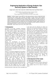
Figure 1 shows <strong>cyclone</strong> and dipleg built with the similarity criteria a<strong>for</strong>ementioned<br />
and have linear dimensions which are one-fifth those of the real PFBC dimensions. Figure 2<br />
shows the cold flow model device that is made up of the following components:<br />
- Two air-pressure supplies: main (L1) and a secondary line (L10) <strong>for</strong><br />
fluidisation of the particle-discharging hopper.<br />
- Pressurized solid storage tank (T1) and variable speed rotary valve connected<br />
to a Venturi nozzle (L3).<br />
- Primary <strong>cyclone</strong> inlet (L4), air with a design solid concentration of 290 g/m 3 .<br />
- Experimental primary <strong>cyclone</strong> (T2), equipped with a PMMA dipleg (T4).<br />
- Secondary <strong>cyclone</strong> (T3) with a solids-collecting bin (T7).<br />
- Two sedimentation chambers with fabric filters <strong>for</strong> complete collection of<br />
particles and cleaning of the exhaust air (T5 and T6).<br />
- Control of airflow by flow meters and valves downstream the sedimentation<br />
chambers (I1 and I2)<br />
10
control<br />
pressure valve<br />
hopper<br />
fluidisation<br />
T P<br />
Pin= 2.21 bar(g)<br />
Tin= 20 °C<br />
ash flow= 50 kg/h<br />
air flow= 680 kg/h<br />
a<br />
Figure 1. Scaled <strong>cyclone</strong> dimensions<br />
b<br />
De<br />
D<br />
B<br />
S<br />
h<br />
H<br />
L<br />
Dimensions<br />
a/D 0.460<br />
b/D 0.203<br />
De/D 0.307<br />
S/D 0.891<br />
h/D 1.310<br />
H/D 3.795<br />
B/D 0.399<br />
L/D 9.022<br />
Figure 2. Laboratory cold flow model <strong>cyclone</strong> <strong>separator</strong> <strong>system</strong><br />
ash<br />
hopper<br />
rotary feeder<br />
P ΔP<br />
primary<br />
<strong>cyclone</strong><br />
ΔP<br />
ash extraction<br />
dipleg<br />
suction<br />
nozzle<br />
.<br />
secondary<br />
<strong>cyclone</strong><br />
T P F<br />
filter 1<br />
T P F<br />
filter 2<br />
clean air<br />
clean air<br />
11
CYCLONE AND DIPLEG EXPERIMENTAL COMPARISON<br />
Experimental <strong>scaling</strong> verification is based on a comparison of pressure drop. Cyclone<br />
pressure drop has a strong influence on collection efficiency. The impossibility to take data of<br />
collection efficiency at PFBC power station to compare with cold flow model has made us to<br />
validate the <strong>scaling</strong> <strong>parameters</strong> based on <strong>cyclone</strong> pressure drop. For pneumatic transport as in<br />
dipleg, pressure drop plays an essential role in its analysis. Probes have been placed in several<br />
points though dipleg, and partial and total dipleg pressure drop have been obtained <strong>for</strong><br />
verification.<br />
The data used in the following <strong>scaling</strong> comparisons were taken at operating conditions<br />
after a periodic overhaul of the Escatrón PFBC, with <strong>cyclone</strong>s revised and cleaned of sintered<br />
deposits. The data used in the <strong>scaling</strong> comparison were taken at a single operating condition<br />
and in steady- state operation. The PFBC power plant load was approximately 90% of the full<br />
load with a standard deviation of 1 MW. Cold flow model pressure drop data were taken<br />
using pressure transducers with a range of 0/62 mbar <strong>for</strong> <strong>cyclone</strong> pressure drop and –62/+62, -<br />
37/+37, -37/+37 and –5/5 mbar <strong>for</strong> dipleg. The data from Escatrón PFBC were obtained with<br />
pressure transducer with a range of 0/490 mbar <strong>for</strong> <strong>cyclone</strong> pressure drop, ad –98/+98 mbar<br />
<strong>for</strong> dipleg pressure drop. Data uncertainty is about 0.4% of span.<br />
PFBC <strong>cyclone</strong> pressure drop transducers are installed in five of the nine <strong>cyclone</strong>s.<br />
Data from pressure drop varies from a maximum of 199.2 mbar to a minimum of 141.0 mbar.<br />
Table 5 shows the PFBC data and its comparison with cold flow model data.<br />
PFBC pressure drop data shows discrepancies between real <strong>cyclone</strong>s. Most probably, a<br />
combination of ashes and gases non-homogeneity at <strong>cyclone</strong> inlet could cause these<br />
discrepancies. Another cause to explain this effect is <strong>cyclone</strong> fouling. As it will be proved in a<br />
next paper (Romeo et al., 1999), fouling causes a reduction in <strong>cyclone</strong> pressure drop. A<br />
different fouling between <strong>cyclone</strong>s could be the cause of discrepancies in real data.<br />
In order to compare and validate the cold flow model, it is necessary to scale down the<br />
Escatrón PFBC <strong>cyclone</strong> pressure drop data or scale up the cold flow model data. The<br />
dimensionless variable <strong>for</strong> the pressure drop is<br />
⎛ C ⎞<br />
Δ P ⎜<br />
ρs<br />
s _in<br />
=<br />
⎟<br />
2 f Fr , ,<br />
(12)<br />
1 ρV<br />
⎜ ⎟<br />
2 in ⎝<br />
ρ g ρs<br />
⎠<br />
The right-hand term of the equation (12) is conserved due to the maintenance of<br />
dimensionless numbers that affect <strong>cyclone</strong> behaviour. So, to scale pressure drop data it is<br />
12
necessary take in account the velocity ratio to the power of two, it means to operate by a<br />
factor of five.<br />
The agreement between Escatrón PFBC pressure drop data and cold flow model data<br />
scaled up is excellent, as indicated in table 5. For the PFBC <strong>cyclone</strong>s, the pressure drop has an<br />
average of 168.0 mbar and a standard deviation of 20.3 mbar, the 99% of the data would be in<br />
the range of 127.4/208.6 mbar. In the cold flow model, the average is 148.5 mbar with a<br />
standard deviation of 9.0 mbar, so the 99% of the data would be in the range of 124.0/166.5<br />
mbar. The latter range of data is approximately inside the <strong>for</strong>mer one. This agreement<br />
provides a verification of the <strong>scaling</strong> proposed above.<br />
Table 5. Comparison between PFBC and cold flow model <strong>cyclone</strong> pressure drop data<br />
Cyclone 1<br />
Cyclone 3<br />
Cyclone 5<br />
Cyclone 7<br />
Cyclone 9<br />
Average of five PFBC<br />
Cyclones<br />
Cold flow Model<br />
Cyclone<br />
Cold flow Model<br />
Cyclone Scaled data<br />
Maximum Minimum Average<br />
191.4<br />
199.2<br />
174.9<br />
150.8<br />
145.4<br />
175.7<br />
190.3<br />
167.7<br />
142.9<br />
141.0<br />
182.5<br />
194.7<br />
172.3<br />
147.7<br />
143.1<br />
Standard<br />
deviation<br />
7.00<br />
3.83<br />
2.95<br />
2.89<br />
1.72<br />
194.7 143.1 168.0 20.5<br />
34.43 24.06 29.73 1.79<br />
172.2 120.3 148.5 9.0<br />
Tables 6 and 7 show also a comparison between PFBC and cold flow model dipleg<br />
pressure drop data. Three zones are observed in the dipleg, an upper one where the pressure<br />
drops strongly. An intermediate region where the pressure drop is negative and particles are<br />
going down vertically. Finally, the last zone near the suction nozzle where the pressure drops<br />
due to pneumatic transport. These three zones are observed both, in the PFBC and the cold<br />
flow model, so that qualitatively the behaviour or the diplegs are similar, although a<br />
difference in values is also observed. Table 6 shows the data at real and cold flow model<br />
dipleg.<br />
13
Table 6. Comparison between PFBC and cold flow model dipleg pressure drop data<br />
PFBC dipleg pressure drop 1<br />
PFBC dipleg pressure drop 2<br />
PFBC dipleg pressure drop 3<br />
Cold flow model dipleg pressure drop 1<br />
Cold flow model dipleg pressure drop 2<br />
Cold flow model dipleg pressure drop 3<br />
Maximum Minimum Average<br />
63.2<br />
- 3.44<br />
22.3<br />
60.6<br />
- 4.94<br />
16.3<br />
61.8<br />
- 3.94<br />
18.1<br />
2.50<br />
- 0.18<br />
Standard<br />
deviation<br />
In table 7 the scaled data <strong>for</strong> the cold flow model is compared with real data. Scaling<br />
up has been done in the same manner as <strong>cyclone</strong> <strong>scaling</strong> up, i.e. the velocity ratio to the power<br />
of two. In spite of the similar tendencies in pressure drop, the <strong>scaling</strong> is not as good as the<br />
<strong>cyclone</strong> <strong>scaling</strong>. In this case the effect of varying Reynolds number is affecting the agreement.<br />
Taking into account the Reynolds influence and multiplying by 5 (PFBC and cold flow model<br />
Reynolds relation) the agreement of pressure drop in the two upper zones is excellent.<br />
Possibly, a combination of suction and ash deposition is the responsible of discrepancies in<br />
the lower zone pressure drop data. In addition, the effect of fluidisation air in PFBC dipleg<br />
bottom has not been taken into account in the cold flow model constructed, and it could<br />
modify the measurements or the behaviour in this zone. Further studies are necessary to<br />
explain this discrepancy.<br />
Table 7. Comparison between PFBC and cold flow model dipleg pressure drop data<br />
Pressure drop 1<br />
Pressure drop 2<br />
Pressure drop 3<br />
PFBC data Cold flow model<br />
61.8<br />
- 3.94<br />
18.1<br />
data<br />
2.50<br />
- 0.18<br />
0.04<br />
Scaled data<br />
12.5<br />
- 0.9<br />
0.2<br />
0.04<br />
1.02<br />
0.54<br />
2.31<br />
Scaled data and<br />
Reynolds<br />
influence<br />
62.5<br />
- 4.5<br />
1.0<br />
14
CONCLUSIONS<br />
A 1/5-scale model of the Escatrón PFBC <strong>cyclone</strong> <strong>system</strong> has been constructed based<br />
on <strong>scaling</strong> <strong>parameters</strong>. Comparisons of <strong>cyclone</strong> pressure drop from the cold flow model and<br />
Escatrón PFBC indicates that the <strong>cyclone</strong> behaviour of the two <strong>cyclone</strong>s is similar. Because of<br />
<strong>cyclone</strong> pressure drop is one of the most important <strong>parameters</strong> in collection efficiency, it is<br />
assumed the <strong>cyclone</strong> efficiency would be maintained in both <strong>system</strong>s. This point remains<br />
open due to the impossibility to validate the cold flow model results at the real <strong>system</strong>.<br />
An analysis of the main variables in PFBC <strong>cyclone</strong> dipleg has been done. This study<br />
has not been addressed be<strong>for</strong>e. It has been impossible to maintain all the <strong>scaling</strong> <strong>parameters</strong><br />
that influence dipleg behaviour. Reynolds number has not been maintained due to <strong>cyclone</strong><br />
<strong>scaling</strong> determinate the value of some variables in dipleg behaviour. Reynolds influence has<br />
been taken into account to validate the cold flow model data. Comparison of dipleg pressure<br />
drop from the cold flow model and Escatrón PFBC show a good agreement through the<br />
dipleg. In the suction nozzle some discrepancies has been observed. The reason <strong>for</strong> these<br />
discrepancies could be the different behaviour of the ash conveying lines in Escatrón PFBC<br />
and the sedimentation chamber in the cold flow model. Further studies are needed to fully<br />
understand fluid flow around suction nozzle.<br />
The cold flow model is revealed as an important tool to optimize and understand the<br />
<strong>cyclone</strong> <strong>system</strong> behaviour. It is also useful to know the influence of different operational<br />
variables. At present, these studies are being carried out.<br />
ACKNOWLEDGEMENTS<br />
This research has been fully supported by ENDESA, S.A. Mr Alfonso Ruiz, director<br />
of Escatrón PFBC power station, Dr. Emilio Menéndez, head of the R&D department of<br />
ENDESA, S.A., and Mr. Diego Martínez, head of the R&D department at Escatrón are<br />
gratefully acknowledged <strong>for</strong> making possible the project and <strong>for</strong> all the facilities provided.<br />
Escatrón power plant personnel are also acknowledged <strong>for</strong> their useful assistance.<br />
NOMENCLATURE<br />
Asn<br />
Cs_in<br />
Csol<br />
suction nozzle area (m 2 )<br />
solid concentration at <strong>cyclone</strong> inlet (g/m 3 )<br />
solid concentration at dipleg (g/m 3 )<br />
D <strong>cyclone</strong> diameter (m)<br />
15
Ddl<br />
dp<br />
dp50<br />
dipleg diameter (m)<br />
particle diameter (m)<br />
particle diameter at 50% of the PSD (m)<br />
Fr Froude number<br />
g gravity acceleration (m/s 2 )<br />
L dipleg length (m)<br />
ma_nozzle<br />
Mair<br />
Mash<br />
P pressure (bar)<br />
air flow through the suction nozzle (g/s)<br />
air flow at <strong>cyclone</strong> inlet (kg/s)<br />
ash flow at <strong>cyclone</strong> inlet (kg/s)<br />
Re Reynolds number<br />
Rep<br />
particle Reynolds number<br />
Stk Stokes number<br />
T temperature (K)<br />
Vax<br />
Vin<br />
vr<br />
Vt<br />
Greek Leters<br />
axial velocity at dipleg (m/s)<br />
inlet <strong>cyclone</strong> velocity (m/s)<br />
relative velocity (m/s)<br />
tangential velocity at dipleg (m/s)<br />
η <strong>cyclone</strong> efficiency (%)<br />
ρg<br />
μg<br />
ρs<br />
REFERENCES<br />
gas density (kg/m 3 )<br />
gas viscosity (kg/m s)<br />
solid density (kg/m 3 )<br />
Abrahamson J, Martin CG, Wong KK (1978) The Physical Mechanisms of Dust<br />
Collection in a Cyclone. Transactions of the Institute of Chemical Engineers, Vol. 56, pp.168-<br />
177.<br />
Alexander R (1949) Fundamentals of Cyclone Design and Operation. Procedures of<br />
the Australian Institute Min. Metall, nº 152, pp.203-208.<br />
Chao BT (1982) Scaling and Modelling. Handbook of Multiphase Systems. Edited by<br />
Gad Hetsroni, Hemisphere Publishing Co, pp.(3)44-(3)48<br />
16
Cheremisinoff NP, Cheremisinoff PN (1986) Particulate Capture from Process Gas<br />
Streams in Encyclopedia of Fluid Mechanics, edited by Cheremisinoff NP, Vol. 4, pp. 1217-<br />
1279<br />
Dirgo J, Leith D (1986). Design of Cyclone Separators in Encyclopedia of Fluid<br />
Mechanics, edited by Cheremisinoff NP, Vol. 4, pp.1281-1306<br />
Hoffman AC, Arends H, Sie H (1991) An Experimental Investigation Elucidating the<br />
Nature of the Effect of Solids Loading on Cyclone Per<strong>for</strong>mance. Proceedings of the Filtration<br />
Society, Filtration & Separation, Vol. 2, pp.188-193<br />
Hoffman AC, van Santen A, Allen RWK, Clift R (1992) Effects of Geometry and<br />
Solid Loading on the Per<strong>for</strong>mance of Gas Cyclones. Powder Technology, Num. 70, pp.83-91.<br />
Leith D, Litch W (1972) The Collection Efficiency of Cyclone Type Particle<br />
Collectors. A New Theoretical Approach. Air Pollution and Its Control, AIChE Symposium<br />
Series, Num.26, Vol.68, pp.196-206<br />
Morweiser and Bohnet (1996) Influence of Temperature and pressure on Separation<br />
Efficiency and Pressure Drop of Aero<strong>cyclone</strong>s in High Temperature Gas Cleaning, edited by<br />
E.Schmidt. Institut für Mechanishe Verfahrenstechnik und Mechanik.<br />
Mothes H, Löffler R (1985) Motion and Deposition of Particles in Cyclones. German<br />
Chemical Engineering, Num.8, pp.223-233<br />
Romeo LM, Gil A, Cortés C (1999) Improving Hot Gas Filtration Behaviour in PFBC<br />
Power Plants. Paper accepted to be presented at 15 th International FBC Conferences<br />
Svarovsky L (1981) Solid Gas Separation in Handbook of Powder Technology, edited<br />
by Elsevier ,Vol 3, pp.33-52<br />
Svarovsky L (1986) Solid-Gas Separation in Gas Fluidization Technology, edited by<br />
Geldart D, John Wiley & Sons, pp.197-217<br />
Wheeldon JM, Burnard GK (1987) Per<strong>for</strong>mance of Cyclones in the Off-Gas Path of a<br />
Pressurized Fluidized Bed Combustor. Proceedings of the Filtration Society, Filtration &<br />
Separation, Vol. 3, pp.178-187<br />
17