Presentation - Virtual Inductor Library: a new inductor design approach
Presentation - Virtual Inductor Library: a new inductor design approach
Presentation - Virtual Inductor Library: a new inductor design approach
Create successful ePaper yourself
Turn your PDF publications into a flip-book with our unique Google optimized e-Paper software.
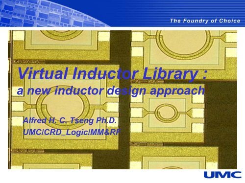
<strong>Virtual</strong> <strong>Inductor</strong> <strong>Library</strong> :<br />
a <strong>new</strong> <strong>inductor</strong> <strong>design</strong> <strong>approach</strong><br />
Alfred H. C. Tseng Ph.D.<br />
UMC/CRD_Logic/MM&RF
Outline<br />
� <strong>Virtual</strong> <strong>Inductor</strong> <strong>Library</strong> Implementation by<br />
EM Design Methodology (EMDM)<br />
� Results and Comparison<br />
� Other Applications by using EMDM<br />
� Conclusions<br />
2
How to Do <strong>Inductor</strong> Design ?<br />
� At first, referenced to foundry’s measured<br />
<strong>inductor</strong> library and scalable model library.<br />
� Designers iterate the following processes:<br />
� Designing test structures<br />
� Wafer processing<br />
� Measuring data<br />
� Modeling<br />
� If not satisfied, do again …<br />
“Time Time and Money are losing”<br />
losing<br />
3
UMC’s Innovative Approach<br />
- EM Design Methodology (EMDM)<br />
� In addition to existed measured and<br />
scalable model library.<br />
� We provide some extra features:<br />
� This “methodology” is to generate a process<br />
related information for EM simulator, then<br />
customers can <strong>design</strong> their own innovative<br />
<strong>inductor</strong>s with fast; accurate; and low-cost<br />
features.<br />
� Save prototype & test cycle-time.<br />
� Reduce R&D cost.<br />
4
UMC’s EMDM<br />
- What is our <strong>approach</strong> ?<br />
� General <strong>Inductor</strong> Design<br />
With real Si measured data<br />
3-D EM simulation data<br />
+ RF SPICE model<br />
3-D EM simulation to interpolate,<br />
then to output S-parameter<br />
3-D EM simulation to extrapolate,<br />
then to output S-parameter<br />
Parameter 2<br />
<strong>Inductor</strong> Pool<br />
Parameter 1<br />
*** Parameters : Di; W; S & N<br />
5
UMC’s EMDM<br />
- What is our <strong>approach</strong> ?<br />
�Customer’s Special <strong>Inductor</strong> Design<br />
Novel <strong>Inductor</strong><br />
Design<br />
Pattern ground<br />
shielding<br />
3-D EM<br />
Simulation<br />
Transformer or Stacked<br />
S-Parameter Designer<br />
6
UMC’s EMDM: Work Flow<br />
Working Flow<br />
UMC Process<br />
Technology profile<br />
SiO2<br />
Si<br />
M3<br />
M1<br />
M2<br />
2<br />
ε<br />
Testkey Layout<br />
Wafer<br />
Fabrication<br />
ICCAP<br />
Parameter Extraction<br />
3-D EM Simulation Circuit Simulation<br />
S-Parameter<br />
Ansoft HFSS<br />
Ansoft Designer<br />
7<br />
RF SPICE<br />
Model
UMC’s EMDM<br />
- What is the technology file?<br />
ε r<br />
ε r<br />
ε r<br />
ε r<br />
Conductivity<br />
Passivation<br />
Thickness<br />
M6 Thickness<br />
SiO 2 Thickness<br />
M5 Thickness<br />
SiO 2 Thickness<br />
Silicon<br />
Thickness<br />
Last Metal<br />
Second Top Metal<br />
8
UMC’s EMDM<br />
- What is the technology file?<br />
Material Physic Param Source<br />
Substrate T.K, Rs EDR<br />
STI T.K, Dielectrics EDR<br />
M1~6 T.K, Rs EDR<br />
ILD/IMD1~5 T.K, Dielectrics EDR<br />
Passivation T.K, Dielectrics EDR<br />
*** This unique technology file has been proved by comparing<br />
the simulation data with real silicon measured data.<br />
9
EMDM’s <strong>Inductor</strong> Design Flow<br />
All you need is to input geometric parameters:<br />
N Turns<br />
D Diameter<br />
W Width<br />
S Spacing<br />
T Top Metal thickness<br />
Seg Segments (ex. Octagonal, Circular)<br />
“A A friendly interface to <strong>design</strong>ers.”<br />
<strong>design</strong>ers.<br />
10
<strong>Virtual</strong> <strong>Inductor</strong> <strong>Library</strong> by EMDM<br />
� For general <strong>inductor</strong> <strong>design</strong>, both real Si<br />
measurement data and 3D EM simulation data are<br />
used for the model extraction.<br />
� Since combining these two groups of raw data, we<br />
can extract RF SPICE model with higher accuracy.<br />
� This unique technology file can be faithfully<br />
represented Si process parameters.<br />
� Based on this calibrated technology file, <strong>design</strong>ers<br />
can implement their novel ideas, then obtain Sparameter<br />
for circuit simulation.<br />
11
Ansoft HFSS<br />
� Current version 9.0.<br />
� A true 3D electromagnetic-based <strong>design</strong><br />
tool.<br />
� Widely used in package; wave guide; and<br />
antenna.<br />
� UMC is the first foundry that provide the<br />
methodology for using 3D EM <strong>design</strong> tool to<br />
support RFIC <strong>design</strong>.<br />
12
EMDM Implement in Ansoft Tools<br />
Virtuoso<br />
AnsoftLink<br />
ACIS<br />
GDSII<br />
DXF<br />
Macros<br />
UMC<br />
Technology<br />
File<br />
Ansoft HFSS<br />
Ansoft Designer<br />
Inductance<br />
Quality Factor<br />
Self-Resonance<br />
etc<br />
13<br />
Matrix Parameters<br />
S-, Y-, Z-<br />
Power Plug-in
AnsoftLink for Virtuoso<br />
Easier than<br />
“Cut & Paste”<br />
14
Ansoft Designer<br />
15
Number of Turns<br />
– L & Q Comparison (1)<br />
Quality Factor<br />
10<br />
8<br />
6<br />
4<br />
2<br />
0<br />
-2<br />
-4<br />
0.18-micro 1P6M <strong>Inductor</strong> N=5.5 comparison<br />
N5.5_s_Q<br />
N5.5_m_Q<br />
N5.5_s_L<br />
N5.5_m_L<br />
0 1 10 100<br />
Frequency[GHz]<br />
� Width= 10µm, Spacing= 2µm, Di= 85µm, Turns= 5.5, Al= 20KA<br />
14<br />
12<br />
10<br />
8<br />
6<br />
4<br />
2<br />
0<br />
Inductance[nH]<br />
16
Number of Turns<br />
– L & Q Comparison (2)<br />
Quality Factor<br />
10<br />
8<br />
6<br />
4<br />
2<br />
0<br />
-2<br />
-4<br />
0.18-micro 1P6M <strong>Inductor</strong> N=4.5 comparison<br />
N4.5_s_Q<br />
N4.5_m_Q<br />
N4.5_s_L<br />
N4.5_m_L<br />
0 1 10 100<br />
Frequency[GHz]<br />
� Width= 10µm, Spacing= 2µm, Di= 85µm, Turns= 4.5, Al= 20KA<br />
14<br />
12<br />
10<br />
8<br />
6<br />
4<br />
2<br />
0<br />
Inductance[nH]<br />
17
Inner Diameter – L Comparison<br />
Inductance[nH]<br />
10<br />
9<br />
8<br />
7<br />
6<br />
5<br />
4<br />
3<br />
2<br />
1<br />
0<br />
-1<br />
0.18-micro 1P6M Inductance/diff diameter<br />
comparison<br />
D150_s_L<br />
D 85_s_L<br />
D150_m_L<br />
D 85_m_L<br />
D230_s_L<br />
D230_m_L<br />
0 1 10 100<br />
Frequency[GHz]<br />
� Fixed width= 15µm, Spacing= 2µm, Turns= 2.5 & Al= 20KA,<br />
Split Di: 85µm, 150µm and 230µm<br />
18
Increasing Metal Thickness (Al 30kA)<br />
- L & Q Comparison<br />
Quality Factor<br />
12<br />
10<br />
8<br />
6<br />
4<br />
2<br />
0<br />
-2<br />
-4<br />
-6<br />
0.18-micro 1P6M <strong>Inductor</strong> Case2 comparison<br />
Q_simulation<br />
Q_measurement<br />
L_simulation<br />
L_measurement<br />
0 1 10 100<br />
Frequency[GHz]<br />
� Width= 15µm, Spacing= 2µm, Di= 210µm, Turns= 5.5, Al= 30KA<br />
30<br />
27<br />
24<br />
21<br />
18<br />
15<br />
12<br />
9<br />
6<br />
3<br />
Inductance[nH]<br />
19
Pattern Ground Shielding – Deep Trench (1)<br />
4.0um<br />
� Using trench to reduce substrate loss.<br />
20
Pattern Ground Shielding – Deep Trench (2)<br />
Quality Factor<br />
16<br />
14<br />
12<br />
10<br />
8<br />
6<br />
4<br />
2<br />
0<br />
-2<br />
-4<br />
0.18-micro 1P6M <strong>Inductor</strong> with Deeptrench<br />
comparison<br />
DT_s_Q<br />
DT_m_Q<br />
DT_s_L<br />
DT_m_L<br />
0 1 10 100<br />
Frequency[GHz]<br />
� Width= 15µm, Spacing= 2µm, Di= 202µm, Turns= 5.5, Al= 30KA<br />
� With 4.0um deep trench PGS<br />
10<br />
9<br />
8<br />
7<br />
6<br />
5<br />
4<br />
3<br />
2<br />
1<br />
0<br />
Inductance[nH]<br />
21
Other Applications by EDDM<br />
� Interconnect RF model extraction<br />
� Cross talk analysis in RF or high speed<br />
digital IC<br />
� Capacitor: MIM or MOM (fringing)<br />
� Internal antenna <strong>design</strong><br />
� Package modeling for IC <strong>design</strong><br />
22
Conclusions<br />
� Customer’s success is always our first priority.<br />
� UMC RF technology/<strong>design</strong> support is enhanced by<br />
providing an accurate and efficient methodology for<br />
<strong>inductor</strong> <strong>design</strong>.<br />
� EMDM can be extended to other applications in<br />
high frequency analysis.<br />
� Reducing development cycle-time and cost,<br />
customers can go into production much faster.<br />
� UMC is always seeking better and improved<br />
service for our customers.<br />
23
Please Fill Out the<br />
Survey Questionnaire<br />
Contact persons in UMC:<br />
H_C_Tseng@umc.com<br />
Bigchoug_Hung@umc.com<br />
24


