MultiBox - antrax.de
MultiBox - antrax.de
MultiBox - antrax.de

You also want an ePaper? Increase the reach of your titles
YUMPU automatically turns print PDFs into web optimized ePapers that Google loves.
<strong>antrax</strong> Datentechnik GmbH<br />
info@<strong>antrax</strong>.<strong>de</strong> - www.<strong>antrax</strong>.<strong>de</strong><br />
Manual<br />
18.10.2005<br />
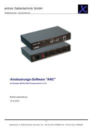
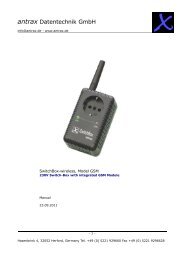
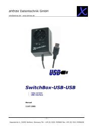
<strong>MultiBox</strong><br />
• programmable sequence control<br />
• master-slave function<br />
• watchdog function<br />
• integrated control panel<br />
• interface: USB or RS232 (COM)<br />
...a variety variety of possibilities!<br />
1/33<br />
Hasenbrink 4, 32052 Herford, Germany Tel. +49 (0) 5221 929660 Fax +49 (0) 5221 9296628
<strong>antrax</strong> Datentechnik GmbH<br />
info@<strong>antrax</strong>.<strong>de</strong> - www.<strong>antrax</strong>.<strong>de</strong><br />
Content<br />
General<br />
Use of the <strong>MultiBox</strong><br />
Safety Instructions<br />
Scope of <strong>de</strong>livery<br />
Hardware<br />
Software<br />
System requirements<br />
Physical Characteristics<br />
General<br />
Load Circuit<br />
Control Circuit<br />
CE-Certification<br />
Mo<strong>de</strong> of Operation<br />
General<br />
Watchdog<br />
Master-Slave-Function<br />
Programmable Sequence Control<br />
Highlights<br />
Installation<br />
Hardware<br />
Software<br />
Function Reference<br />
Mo<strong>de</strong>s<br />
Triggering<br />
Switching Operations + Sequences<br />
Miscellaneous<br />
Read States<br />
Programming<br />
General<br />
Addressing the <strong>MultiBox</strong><br />
Program Error Detection<br />
Examples<br />
Operation<br />
LED<br />
Buttons<br />
Serial Interface<br />
Difference between mo<strong>de</strong> 1 and mo<strong>de</strong> 3<br />
Difference between mo<strong>de</strong> 1 and mo<strong>de</strong> 4<br />
Address <strong>MultiBox</strong> as Text Printer<br />
Expressions Used<br />
2/33<br />
Hasenbrink 4, 32052 Herford, Germany Tel. +49 (0) 5221 929660 Fax +49 (0) 5221 9296628
<strong>antrax</strong> Datentechnik GmbH<br />
info@<strong>antrax</strong>.<strong>de</strong> - www.<strong>antrax</strong>.<strong>de</strong><br />
G eneral<br />
The <strong>MultiBox</strong> enables you to directly or by time control switch ON/OFF up to 5 230V <strong>de</strong>vices via serial<br />
or USB interface of a PC or via integrated process control.<br />
Control or operating of the <strong>MultiBox</strong> can easily be set up with the free of charge Antrax-Service-<br />
Software "ASS" that you can download from our website.<br />
Before first use of the <strong>MultiBox</strong>, please read this instruction manual or the help file (found on our<br />
homepage). It contains information for the correct use and contains important tips for the installation of<br />
the <strong>MultiBox</strong>. The manufacturer does not accept any liability due to improper use of the unit. In this<br />
case all guarantee claims are invalid.<br />
Use of the <strong>MultiBox</strong><br />
The <strong>MultiBox</strong> is <strong>de</strong>signed for the switching of<br />
• resistance loads i.e. electric light bulbs or heating fans and/or<br />
• inductive loads i.e. electric motors or transformers to a maximum consumption of 2000W<br />
(230V / 8.7A)<br />
up to maximum 1000W (230V / 4.4A) per channel, in dry, closed resi<strong>de</strong>ntial rooms and offices.<br />
Rules and Regulations governing the connection and use of electronic <strong>de</strong>vices and their security<br />
regulations must be followed.<br />
Caution: The complete switching capacity of the <strong>MultiBox</strong> (i.e. the overall capacity of the connected<br />
consumers) must not exceed 2500W.<br />
Safety Instructions<br />
� Do not open the <strong>MultiBox</strong>. It contains no parts to be serviced by you.<br />
� Only use the <strong>MultiBox</strong> indoors and do not subject the unit to moisture or<br />
� humidity.<br />
Only connect the <strong>MultiBox</strong> to properly installed 230V AC outlets.<br />
� Only clean the exterior of the <strong>MultiBox</strong> with a dry cloth after unplugging it<br />
� from the electrical outlet and removal of the interface cable.<br />
� Do not overload the <strong>MultiBox</strong> above its load specification level. An<br />
� overload can lead to the <strong>MultiBox</strong> being <strong>de</strong>stroyed.<br />
� Do not use the <strong>MultiBox</strong> in areas used by children.<br />
� Do not use the <strong>MultiBox</strong> if one or several parts (case, cable, plug) are damaged or damage may<br />
be caused by its location (e.g., falling down).<br />
� The <strong>MultiBox</strong> may only be repaired by authorized service personnel.<br />
� Only connect electrical appliances that have no limit to their switched-on time (i.e. all connected<br />
electrical appliances must be able to take continuous current without sustaining damage in the<br />
case of a <strong>de</strong>fault to the permanently "ON" position).<br />
3/33<br />
Hasenbrink 4, 32052 Herford, Germany Tel. +49 (0) 5221 929660 Fax +49 (0) 5221 9296628
<strong>antrax</strong> Datentechnik GmbH<br />
info@<strong>antrax</strong>.<strong>de</strong> - www.<strong>antrax</strong>.<strong>de</strong><br />
Caution:<br />
� The load circuit is switched by a single-pole electronic relay, therefore even when the <strong>MultiBox</strong><br />
outlet is switched to off there can still be a mains voltage on one of the outlet sockets!<br />
� Depending on its current switch position, the <strong>MultiBox</strong> can switch a connected appliance "ON"<br />
after an electrical failure in the network has been restored.<br />
� The COM or USB interface used must be reserved for the <strong>MultiBox</strong> and can not be addressed by<br />
other programs.<br />
�� Very Very fast ON/OFF switching sequences can be controlled with the <strong>MultiBox</strong>. <strong>MultiBox</strong>.<br />
The duration of the<br />
switching cycles is to be adjusted to the controlled <strong>de</strong>vice. Not all electronic <strong>de</strong>vices tolerate<br />
rapid switching sequences.<br />
S cope of Delivery<br />
Hardware<br />
Everything these? The <strong>de</strong>livery of a <strong>MultiBox</strong> unit contains:<br />
Software<br />
the <strong>MultiBox</strong><br />
connector cable for the serial PC interface or USB connector cable<br />
the <strong>de</strong>scription and operating instructions<br />
free of charge control software for the <strong>MultiBox</strong> can be downloa<strong>de</strong>d from our website at<br />
http://www.<strong>antrax</strong>.<strong>de</strong>/<br />
System Requirements<br />
General<br />
serial interface (9600-8-N-1)<br />
USB interface (USB 1.1)<br />
4/33<br />
Hasenbrink 4, 32052 Herford, Germany Tel. +49 (0) 5221 929660 Fax +49 (0) 5221 9296628
<strong>antrax</strong> Datentechnik GmbH<br />
info@<strong>antrax</strong>.<strong>de</strong> - www.<strong>antrax</strong>.<strong>de</strong><br />
P hysical Characteristics<br />
General<br />
Load Circuit<br />
Protective Class: IP20, only in dry rooms<br />
Plug system: SCHUKO, Safety plug (CEE 714)<br />
The current switch condition of the unit is indicated by LEDs<br />
Load and Control circuits use galvanic separation over relay and transformer<br />
Ambient temperature range: 0 ... +40°C<br />
Storage temperature range: 10 ... +70°C<br />
Power supply: 230/240V~ 50/60Hz<br />
5 pole load switch (relay)<br />
maximum switching capacity:<br />
- per channel maximum 1000W (4.4A at 230/240V)<br />
- in total (over all 5 channels) maximum 2500W (11A at 230/240V)<br />
Control Circuit<br />
vial serial interface (9600, 8, N, 1) or USB 1.1<br />
maximum connector cable length: 2,0 m<br />
CE-Certification<br />
In accordance with the Low Current and EMV Gui<strong>de</strong>lines.<br />
5/33<br />
Hasenbrink 4, 32052 Herford, Germany Tel. +49 (0) 5221 929660 Fax +49 (0) 5221 9296628
<strong>antrax</strong> Datentechnik GmbH<br />
info@<strong>antrax</strong>.<strong>de</strong> - www.<strong>antrax</strong>.<strong>de</strong><br />
Mo<strong>de</strong> of Operation<br />
General<br />
The <strong>MultiBox</strong> is a multiple socket outlet, whereas the five outlets available can be switched<br />
in<strong>de</strong>pen<strong>de</strong>ntly from each other by the control PC.<br />
On channel 1 an integrated Watchdog can be activated. Furthermore the <strong>MultiBox</strong> can be configured<br />
such that channel 1 operates as master outlet and the channels 2 … 5 operate as so <strong>de</strong>dicated slaves (i.<br />
e. if a consumer is switched ON by the master outlet, the slave outlets "follow" to switch ON their<br />
<strong>de</strong>vices).<br />
With the help of a Watchdog one can recognise whether a program is correctly running on a PC or<br />
whether it was interrupted by an internal (e.g. program bug) or external (e.g. interfering impulses of<br />
the electric power supply) error source. Precondition however is that the program being observed<br />
regularly contacts the Watchdog (triggering). If triggering fails to appear (because of hang-up of the<br />
program for example), the Watchdog initiates a problem solving. Generally this is a hardware reset of<br />
the computer or switching OFF and back ON of the power supply.<br />
Watchdog<br />
The <strong>MultiBox</strong> is connected via the connector cable to a serial or USB interface of a PC that is to be<br />
equipped with the Watchdog functionality.<br />
CAUTION: In both cases (connected via serial or USB interface) the <strong>MultiBox</strong> is addressed as a COM<br />
port by the software! The USB drivers used provi<strong>de</strong> a virtual COM port the control software – i. e. the<br />
<strong>MultiBox</strong> can therefore be addressed as easily as a serial <strong>de</strong>vice.<br />
Via a serial interface for output 1 at the <strong>MultiBox</strong> the computer software sets<br />
• the time TR (re-triggering must be within this time period),<br />
• the time TA (how long must the <strong>MultiBox</strong> remain shut off at Watchdog event) and<br />
• the time TF (within this time period after the Watchdog event the triggering must be restarted)<br />
on and regular triggering of the <strong>MultiBox</strong> within the set time period is executed.<br />
The Watchdog is activated when the monitored computer is not reporting within the set time period<br />
(TR). In such case the <strong>MultiBox</strong> interrupts the power to the connected computer at channel 1, waiting<br />
for the set time (TA) and then switches the computer back on. The computer will boot and the software<br />
is restarted (should be set in the auto boot file).<br />
Alternatively to the restart of a computer after an error occurred, by using of the <strong>MultiBox</strong>, also a<br />
"external" <strong>de</strong>vice can directly be switched ON/OFF (e.g. mo<strong>de</strong>m, lamps, printers, measuring<br />
instruments, etc.). All switching times can be set within wi<strong>de</strong> time limits.<br />
6/33<br />
Hasenbrink 4, 32052 Herford, Germany Tel. +49 (0) 5221 929660 Fax +49 (0) 5221 9296628
<strong>antrax</strong> Datentechnik GmbH<br />
info@<strong>antrax</strong>.<strong>de</strong> - www.<strong>antrax</strong>.<strong>de</strong><br />
The <strong>MultiBox</strong> differentiates following initial states:<br />
• Error-Restart-<br />
the <strong>MultiBox</strong> has triggered a restart and waits for initialisation of the software<br />
launched on the computer (for example set in the auto boot file)<br />
• Reboot – the computer has been switched ON. The <strong>MultiBox</strong> has not stored an Error-Restart, as<br />
the computer has properly logged out before last switch OFF (via the command "{+}<br />
Deactivate")<br />
The <strong>MultiBox</strong> can even <strong>de</strong>tect whether a triggering takes place in an (unintentional) infinite loop: with<br />
the triggering a state variable can be set. If this state variable does not change at two consecutive<br />
triggering, the second trigger command is ignored. In case of error the last selected state variable can<br />
be read back and used as a base for troubleshooting.<br />
In addition, the <strong>MultiBox</strong> also recognises the problem "computer or operating system fails to boot"<br />
(boot error): After an Error-Restart or a Power-ON (also after brief voltage dips) triggering must be<br />
executed by the <strong>MultiBox</strong> in a pre-set time period (TF). If this is not happening the <strong>MultiBox</strong> activates<br />
another Error-Restart, and so on.<br />
Master-Slave-Function<br />
The <strong>MultiBox</strong> can <strong>de</strong>tect whether a at channel 1 connected consumer is switched ON or OFF (using a<br />
built-in "current sensor"). If requested, the slaves or channels 2...5 can be switched subject to the<br />
switching state of the master:<br />
- Consumer at channel 1 (external) ON --> current flowing --> slaves will be switched ON<br />
- Consumer at channel 1 (external) OFF --> currentless --> slaves will be switched OFF<br />
Master-Slave-Circuits are typically used to switch ON/OFF e.g. monitors or printers subject to the PC.<br />
Switching Threshold<br />
From the perspective of the <strong>MultiBox</strong> the consumer using channel 1 is switched ON, if it takes at least<br />
40W. Devices switched to standby therefore do not activate triggering the slave circuit.<br />
Programmable Sequence Control<br />
The <strong>MultiBox</strong> provi<strong>de</strong>s an integrated programmable sequence controller (hereinafter "PLC") allowing to<br />
run a time <strong>de</strong>pen<strong>de</strong>nt switching sequence with up to 50 steps for all five outlets even without connected<br />
control PC.<br />
The switching sequence can be started in endurance run or as "one-shoot". The control (Start / Pause,<br />
Stop) takes place via the integrated control panel and/or with clear text commands via the interface.<br />
The "programming" of the switching sequence is done by simple clear text commands and follows the<br />
scheme:<br />
time (in seconds), channel, action<br />
Thus, for example with<br />
{+} PLCset = 30, 4, ON<br />
a switching step is programmed that switches on channel 4 for 30 seconds.<br />
7/33<br />
Hasenbrink 4, 32052 Herford, Germany Tel. +49 (0) 5221 929660 Fax +49 (0) 5221 9296628
<strong>antrax</strong> Datentechnik GmbH<br />
info@<strong>antrax</strong>.<strong>de</strong> - www.<strong>antrax</strong>.<strong>de</strong><br />
A well known example of an endurance test sequence, for example, the traffic light system:<br />
Outlet 1 = red (street)<br />
Outlet 2 = yellow (street)<br />
Outlet 3 = green (street)<br />
Outlet 4 = red (pe<strong>de</strong>strian in cross traffic)<br />
Outlet 5 = green (pe<strong>de</strong>strian in cross traffic)<br />
The switching sequence for this example is set as the <strong>de</strong>fault switching sequence after "{+}<br />
DelEEPROM".<br />
8/33<br />
Hasenbrink 4, 32052 Herford, Germany Tel. +49 (0) 5221 929660 Fax +49 (0) 5221 9296628
<strong>antrax</strong> Datentechnik GmbH<br />
info@<strong>antrax</strong>.<strong>de</strong> - www.<strong>antrax</strong>.<strong>de</strong><br />
Highlights<br />
Connection via a COM or USB interface, thus easy installation and activation:<br />
o simple (clear) text output via the COM or USB interface by the software<br />
o with any terminal program such as HyperTerminal, TELIX, etc. (command transmission<br />
similar to a mo<strong>de</strong>m via AT commands)<br />
o control can also be activated as text output to a "printer" (the <strong>MultiBox</strong> in this case is a<br />
connected plain text printer via a serial interface)<br />
The <strong>MultiBox</strong> operates in<strong>de</strong>pen<strong>de</strong>nt of the operating system<br />
The <strong>MultiBox</strong> has a own microprocessor<br />
All output are in<strong>de</strong>pen<strong>de</strong>ntly selectable<br />
The <strong>MultiBox</strong> has an integrated control panel<br />
Watchdog-Functions:<br />
o The <strong>MultiBox</strong> also recognises triggering in infinite loops: multiple i<strong>de</strong>ntical triggering is<br />
ignored<br />
o The last trigger status of the main program before an Error-Restart is stored onto the<br />
<strong>MultiBox</strong> and can be read back after booting (conclusions causing malfunction and leading<br />
to "hang-up" of the system can be drawn)<br />
o The <strong>MultiBox</strong> recognises non booting computers ("Windows does not boot"") by time<br />
control after an Error-Restart<br />
o The re-trigger and switching time of the <strong>MultiBox</strong> can be set within wi<strong>de</strong> limits (up to<br />
214748364 seconds = approx. 2485 days)<br />
Master-Slave-Function:<br />
o The <strong>MultiBox</strong> has Master-Slave - Functionality (1 x Master / 4 Slaves)<br />
o The master switches ON the slaves (also time displaced)<br />
Programmable Process Control:<br />
o programmable switching sequence for all outlets<br />
o up to 50 switching steps<br />
o Endurance run and "one-shoot"<br />
o adjustable: automatic start after Power-ON<br />
o operated via the integrated control panel and/or the interface<br />
Control software free of charge, please download at http://www.<strong>antrax</strong>.<strong>de</strong><br />
9/33<br />
Hasenbrink 4, 32052 Herford, Germany Tel. +49 (0) 5221 929660 Fax +49 (0) 5221 9296628
<strong>antrax</strong> Datentechnik GmbH<br />
info@<strong>antrax</strong>.<strong>de</strong> - www.<strong>antrax</strong>.<strong>de</strong><br />
Installation<br />
Hardware<br />
Switch OFF computer<br />
Set up serial or USB connection between <strong>MultiBox</strong> and computer<br />
Plug mains of the computer in the Master-Outlet (red) of the <strong>MultiBox</strong><br />
Plug <strong>MultiBox</strong> in a 230V AC outlet plug<br />
Switch ON computer<br />
The <strong>MultiBox</strong> has two push buttons. By pressing SELECT an output can be selected<br />
(corresponding LED signal). By then pressing the SET button, the output is switched. This<br />
ensures that a a consumer connected to the <strong>MultiBox</strong> can also be switched ON manually.<br />
Connector Cable<br />
When laying the connector cable (serial or USB cable) to the PC or the mains cables please make sure<br />
that these are not set into one cable channel or similar. Especially when switching “problematic”<br />
consumers with very high power surge, disturbances can be induced, that lead to malfunction<br />
(especially the extensions brought out to the front USB ports are relatively sensitive).<br />
Therefore we recommend usage of shiel<strong>de</strong>d or ferrite steel interference-suppressed USB connector<br />
cables.<br />
10/33<br />
Hasenbrink 4, 32052 Herford, Germany Tel. +49 (0) 5221 929660 Fax +49 (0) 5221 9296628
<strong>antrax</strong> Datentechnik GmbH<br />
info@<strong>antrax</strong>.<strong>de</strong> - www.<strong>antrax</strong>.<strong>de</strong><br />
Installation<br />
USB-Installation<br />
The hardware installation assistant providing the corresponding drivers 8USB as virtual COM port) is<br />
started after the <strong>MultiBox</strong> is connected to a computer by USB.<br />
The USB drivers can be downloa<strong>de</strong>d at http://www.<strong>antrax</strong>.<strong>de</strong>. Download the ZIP file and unpack it to a<br />
directory on your local hard drive.<br />
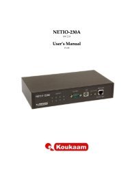
The following example illustrates the driver installation on Windows XP:<br />
After connecting to the USB port the hardware installation assistant starts:<br />
Here you select: "No, not at this time" and click next.<br />
The following window appears:<br />
Please select "Install from a list or specific location” and click "next".<br />
11/33<br />
Hasenbrink 4, 32052 Herford, Germany Tel. +49 (0) 5221 929660 Fax +49 (0) 5221 9296628
<strong>antrax</strong> Datentechnik GmbH<br />
info@<strong>antrax</strong>.<strong>de</strong> - www.<strong>antrax</strong>.<strong>de</strong><br />
The following window appears:<br />
Select the item "browse" and specify the directory on the local hard disk, into which you<br />
extracted the ZIP file containing the driver files.<br />
Click "next".<br />
The following window appears:<br />
Select "continue installation".<br />
12/33<br />
Hasenbrink 4, 32052 Herford, Germany Tel. +49 (0) 5221 929660 Fax +49 (0) 5221 9296628
<strong>antrax</strong> Datentechnik GmbH<br />
info@<strong>antrax</strong>.<strong>de</strong> - www.<strong>antrax</strong>.<strong>de</strong><br />
The following window appears:<br />
Once all necessary files are copied , click "continue”<br />
The following window appears:<br />
Select "Finish".<br />
13/33<br />
Hasenbrink 4, 32052 Herford, Germany Tel. +49 (0) 5221 929660 Fax +49 (0) 5221 9296628
<strong>antrax</strong> Datentechnik GmbH<br />
info@<strong>antrax</strong>.<strong>de</strong> - www.<strong>antrax</strong>.<strong>de</strong><br />
Software<br />
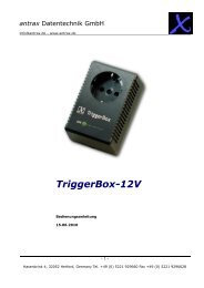
The software for controlling the <strong>MultiBox</strong> via a virtual COM port is now configured. To check<br />
whether the new COM port is working correctly, please have a look at the control panel in the<br />
<strong>de</strong>vice manager:<br />
If a sub item "<strong>antrax</strong> UniBox" is listed here at "ports" (COM & LPT), the installation was<br />
successful.<br />
The <strong>MultiBox</strong> is now ready.<br />
The <strong>MultiBox</strong> can now be operated with the service software "ASS" (= Antrax-Service-Software)<br />
or other software (such as HyperTerminal, Telix or any other terminal program).<br />
The control by the monitored main program is realised by its output to the serial interface.<br />
The service program "ASS" (= Antrax-Service-Software) can be downloa<strong>de</strong>d free of charge at:<br />
http://www.<strong>antrax</strong>.<strong>de</strong><br />
14/33<br />
Hasenbrink 4, 32052 Herford, Germany Tel. +49 (0) 5221 929660 Fax +49 (0) 5221 9296628
<strong>antrax</strong> Datentechnik GmbH<br />
info@<strong>antrax</strong>.<strong>de</strong> - www.<strong>antrax</strong>.<strong>de</strong><br />
Function Reference<br />
Mo<strong>de</strong>s<br />
Syntax Description<br />
{1} Modus =<br />
1<br />
{n} Modus =<br />
2<br />
{1} Modus =<br />
3<br />
{1} Modus =<br />
4<br />
{n} Modus =<br />
5<br />
{+} Modus =<br />
6<br />
Output 1 as WatchBox (switches the own connected computer). The active<br />
main function in this mo<strong>de</strong> is the controlled ON/OFF switching of the<br />
computer:<br />
- after Power ON (and box without function) → Outlet ON!<br />
- onapon = 1, triapon = 0<br />
Output as SwitchBox (switches any other consumer). The active main<br />
function in this mo<strong>de</strong> is the ON switching of consumers:<br />
- the Watchdog functions are <strong>de</strong>activated<br />
- after Power ON (and box without function) → Outlet OFF!<br />
- Default setting<br />
- onapon = 0, triapon = 0<br />
- n = 1…5<br />
Output 1 as WatchBox in fail save mo<strong>de</strong> (switches the own connected<br />
computer). The active main function in this mo<strong>de</strong> is the controlled ON/OFF<br />
switching of the computer:<br />
- after Power ON (and box without function) → Outlet ON!<br />
- The set time Tf already expires starting with Power ON and switches<br />
the <strong>MultiBox</strong> ON/OFF, if not triggered within the time Tf<br />
- onapon = 1, triapon = 1<br />
Output1 as WatchBox in neutral-power-ON mo<strong>de</strong> (switches any other<br />
consumer). Like mo<strong>de</strong> 1 but the <strong>MultiBox</strong> remains switched OFF after<br />
Power ON<br />
- onapon = 0, triapon = 0<br />
Operate output n as slave. The switching state of output n follows the state<br />
of output 1. Whereby the switching ON of output n can also be timely<br />
<strong>de</strong>layed. If by {n}tv=x a time x (specified in seconds) is set, the output is<br />
switched ON only after time x.<br />
- n=2…5<br />
Activate programmable sequence control<br />
All programmable sequence control concerning commands are only accepted<br />
if mo<strong>de</strong> 6 is set. In this mo<strong>de</strong> the Watchdog and master-slave functionality<br />
is <strong>de</strong>activated.<br />
In this mo<strong>de</strong> the PLC can be started, stopped and programmed. The mo<strong>de</strong> is<br />
quit, when for any channel the mo<strong>de</strong> 2 (SwitchBox) is being set.<br />
15/33<br />
Hasenbrink 4, 32052 Herford, Germany Tel. +49 (0) 5221 929660 Fax +49 (0) 5221 9296628
<strong>antrax</strong> Datentechnik GmbH<br />
info@<strong>antrax</strong>.<strong>de</strong> - www.<strong>antrax</strong>.<strong>de</strong><br />
Syntax Description<br />
{n} onapon<br />
= 1<br />
{n} triapon<br />
= 1<br />
{n} PLCapon<br />
= 1<br />
ONAfterPowerON<br />
Describes the switching behaviour of the specified channel after Power ON of<br />
the <strong>MultiBox</strong>.<br />
If with {n} mo<strong>de</strong> = x a mo<strong>de</strong> is set, onapon will automatically set to the<br />
correct value. It can however be changed later (e.g. that the <strong>MultiBox</strong><br />
operates in mo<strong>de</strong> 2 [SwitchBox] and is switched ON after a Power-ON<br />
[{+}onapon=1]). Following values are possible:<br />
0 Outlet remains OFF after Power-ON (e.g. in mo<strong>de</strong> 2)<br />
1 Outlet is switched ON after Power-ON (e.g. in mo<strong>de</strong> 1)<br />
2 Outlet is switched ON, if the outlet was switched ON before failure of<br />
current<br />
- Range: 0 … 2<br />
- Default setting: 0<br />
- with {+}mo<strong>de</strong> = n may be set again<br />
- n=1…5<br />
TRIgAfterPowerON<br />
Describes the behaviour of the specified channel after Power-ON of the<br />
<strong>MultiBox</strong>.<br />
If with {n}Modus = x a mo<strong>de</strong> is set, triapon automatically is set to the<br />
correct value. It can however be changed later. Following values are<br />
possible:<br />
0 <strong>MultiBox</strong> must not be trggered after Power-ON and switching ON of<br />
the outlet (e.g. in mo<strong>de</strong> 1)<br />
1 <strong>MultiBox</strong> must be triggered after Power-ON and switching ON of the<br />
outlet (e.g. in mo<strong>de</strong> 3)<br />
- Range: 0 … 1<br />
- Default setting: 0<br />
- with {+}mo<strong>de</strong> = n may be set again<br />
PLCAfterPowerON<br />
Describes the behaviour of the programmable sequence control (=PLC) after<br />
Power-ON of the <strong>MultiBox</strong>. This pre-setting is only consi<strong>de</strong>red, if before<br />
Power-OFF mo<strong>de</strong> 6 is set.<br />
Following values are possible:<br />
0 The <strong>MultiBox</strong> after Power-ON waits for the start signal of the<br />
switching sequence<br />
1 The <strong>MultiBox</strong> after Power-ON immediately starts the switching<br />
sequence<br />
- Range: 0 … 1<br />
- Default setting: 0<br />
16/33<br />
Hasenbrink 4, 32052 Herford, Germany Tel. +49 (0) 5221 929660 Fax +49 (0) 5221 9296628
<strong>antrax</strong> Datentechnik GmbH<br />
info@<strong>antrax</strong>.<strong>de</strong> - www.<strong>antrax</strong>.<strong>de</strong><br />
Triggering<br />
Syntax Description<br />
{1} Tr = 20 Can only be executed in mo<strong>de</strong> 1, 3 or 4(<strong>MultiBox</strong>).<br />
Setting the re-trigger time in seconds<br />
- within this time frame triggering is to be executed regularly,<br />
otherwise a Watchdog event is being released<br />
- Range: 1 … 214748364<br />
- Default setting: 60 s<br />
{1} Ta = 10 Can only be executed in mo<strong>de</strong> 1, 3 or 4 (<strong>MultiBox</strong>).<br />
Setting the turn-off time in seconds<br />
- upon occurrence of the Watchdog event the socket is switched OFF<br />
for the set time<br />
- Range: 1 … 214748364<br />
- Default setting: 10 s<br />
{1} Tf = 500 Can only be executed in mo<strong>de</strong> 1, 3 or 4 (<strong>MultiBox</strong>).<br />
Setting the error time in seconds<br />
Time up to next Watchdog event, if after a Watchdog event, processed by<br />
the <strong>MultiBox</strong> or by general Power-ON, no [anew] triggering is executed (e.g.<br />
'Windows hangs-up while booting')<br />
- Range: 0 … 214748364<br />
- Default setting: 900 s<br />
{1} Trig<br />
{1} Trig = 10<br />
At a value of 0 the boot-error function is <strong>de</strong>activated, i. e. after a Watchdog<br />
event the outlet is being switched ON permanently (also see → {+} maxrst)<br />
Can only be executed in mo<strong>de</strong> 1, 3 or 4 (<strong>MultiBox</strong>).<br />
Release triggering<br />
- with the first triggering the <strong>MultiBox</strong> is armed and must be triggered<br />
on regular basis thereon<br />
- LED flashes (duty cycle 50:50, 0.5Hz)<br />
- if the {+}Trig command is sent, the <strong>MultiBox</strong> immediately switches<br />
ON the consumer and waits for the next triggering (re-trigger time is<br />
running)<br />
Can only be executed in mo<strong>de</strong> 1, 3 or 4 (<strong>MultiBox</strong>).<br />
Trigger release with <strong>de</strong>livery of a status value:<br />
Function as above with the exception that that only one trigger is released, if<br />
the status value is differs from the one before. The last passed status value<br />
is placed in non-volatile memory upon occurrence of a Watchdog event. The<br />
saved and the last sent status value can be queried with the command "{+}<br />
Get". With the command "{+} Del Status" the saved and the last sent state<br />
can be <strong>de</strong>leted. The state values are only displayed if a status has in fact<br />
been reported. After <strong>de</strong>leting the values with "{+} Del Status" the lines<br />
TRIG-STATE and ERROR-STATE are not issued.<br />
17/33<br />
Hasenbrink 4, 32052 Herford, Germany Tel. +49 (0) 5221 929660 Fax +49 (0) 5221 9296628
<strong>antrax</strong> Datentechnik GmbH<br />
info@<strong>antrax</strong>.<strong>de</strong> - www.<strong>antrax</strong>.<strong>de</strong><br />
Syntax Description<br />
{1} maxrst =<br />
3<br />
Can only be executed in mo<strong>de</strong> 1, 3 or 4 (<strong>MultiBox</strong>).<br />
Limit the number of restarts of the PC<br />
This command is only effective if the command "Tf" is bigger than 0:<br />
In or<strong>de</strong>r to avoid, that a PC after a reset and missing triggering is being<br />
restarted over and over, use {+} maxrst = n to set a maximum amount of<br />
restarts. The internal counter ACT-RST is being updated by 1 with every new<br />
restart. When the counter ACT-RST reaches the set value of the parameter<br />
"maxrst", the outlet remains permanently <strong>de</strong>activated.<br />
- Range: 0 … 65535<br />
- if 0 → no limitation<br />
- Default setting: 10<br />
18/33<br />
Hasenbrink 4, 32052 Herford, Germany Tel. +49 (0) 5221 929660 Fax +49 (0) 5221 9296628
<strong>antrax</strong> Datentechnik GmbH<br />
info@<strong>antrax</strong>.<strong>de</strong> - www.<strong>antrax</strong>.<strong>de</strong><br />
Switching Operations + Sequences<br />
Syntax Description<br />
{n} Tv = 12 Can be executed in any mo<strong>de</strong>.<br />
Turn-on <strong>de</strong>lay in seconds afterPower-ON<br />
This time is after a Power-ON of the <strong>MultiBox</strong> all following processes/timers<br />
up-streamed and allows the <strong>de</strong>layed switching ON of the outlet (e.g. for<br />
synchronisation of "fast" <strong>de</strong>vices)<br />
- Range: 0 … 214748364<br />
- Default setting: 0<br />
- n=1…5<br />
{n} Off Switch OFF one or all outputs immediately. If a value from 1…5 is set, the<br />
corresponding output is switched OFF, by setting of "+" all outputs are<br />
switched OFF<br />
- n=1…5 / "+"<br />
{n} On Switch ON one or all outputs immediately. If a value from 1…5 is set, the<br />
corresponding output is switched ON, by setting of "+" all outputs are<br />
switched ON<br />
{n} Off =<br />
100<br />
{n} Off =<br />
1000<br />
{2} On = 20<br />
{2} Off = 40<br />
{3} Off = 20<br />
{3} On = 40<br />
- n=1…5 / "+"<br />
Direct switch OFF after the set time in seconds<br />
- Range: 0 … 214748364<br />
- if after {n} On = m – command is set, a ON/OFF sequence is started<br />
- n=1…5<br />
Direct switch ON after the set time in seconds<br />
- Range: 0 … 214748364<br />
- if after {n} Off = m – command is set, a OFF/ON sequence is stated<br />
- n=1…5<br />
A ON/OFF sequence starts.<br />
Output 2 of the <strong>MultiBox</strong> is switched ON after 20 seconds. After switch ON,<br />
40 seconds later switch OFF is executed.<br />
A OFF/ON sequence starts..<br />
Output 3 of the <strong>MultiBox</strong> is switched OFF after 20 seconds. After switch<br />
OFF, 40 seconds later switch ON is executed.<br />
Requirements for operating with sequences:<br />
- commands must be set directly consecutively<br />
- the second command must be set before the set time in the first<br />
command expires<br />
- a sequence is interrupted by any command, that causes switching of<br />
the outlet (directly or on time basis).<br />
- a sequence is being interrupted by the command{n} Deaktiv and {1}<br />
Trig<br />
Caution: The given times are ad<strong>de</strong>d ad<strong>de</strong>d up!<br />
19/33<br />
Hasenbrink 4, 32052 Herford, Germany Tel. +49 (0) 5221 929660 Fax +49 (0) 5221 9296628
<strong>antrax</strong> Datentechnik GmbH<br />
info@<strong>antrax</strong>.<strong>de</strong> - www.<strong>antrax</strong>.<strong>de</strong><br />
Programmable Sequence Control(= PLC)<br />
Mo<strong>de</strong> 6 is required for all following commands:<br />
Syntax Description<br />
{+} PLCstart Start sequence or time out<br />
{+} PLCstop Stop sequence, switch OFF all channels (mo<strong>de</strong> 6 is required)<br />
{+} PLCget Read out current switching sequence<br />
Format: serial number, time in seconds, channel, state<br />
Example:<br />
PLCAPON=0<br />
PLC:<br />
01,Time=000000,Ch1,ON<br />
02,Time=000000,Ch2,OFF<br />
03,Time=000000,Ch3,OFF<br />
04,Time=000000,Ch4,OFF<br />
..<br />
..<br />
15,Time=000022,Ch2,OFF<br />
16,Time=000024,Loop<br />
OK<br />
{+} PLCset= Insert a switching step in the current switching sequence<br />
Format: serial number, time in seconds, channel, state<br />
{+}<br />
PLCclear=1<br />
{+} PLCclear<br />
all<br />
Example<br />
{+}PLCset=400,3,OFF<br />
This command <strong>de</strong>activates channel 3 after 400 seconds. All steps are<br />
automatically sorted, according to their time stamp, in the current<br />
switching sequence. Possible states: ON, OFF, LOOP and END.<br />
Remove the specified or all switching steps from the current switching<br />
sequence<br />
{+} PLCstore Transmit and store the current switching sequence to the configuration<br />
memory permanently (a non saved switching sequence is lost after a<br />
Power-OFF/Power-ON)<br />
Loading and saving function of a switching sequence with the service program "ASS" (= Antrax-Service-<br />
Software) into a text file (*.PLC) exclusively uses the <strong>MultiBox</strong> commands {+}PLCget and<br />
{+}PLCset. For this function the <strong>MultiBox</strong> does not offer further special functionality, since with the<br />
"back load" of a switching sequence into the <strong>MultiBox</strong> basically, the gradually read-out text with<br />
{+}PLCget with {+}PLCset is loa<strong>de</strong>d back to the <strong>MultiBox</strong> again.<br />
20/33<br />
Hasenbrink 4, 32052 Herford, Germany Tel. +49 (0) 5221 929660 Fax +49 (0) 5221 9296628
<strong>antrax</strong> Datentechnik GmbH<br />
info@<strong>antrax</strong>.<strong>de</strong> - www.<strong>antrax</strong>.<strong>de</strong><br />
Miscellaneous<br />
Syntax Description<br />
{+} Echo ON Switch ON interface echo<br />
- Default setting: ON<br />
{+} Echo<br />
OFF<br />
"Testseite"<br />
{+}<br />
Testseite<br />
Switch OFF interface echo<br />
- Default setting: OFF<br />
If this string is recognised, the LED flashes 3 times<br />
(Help for the operator, if the <strong>MultiBox</strong> is set up as COM printer)<br />
{n} Deaktiv Can only be executed in mo<strong>de</strong> 1, 3 or 4 (<strong>MultiBox</strong>).<br />
Deactive <strong>MultiBox</strong><br />
- no triggering required<br />
- all times remain set<br />
- <strong>de</strong>pending on momentary state: LED static ON or OFF<br />
- n=0…5<br />
{+} Del<br />
EEPROM<br />
{+} Del<br />
Status<br />
Can only be executed in mo<strong>de</strong> 1, 3 or 4 (<strong>MultiBox</strong>).<br />
Delete non-volatile configuration memory and set <strong>de</strong>fault values.<br />
Can only be executed in mo<strong>de</strong> 1, 3 or 4 (<strong>MultiBox</strong>).<br />
Deletes the stored and the last status, that with the {+} Trig = n command<br />
has been passed.<br />
Deletes the counter for the WatchDog events<br />
21/33<br />
Hasenbrink 4, 32052 Herford, Germany Tel. +49 (0) 5221 929660 Fax +49 (0) 5221 9296628
<strong>antrax</strong> Datentechnik GmbH<br />
info@<strong>antrax</strong>.<strong>de</strong> - www.<strong>antrax</strong>.<strong>de</strong><br />
General Command Processing<br />
- <strong>MultiBox</strong> commands are always initiated with {n}. Whereby n stands for the number of the<br />
outlet or for "+" when all outputs are to be addressed.<br />
- Spaces are ignored.<br />
- Upper and lower case letters are not distinguished.<br />
- Each command must at least be <strong>de</strong>termined with CR (character 13).<br />
- All <strong>MultiBox</strong> times remain set, until they are explicitly set anew.<br />
- All settings are kept in a non-volatile memory and "survive" even a power outage.<br />
- Important for manual input via a terminal program: The time-out during a manual command<br />
input is 5 seconds (that means: type quickly..!).<br />
- At Echo = On the command execution with CRLF + 'OK' + CRLF will be acknowledged.<br />
- Unrecognised commands are acknowledged with CRLF + '?' + CRLF.<br />
- Before sending a command, the previous command must have been recognised by the<br />
<strong>MultiBox</strong> (receipt or time <strong>de</strong>lay).<br />
If an output of the <strong>MultiBox</strong> is set to one of the 5 mo<strong>de</strong>s with {n}, the parameters "onapon"<br />
and "triapon" are automatically changed. If then additional a combination is set with {n}onapon<br />
= m or {1}triapon = m, that does not fit to one of the 4 mo<strong>de</strong>s (see chapter "mo<strong>de</strong>s", page 15)<br />
the mo<strong>de</strong> "USERDEFINED" is displayed after the command {+}Get.<br />
22/33<br />
Hasenbrink 4, 32052 Herford, Germany Tel. +49 (0) 5221 929660 Fax +49 (0) 5221 9296628
<strong>antrax</strong> Datentechnik GmbH<br />
info@<strong>antrax</strong>.<strong>de</strong> - www.<strong>antrax</strong>.<strong>de</strong><br />
Read States<br />
Syntax Description<br />
{n} Remain Check of the remaining time until next switching operation<br />
Display: COUNT=214748364...0 (line 4 of the status inquiry)<br />
{n} Get Send all values and states<br />
(Description of the states see below)<br />
{+} F Query current software version (= date of release)<br />
{+} H Query hardware ID<br />
State query with "{+} Get":<br />
<strong>MultiBox</strong> Switchbox<br />
<strong>MultiBox</strong>=<br />
<strong>MultiBox</strong>_FS=<br />
<strong>MultiBox</strong>_NP=<br />
00...15 CRLF SWITCHBOX= 00...14 CRLF<br />
RELAIS= 0...1 CRLF RELAIS= 0...1 CRLF<br />
TIME= 0...2147483 CRLF TIME= 0...2147483 CRLF<br />
64<br />
64<br />
COUNT= 214748364. CRLF COUNT= 214748364. CRLF<br />
..0<br />
..0<br />
TR= 1...2147483<br />
64<br />
CRLF ONAPON= 0...2 CRLF<br />
TA= 1...2147483 CRLF TV= 0...2147483 CRLF<br />
64<br />
64<br />
TF= 0...2147483<br />
64<br />
CRLF OK CRLF<br />
TV= 0...2147483<br />
64<br />
CRLF<br />
TRIG-STATE= 0...2147483<br />
64<br />
CRLF *)<br />
ERROR-STATE= 0...2147483 CRLF *)<br />
64<br />
ONAPON= 0...2 CRLF<br />
TRIAPON= 0...1 CRLF<br />
RST-COUNTER= 0...65535 CRLF<br />
MAX-RST= 0...65535 CRLF **)<br />
ACT-RST= 0...65535 CRLF **)<br />
OK CRLF<br />
*) These lines are only issued when a status value is present.<br />
**) These lines are only issued if MAX-RST > 0.<br />
23/33<br />
Hasenbrink 4, 32052 Herford, Germany Tel. +49 (0) 5221 929660 Fax +49 (0) 5221 9296628
<strong>antrax</strong> Datentechnik GmbH<br />
info@<strong>antrax</strong>.<strong>de</strong> - www.<strong>antrax</strong>.<strong>de</strong><br />
Return values in <strong>de</strong>tail:<br />
Return Description<br />
<strong>MultiBox</strong>=00...05<br />
<strong>MultiBox</strong>_FS=00...05<br />
<strong>MultiBox</strong>_NP=00...05<br />
SWITCHBOX=00,01,03,04<br />
USERDEFINED=00...05<br />
In addition, <strong>de</strong>pending on<br />
the event, the opposite<br />
values add together:<br />
e. g:<br />
RELAIS=0...1 0 = Outlet is OFF<br />
1 = Outlet is ON<br />
00 = WB / SB is switched OFF<br />
01 = WB / SB is switched ON<br />
02 = WB waiting for next triggering<br />
03 = WB / SB waits for switch OFF<br />
04 = WB / SB waits for switch ON<br />
05 = WB reboot time running out<br />
+ 10 ON/OFF switching sequence follows<br />
14 = Sequence started + waiting for switch ON<br />
TIME=0...214748364 Time in seconds after Power ON<br />
COUNT=214748364...0 Time in seconds to trigger the next operation,<br />
e.g. after "{+} On=20"<br />
yields<br />
"{+} Get" → COUNT=20...0 <strong>de</strong>crementing, at counter 0<br />
the outlet is switched ON<br />
TR=1...214748364 Stored re-trigger time<br />
TA=1...214748364 Stored switch OFF time<br />
TF=0...214748364 Stored error time<br />
TRIG-STATE=0...214748364 Last state set with "{+} Trig" = n<br />
ERROR-<br />
STATE=0...214748364<br />
Last stored last state set with "{+} Trig" = n before a<br />
Watchdog event<br />
RST-COUNTER=0...65535 Number of initiated resets of the <strong>MultiBox</strong> since last reset<br />
with {+} Del Status<br />
MAX-RST=0...65535 Maximum number of initiated resets of the <strong>MultiBox</strong> (then<br />
channel 1 is permanently switched OFF)<br />
ACT-RST =0...65535 Number of initiated resets of the <strong>MultiBox</strong> since last<br />
triggering<br />
24/33<br />
Hasenbrink 4, 32052 Herford, Germany Tel. +49 (0) 5221 929660 Fax +49 (0) 5221 9296628
<strong>antrax</strong> Datentechnik GmbH<br />
info@<strong>antrax</strong>.<strong>de</strong> - www.<strong>antrax</strong>.<strong>de</strong><br />
Please note:<br />
TRIG-STATE and ERROR-STATE are only issued when a status value is present.<br />
After <strong>de</strong>leting the status with "{+} Del Status" these lines will not be displayed until a new status<br />
is given with "{+} Trig = 0...214748364".<br />
25/33<br />
Hasenbrink 4, 32052 Herford, Germany Tel. +49 (0) 5221 929660 Fax +49 (0) 5221 9296628
<strong>antrax</strong> Datentechnik GmbH<br />
info@<strong>antrax</strong>.<strong>de</strong> - www.<strong>antrax</strong>.<strong>de</strong><br />
Watchdog Programming<br />
General<br />
Basically, there is two different types of control of the <strong>MultiBox</strong>. No doubt, the best and safest method<br />
of control is realised by the main program itself, however that means the the source co<strong>de</strong> of the main<br />
program is present and can/is allowed/should be modified. The section "1. Method: control by the<br />
monitored software” refers to the corresponding changes in the source co<strong>de</strong>. If the source co<strong>de</strong> of the<br />
main program is not available the <strong>MultiBox</strong> must be operated using a background program (2.<br />
Method). Unfortunately this is only the second best method of control as it could cause bugs this<br />
process in principal can not recognise. This is, by the way, a problem that all Watchdogs have to face.<br />
By far the most common programming errors (program in an endless loop with watchdog triggering),<br />
however, can be reliably <strong>de</strong>tected by the <strong>MultiBox</strong> ... !<br />
Addressing the <strong>MultiBox</strong><br />
Settings and triggering of the <strong>MultiBox</strong> can only be ma<strong>de</strong> via the serial of the USB interface.<br />
In the simplest case, it is sufficient after setting the required Watchdog mo<strong>de</strong> in the main program, to<br />
only output the the cyclic triggering. In this case the <strong>de</strong>fault switching times for re-trigger and switching<br />
time are used. Initialisation of the <strong>MultiBox</strong> is not required.<br />
The <strong>MultiBox</strong> switching times can vary in wi<strong>de</strong> limits, so that the computer for example remains<br />
switched OFF longer (switch OFF time TA) or is operated with very long re-trigger times (TR). All<br />
switching times can be set anew any time.<br />
Furthermore the <strong>MultiBox</strong> recognises the problem "computer (or Windows) not booting": After an error<br />
re-start the triggering by the <strong>MultiBox</strong> must be executed by a time pre-set (TF) … if not, the <strong>MultiBox</strong><br />
causes another error re-start, and so on.<br />
The <strong>MultiBox</strong> can also be operated as simple switch box without Watchdog functionality. In this case,<br />
with the commands "{+} On" and "{+} Off" external <strong>de</strong>vices, like mo<strong>de</strong>ms, printers, lamps or<br />
measuring <strong>de</strong>vices (also time controlled) can be switched ON/OFF directly by the computer.<br />
Program Error Detection<br />
With conventional Watchdogs a re-triggering is already realised through the writing process (or function<br />
call itself), namely it can not be <strong>de</strong>tected, whether any changes happened in the main program after<br />
two consecutive triggering sequences. This leads to, an infinite loop in the main program, containing a<br />
triggering of the Watchdog, is not recognised.<br />
The <strong>MultiBox</strong> has a different approach and also evaluates, by event of triggering (optional) the passed<br />
states variables. With to consecutive triggering events with the same content the activated <strong>MultiBox</strong><br />
ignores the last triggering or <strong>de</strong>fines it as not taken place. Only with this behaviour the above <strong>de</strong>scribed<br />
error can safely be recognised.<br />
26/33<br />
Hasenbrink 4, 32052 Herford, Germany Tel. +49 (0) 5221 929660 Fax +49 (0) 5221 9296628
<strong>antrax</strong> Datentechnik GmbH<br />
info@<strong>antrax</strong>.<strong>de</strong> - www.<strong>antrax</strong>.<strong>de</strong><br />
Examples<br />
Example 1<br />
In this example the <strong>MultiBox</strong>, with the computer connected to channel 1, executes a controlled shut<br />
down and switch OFF, and then switches ON the computer 24 hours later..<br />
Settings:<br />
1. Waiting period of 60 seconds for the controlled shut down of the PC is set.<br />
2. Switch OFF time of 86400 seconds (= 24 hours) is set.<br />
3. Thereafter, the program can be stopped and the PC is shut down.<br />
...<br />
...<br />
Send('{1} off = 60');<br />
Send('{1} on = 86400');<br />
...<br />
...<br />
...<br />
...<br />
End program and shut down PC ...<br />
Example 2<br />
In this (Delphi-) example a <strong>MultiBox</strong> triggering (with infinite loop <strong>de</strong>tection) at channel 1 is executed<br />
by the main program. In this case we assume that the procedure "Send" sends the specified string to<br />
the serial interface.<br />
Setting:<br />
1. Re-trigger time of 30 seconds is set.<br />
2. Switch OFF time of 20 seconds is set..<br />
3. Error time of 180 seconds is set.<br />
4. Thereafter regularly triggering.<br />
var nStatus : integer;<br />
cStatus : string;<br />
Send('{1} tr = 30');<br />
Send('{1} ta = 20');<br />
Send('{1} tf = 180');<br />
Send('{1} Modus = 1');<br />
nStatus := 0;<br />
// Main loop of the program<br />
repeat<br />
nStatus := nStatus + 1; // Increment status variable<br />
cString := IntToStr(nStatus); // Status variable in String<br />
Send('{1} trig = ' + cString); // trigger <strong>MultiBox</strong><br />
...<br />
...<br />
...<br />
until ...<br />
27/33<br />
Hasenbrink 4, 32052 Herford, Germany Tel. +49 (0) 5221 929660 Fax +49 (0) 5221 9296628
<strong>antrax</strong> Datentechnik GmbH<br />
info@<strong>antrax</strong>.<strong>de</strong> - www.<strong>antrax</strong>.<strong>de</strong><br />
Programmable Sequence Control<br />
General<br />
The <strong>MultiBox</strong> has an integrated sequence control. This, like a simple PLC sequence control allows<br />
automatic or time <strong>de</strong>pen<strong>de</strong>nt switching operations and thus a a permanent connected and running<br />
control computer is obsolete.<br />
The programmable sequence control is activated by the <strong>MultiBox</strong> being switched to mo<strong>de</strong> 6. Only in<br />
this mo<strong>de</strong> the switching sequence can be programmed and started. The switching step programming is<br />
always done with the help of commands (all with prefix "PLC") via the serial or USB interface. The actual<br />
operation, namely starting, stopping and pausing the switching sequence can also be realised through<br />
the interface, but also directly on the integrated control panel.<br />
Addressing via the interface<br />
Basic Process:<br />
1.) Set <strong>MultiBox</strong> to mo<strong>de</strong> 6 with "{+} modus=6"<br />
2.) with "{+}PLCget" check the current control sequence and if necessary with "{+}PLCclear",<br />
"{+}PLCset" and "{+}PLCstore" modify and safe to the configuration memory permanently<br />
3.) start the control sequence with "{+}PLCstart"<br />
4.) the control sequence can be paused by anew "{+}PLCstart" ("pause function" like CD player)<br />
5.) the termination of the switching sequence is done with "{+}PLCstop" (all channels are switched<br />
OFF)<br />
6.) the return from mo<strong>de</strong> 6 into a different mo<strong>de</strong> is possible when mo<strong>de</strong> 2 is set for any channel<br />
Addressing via the touch panel<br />
Basic Process:<br />
1.) by pressing at least 3 seconds on both push buttons on the control panel the <strong>MultiBox</strong> is set to<br />
mo<strong>de</strong> 6<br />
2.) by pressing "SELECT" the current control sequence is started or set to pause<br />
3.) by pressing "SET" the control sequence is interrupted(all channels are switched OFF)<br />
4.) by newly pressing at least 3 seconds the two push button on the control panel all channels of the<br />
<strong>MultiBox</strong> are set to mo<strong>de</strong> 2<br />
If the <strong>MultiBox</strong> is set to mo<strong>de</strong> 6 and the control sequence has not been started yet, the 5 LEDs show a<br />
flash in running light. This running light is also (briefly) displayed, when an endurance run sequence<br />
after a loop command restarts "at zero"<br />
28/33<br />
Hasenbrink 4, 32052 Herford, Germany Tel. +49 (0) 5221 929660 Fax +49 (0) 5221 9296628
<strong>antrax</strong> Datentechnik GmbH<br />
info@<strong>antrax</strong>.<strong>de</strong> - www.<strong>antrax</strong>.<strong>de</strong><br />
Operation<br />
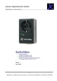
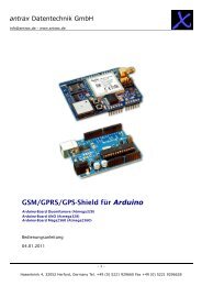
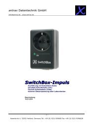
Integrated control panel<br />
LED for channel 1 (red)<br />
Button "SELECT"<br />
Button "SET"<br />
USB interface<br />
or<br />
serial interface<br />
19" fastening angle<br />
LED for channels 2 … 5 (green)<br />
29/33<br />
Hasenbrink 4, 32052 Herford, Germany Tel. +49 (0) 5221 929660 Fax +49 (0) 5221 9296628
<strong>antrax</strong> Datentechnik GmbH<br />
info@<strong>antrax</strong>.<strong>de</strong> - www.<strong>antrax</strong>.<strong>de</strong><br />
Operating<br />
LED for channel 1 (red)<br />
Permanently OFF <strong>MultiBox</strong> not in Watchdog mo<strong>de</strong>, outlet OFF<br />
Permanently ON <strong>MultiBox</strong> not in Watchdog mo<strong>de</strong>, outlet ON<br />
Flashing (duty cycle 50:50,<br />
0.5Hz)<br />
Flashing (duty cycle 50:50,<br />
5Hz)<br />
Flash (duty cycle 10:90,<br />
0.5Hz)<br />
<strong>MultiBox</strong> in Watchdog mo<strong>de</strong><br />
(Tr expires, waiting for next trigger)<br />
<strong>MultiBox</strong> in Watchdog mo<strong>de</strong><br />
(Ta expires, waiting for switch ON after a Watchdog<br />
event)<br />
<strong>MultiBox</strong> in Watchdog mo<strong>de</strong><br />
(Tf expires, waiting for anew trigger after anew switch<br />
ON)<br />
Flashes 3 times briefly A text page was recognised (while setting a COM printer)<br />
LED 2 x briefly light with 1Hz<br />
repetition<br />
LED 2 x briefly dark with 1Hz<br />
repetition<br />
LED for channels 2…5 (green)<br />
<strong>MultiBox</strong> not in Watchdog mo<strong>de</strong>, outlet will be switched<br />
ON after course of time started<br />
<strong>MultiBox</strong> not in Watchdog mo<strong>de</strong>,, outlet is switched OFF<br />
after course of time started<br />
Permanently OFF Output of the <strong>MultiBox</strong> is permanently OFF<br />
Permanently ON Output of the <strong>MultiBox</strong> is permanently ON<br />
Flash (duty cycle 10:90,<br />
0.5Hz)<br />
The output of the <strong>MultiBox</strong> either waits for time<br />
scheduled switch ON or it is set as slave and waits for<br />
switch ON of the master<br />
All LEDs in running light: Mo<strong>de</strong> 6 activated and control sequence not yet started.<br />
30/33<br />
Hasenbrink 4, 32052 Herford, Germany Tel. +49 (0) 5221 929660 Fax +49 (0) 5221 9296628
<strong>antrax</strong> Datentechnik GmbH<br />
info@<strong>antrax</strong>.<strong>de</strong> - www.<strong>antrax</strong>.<strong>de</strong><br />
Buttons<br />
Mo<strong>de</strong> 1 … 5:<br />
By pressing the SELECT button the LED for channel 1 starts flashing. Re-pressing the SELECT<br />
button causes switching further. When pressing the SET button for more than 3 seconds the<br />
selected channel is switched to the each other mo<strong>de</strong> (= toggled). Manual switching always<br />
causes <strong>de</strong>activation of any time or master <strong>de</strong>pen<strong>de</strong>nt operation for the appropriate channel.<br />
After pressing the SET button, the LED of the previously selected channel displays the switching<br />
state of the outlet.<br />
Mo<strong>de</strong> 6:<br />
By pressing the SELECT button the current control sequence is started or an ongoing control<br />
sequence is interrupted (pause function).<br />
By pressing the SET button an ongoing control sequence is interrupted and and all channels are<br />
switched OFF, the LEDs display a running light.<br />
Serial Interface/ USB Interface<br />
- Connect via COM interface or USB (= virtual COM interface), 9600-N-8-1<br />
- No hard- or software handshake (3-wire connection, RxD-TxD-GND)<br />
31/33<br />
Hasenbrink 4, 32052 Herford, Germany Tel. +49 (0) 5221 929660 Fax +49 (0) 5221 9296628
<strong>antrax</strong> Datentechnik GmbH<br />
info@<strong>antrax</strong>.<strong>de</strong> - www.<strong>antrax</strong>.<strong>de</strong><br />
Difference between mo<strong>de</strong> 1 (<strong>MultiBox</strong>) and mo<strong>de</strong> 3 (<strong>MultiBox</strong>_FS)<br />
- In mo<strong>de</strong> 1 the <strong>MultiBox</strong> is started after a Power ON, without waiting for triggering, i. e. the<br />
connected PC at channel 1 is permanently switched ON. After that, it is in the responsibility of<br />
the PC to address the <strong>MultiBox</strong>.<br />
- In mo<strong>de</strong> 3 the m Modus 3 the <strong>MultiBox</strong> is started and immediately waits for triggering. If the<br />
connected PC is does not report back within the set time Tf, the <strong>MultiBox</strong> executes a reset and<br />
is then in the reset loop, i. e. reset is being continued until the PC reports back.<br />
Difference between mo<strong>de</strong> 1 (<strong>MultiBox</strong>) and mo<strong>de</strong> 4 (<strong>MultiBox</strong>_NP)<br />
- In mo<strong>de</strong> 1 the <strong>MultiBox</strong> is started after a Power ON, without waiting for triggering, i. e. the<br />
connected PC is permanently switched ON. After that, it is in the responsibility of the PC to<br />
address the <strong>MultiBox</strong>.<br />
- In mo<strong>de</strong> 4 the <strong>MultiBox</strong> behaves as in mo<strong>de</strong> 1 with the difference, that channel 1 remains<br />
switched OFF after Power ON.<br />
Difference between mo<strong>de</strong> 1...5 and mo<strong>de</strong> 6 (process control)<br />
- If the <strong>MultiBox</strong> is set to mo<strong>de</strong> 6 whilst Power OFF, the <strong>MultiBox</strong> "looks" for Power ON on<br />
parameter "PLCapon". Depending on the pre-set mo<strong>de</strong> the current control sequence is not<br />
started ((PLCapon = 0) or started (PLCapon = 1)<br />
- Mo<strong>de</strong> 6 prevents all special functions like Watchdog and master slave function<br />
Address <strong>MultiBox</strong> as Text Printer<br />
When the <strong>MultiBox</strong> is addressed as plain text printer, multiple commands can not be "printed" in a<br />
row, (no within one print row). Here too, the acknowledgement of the <strong>MultiBox</strong> after each command<br />
has to be awaited (the <strong>MultiBox</strong> does not know that it is being addressed via a printer output).<br />
32/33<br />
Hasenbrink 4, 32052 Herford, Germany Tel. +49 (0) 5221 929660 Fax +49 (0) 5221 9296628
<strong>antrax</strong> Datentechnik GmbH<br />
info@<strong>antrax</strong>.<strong>de</strong> - www.<strong>antrax</strong>.<strong>de</strong><br />
Expressions Used<br />
COM Abbreviation for the serial interface<br />
Restart The computer start after Power-ON. Inclu<strong>de</strong>s also<br />
the cold-start<br />
Error Restart Computer restart, triggered by the <strong>MultiBox</strong><br />
Cold Start Computer restart after a Hardware-Reset via the<br />
reset button<br />
Hardware Reset A hardware reset is usually triggered via the socalled<br />
reset button on the front panel of the<br />
computer. Unlike the software reset (e.g. via Ctrl-<br />
Alt-Del), the hardware reset in addition to the<br />
Power OFF/Power ON is the only truly safe method<br />
of computer-cold start<br />
Re-trigger Time The Re-trigger time is the time that lies between<br />
the last trigger and the error-restart<br />
Switch OFF Time The switch OFF time is the time that the <strong>MultiBox</strong><br />
outlet remains shut off after an error restart<br />
Error Time The error time is the time within which after an<br />
error restart triggering must be started. If this does<br />
not happen a new error restart is triggered.<br />
Triggering The <strong>MultiBox</strong> expects within the re-trigger time a<br />
cyclic triggering. The status variables of two<br />
consecutive triggering must (when used) not have<br />
the same value (these triggering are ignored).<br />
Main program or<br />
monitored program<br />
<strong>MultiBox</strong> Service<br />
Program<br />
Describes the program on the PC, that executes the<br />
triggering for the <strong>MultiBox</strong><br />
The <strong>MultiBox</strong> can of course also be used when the<br />
source co<strong>de</strong> of the main program is not available<br />
and thus can not be modified for usage of a<br />
<strong>MultiBox</strong>. For general setting and control (=<br />
triggering) please use the <strong>MultiBox</strong> Service<br />
Program<br />
33/33<br />
Hasenbrink 4, 32052 Herford, Germany Tel. +49 (0) 5221 929660 Fax +49 (0) 5221 9296628