Download PDF - KIT
Download PDF - KIT
Download PDF - KIT

Create successful ePaper yourself
Turn your PDF publications into a flip-book with our unique Google optimized e-Paper software.
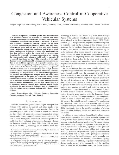
Congestion and Awareness Control in Cooperative<br />
Vehicular Systems<br />
Miguel Sepulcre, Jens Mittag, Paolo Santi, Member, IEEE, Hannes Hartenstein, Member, IEEE, Javier Gozalvez<br />
Abstract—Cooperative vehicular systems have been identified<br />
as a promising solution to overcome the current and future<br />
needs for increasing traffic safety and efficiency, while providing<br />
infotainment and added-value services on the move. To achieve<br />
their objectives, cooperative vehicular systems will be based<br />
on wireless communications between vehicles and with other<br />
infrastructure nodes, and will have to deal with highly dynamic<br />
nodes, challenging propagation conditions, and stringent application<br />
requirements. By looking at cooperative applications and<br />
their data traffic, as well as the current and foreseen spectrum<br />
allocations for cooperative vehicular systems, there is a risk that<br />
the corresponding radio channels could easily be saturated if<br />
no control algorithms are used. The saturation of the radio<br />
channels would result in unstable vehicular communications, and<br />
thus in an inefficient operation of cooperative systems. As a<br />
prime example of upcoming ubiquitous networks contributing<br />
to the vision of “a thousand radios per person”, cooperative<br />
vehicular systems need to be designed to scale to high densities<br />
of radios without centralized coordination, while at the same time<br />
guaranteeing the requirements of the implemented applications<br />
and services, for example the stringent needs of active traffic<br />
safety applications. In this paper, we survey and classify various<br />
decentralized methods to control the load on the radio channels<br />
and to ensure each vehicle’s capacity to detect and communicate<br />
with the relevant neighbouring vehicles, with a particular focus<br />
on approaches based on transmit power and rate control. Finally,<br />
we discuss the open research challenges that are imposed by<br />
different application requirements and potential existing contradictions.<br />
Index Terms—Cooperative Vehicular Systems, Congestion<br />
Control, Awareness Control, Power Control.<br />
I. INTRODUCTION<br />
Foreseen cooperative systems for Intelligent Transportation<br />
Systems (ITS) address the current and future needs of increasing<br />
traffic safety, efficiency and comfort. Despite the<br />
predicted growth rates in the number of motorized vehicles<br />
and the volume of transported goods, transportation should<br />
become safer, cleaner, more efficient and more comfortable. To<br />
help to reach these goals, cooperative vehicular systems will<br />
enable the direct exchange of information between vehicles,<br />
and between vehicles and Road Side Units (RSUs), using<br />
the IEEE 802.11p [1] technology on the 5.9GHz band. This<br />
M. Sepulcre is with the Uwicore Lab., University Miguel Hernandez of<br />
Elche, Spain (email: msepulcre@umh.es)<br />
J. Mittag is with the Institute of Telematics, Karlsruhe Institute of Technology,<br />
Germany (email: jens.mittag@kit.edu)<br />
P. Santi is with the Istituto di Informatica e Telematica del CNR, Italy<br />
(email: paolo.santi@iit.cnr.it)<br />
H. Hartenstein is with the Steinbuch Centre of Computing, Karlsruhe<br />
Institute of Technology, Karlsruhe, Germany (e-mail: hartenstein@kit.edu)<br />
J. Gozalvez is with the Uwicore Lab., University Miguel Hernandez of<br />
Elche, Spain (email: j.gozalvez@umh.es)<br />
technology is based on the CSMA/CA (Carrier Sense Multiple<br />
Access with Collision Avoidance) access protocol, and is<br />
being adapted to the European context in the ETSI ITS-G5<br />
standard [2]. The operation of cooperative vehicular systems<br />
is currently based on the exchange of two primary types of<br />
messages. On the one hand, Cooperative Awareness Messages<br />
(CAMs), also known as beacons, are broadcasted by all<br />
nodes on the so-called control channel, to provide and receive<br />
status information about the presence, geographical position<br />
and movement of neighoring nodes, and service announcements<br />
to/from those nodes. On the other hand, event-driven<br />
emergency messages are transmitted when an abnormal or<br />
dangerous situation is detected, in order to inform surrounding<br />
nodes about it.<br />
As the technology becomes more widely adopted, and<br />
cooperative applications and services are deployed, the shared<br />
radio channels could easily be saturated. It is well known<br />
from wireless local area networks based on CSMA/CA, that<br />
communication performance might not degrade gracefully if<br />
the network is saturated, but will in fact drop significantly<br />
once the maximum capacity is exceeded. Since the exchange<br />
of periodic CAMs alone could already saturate the channel,<br />
methods are required to control and limit the load on the<br />
radio channel. Congestion control has been studied in depth<br />
in various areas of computer networking. The term congestion<br />
control typically goes together with the Transport Control<br />
Protocol (TCP) of the Internet protocol suite. Here, cooperative<br />
control is used to ensure that each TCP connection gets a<br />
fair share of the available network resources. The mechanisms<br />
for congestion control in vehicular networks typically show<br />
analogous concepts, like decentralized control and fairness, but<br />
differ significantly due to the specific constraints of wireless<br />
communications in highly mobile and potentially harsh radio<br />
conditions.<br />
In addition to guaranteeing a channel load level that ensures<br />
stable system operation, cooperative vehicular systems will<br />
be required to ensure connectivity among the vehicular nodes<br />
imposed by the implemented applications. To ensure networkwide<br />
connectivity through the dynamic adaptation of each<br />
node’s transmission parameters, topology control protocols<br />
have been proposed for wireless ad-hoc and sensor networks<br />
[3]. However, the presence of highly dynamic vehicular<br />
mobility, along with the harsh radio propagation conditions<br />
strongly challenge the establishment of stable vehicular connections,<br />
and thus reduce the feasibility of traditional topology<br />
control protocols. In addition, cooperative vehicular systems<br />
do not require network-wide connectivity and the establishment<br />
of links in the traditional sense, but rather accurate<br />
1
000000000000000000000000000000000000000000000000000000000000000000000000000000000000000000000000000000000000000000000000000000000000000000000000000000000000000000000000000000000000000000000000000000000000000000000000000000000000000000000000000000000000000000000000000000000000000000000000000000000000000000000000000000000000000000000000000000000000000000000000000000000000000000000000000000000000000000000000000000000000000000000000000000000000000000000000000000000000000000000000000000000000000000000000000000000000000000000000000000000000000000000000000000000000000000000000000000000000000000000000000000000000000000000000000000<br />
000000000000000000000000000000000000000000000000000000000000000000000000000000000000000000000000000000000000000000000000000000000000000000000000000000000000000000000000000000000000000000000000000000000000000000000000000000000000000000000000000000000000000000000000000000000000000000000000000000000000000000000000000000000000000000000000000000000000000000000000000000000000000000000000000000000000000000000000000000000000000000000000000000000000000000000000000000000000000000000000000000000000000000000000000000000000000000000000000000000000000000000000000000000000000000000000000000000000000000000000000000000000000000000000000000<br />
000000000000000000000000000000000000000000000000000000000000000000000000000000000000000000000000000000000000000000000000000000000000000000000000000000000000000000000000000000000000000000000000000000000000000000000000000000000000000000000000000000000000000000000000000000000000000000000000000000000000000000000000000000000000000000000000000000000000000000000000000000000000000000000000000000000000000000000000000000000000000000000000000000000000000000000000000000000000000000000000000000000000000000000000000000000000000000000000000000000000000000000000000000000000000000000000000000000000000000000000000000000000000000000000000000<br />
000000000000000000000000000000000000000000000000000000000000000000000000000000000000000000000000000000000000000000000000000000000000000000000000000000000000000000000000000000000000000000000000000000000000000000000000000000000000000000000000000000000000000000000000000000000000000000000000000000000000000000000000000000000000000000000000000000000000000000000000000000000000000000000000000000000000000000000000000000000000000000000000000000000000000000000000000000000000000000000000000000000000000000000000000000000000000000000000000000000000000000000000000000000000000000000000000000000000000000000000000000000000000000000000000000<br />
000000000000000000000000000000000000000000000000000000000000000000000000000000000000000000000000000000000000000000000000000000000000000000000000000000000000000000000000000000000000000000000000000000000000000000000000000000000000000000000000000000000000000000000000000000000000000000000000000000000000000000000000000000000000000000000000000000000000000000000000000000000000000000000000000000000000000000000000000000000000000000000000000000000000000000000000000000000000000000000000000000000000000000000000000000000000000000000000000000000000000000000000000000000000000000000000000000000000000000000000000000000000000000000000000000<br />
000000000000000000000000000000000000000000000000000000000000000000000000000000000000000000000000000000000000000000000000000000000000000000000000000000000000000000000000000000000000000000000000000000000000000000000000000000000000000000000000000000000000000000000000000000000000000000000000000000000000000000000000000000000000000000000000000000000000000000000000000000000000000000000000000000000000000000000000000000000000000000000000000000000000000000000000000000000000000000000000000000000000000000000000000000000000000000000000000000000000000000000000000000000000000000000000000000000000000000000000000000000000000000000000000000<br />
000000000000000000000000000000000000000000000000000000000000000000000000000000000000000000000000000000000000000000000000000000000000000000000000000000000000000000000000000000000000000000000000000000000000000000000000000000000000000000000000000000000000000000000000000000000000000000000000000000000000000000000000000000000000000000000000000000000000000000000000000000000000000000000000000000000000000000000000000000000000000000000000000000000000000000000000000000000000000000000000000000000000000000000000000000000000000000000000000000000000000000000000000000000000000000000000000000000000000000000000000000000000000000000000000000<br />
000000000000000000000000000000000000000000000000000000000000000000000000000000000000000000000000000000000000000000000000000000000000000000000000000000000000000000000000000000000000000000000000000000000000000000000000000000000000000000000000000000000000000000000000000000000000000000000000000000000000000000000000000000000000000000000000000000000000000000000000000000000000000000000000000000000000000000000000000000000000000000000000000000000000000000000000000000000000000000000000000000000000000000000000000000000000000000000000000000000000000000000000000000000000000000000000000000000000000000000000000000000000000000000000000000<br />
000000000000000000000000000000000000000000000000000000000000000000000000000000000000000000000000000000000000000000000000000000000000000000000000000000000000000000000000000000000000000000000000000000000000000000000000000000000000000000000000000000000000000000000000000000000000000000000000000000000000000000000000000000000000000000000000000000000000000000000000000000000000000000000000000000000000000000000000000000000000000000000000000000000000000000000000000000000000000000000000000000000000000000000000000000000000000000000000000000000000000000000000000000000000000000000000000000000000000000000000000000000000000000000000000000<br />
000000000000000000000000000000000000000000000000000000000000000000000000000000000000000000000000000000000000000000000000000000000000000000000000000000000000000000000000000000000000000000000000000000000000000000000000000000000000000000000000000000000000000000000000000000000000000000000000000000000000000000000000000000000000000000000000000000000000000000000000000000000000000000000000000000000000000000000000000000000000000000000000000000000000000000000000000000000000000000000000000000000000000000000000000000000000000000000000000000000000000000000000000000000000000000000000000000000000000000000000000000000000000000000000000000<br />
000000000000000000000000000000000000000000000000000000000000000000000000000000000000000000000000000000000000000000000000000000000000000000000000000000000000000000000000000000000000000000000000000000000000000000000000000000000000000000000000000000000000000000000000000000000000000000000000000000000000000000000000000000000000000000000000000000000000000000000000000000000000000000000000000000000000000000000000000000000000000000000000000000000000000000000000000000000000000000000000000000000000000000000000000000000000000000000000000000000000000000000000000000000000000000000000000000000000000000000000000000000000000000000000000000<br />
000000000000000000000000000000000000000000000000000000000000000000000000000000000000000000000000000000000000000000000000000000000000000000000000000000000000000000000000000000000000000000000000000000000000000000000000000000000000000000000000000000000000000000000000000000000000000000000000000000000000000000000000000000000000000000000000000000000000000000000000000000000000000000000000000000000000000000000000000000000000000000000000000000000000000000000000000000000000000000000000000000000000000000000000000000000000000000000000000000000000000000000000000000000000000000000000000000000000000000000000000000000000000000000000000000<br />
000000000000000000000000000000000000000000000000000000000000000000000000000000000000000000000000000000000000000000000000000000000000000000000000000000000000000000000000000000000000000000000000000000000000000000000000000000000000000000000000000000000000000000000000000000000000000000000000000000000000000000000000000000000000000000000000000000000000000000000000000000000000000000000000000000000000000000000000000000000000000000000000000000000000000000000000000000000000000000000000000000000000000000000000000000000000000000000000000000000000000000000000000000000000000000000000000000000000000000000000000000000000000000000000000000<br />
000000000000000000000000000000000000000000000000000000000000000000000000000000000000000000000000000000000000000000000000000000000000000000000000000000000000000000000000000000000000000000000000000000000000000000000000000000000000000000000000000000000000000000000000000000000000000000000000000000000000000000000000000000000000000000000000000000000000000000000000000000000000000000000000000000000000000000000000000000000000000000000000000000000000000000000000000000000000000000000000000000000000000000000000000000000000000000000000000000000000000000000000000000000000000000000000000000000000000000000000000000000000000000000000000000<br />
000000000000000000000000000000000000000000000000000000000000000000000000000000000000000000000000000000000000000000000000000000000000000000000000000000000000000000000000000000000000000000000000000000000000000000000000000000000000000000000000000000000000000000000000000000000000000000000000000000000000000000000000000000000000000000000000000000000000000000000000000000000000000000000000000000000000000000000000000000000000000000000000000000000000000000000000000000000000000000000000000000000000000000000000000000000000000000000000000000000000000000000000000000000000000000000000000000000000000000000000000000000000000000000000000000<br />
000000000000000000000000000000000000000000000000000000000000000000000000000000000000000000000000000000000000000000000000000000000000000000000000000000000000000000000000000000000000000000000000000000000000000000000000000000000000000000000000000000000000000000000000000000000000000000000000000000000000000000000000000000000000000000000000000000000000000000000000000000000000000000000000000000000000000000000000000000000000000000000000000000000000000000000000000000000000000000000000000000000000000000000000000000000000000000000000000000000000000000000000000000000000000000000000000000000000000000000000000000000000000000000000000000<br />
000000000000000000000000000000000000000000000000000000000000000000000000000000000000000000000000000000000000000000000000000000000000000000000000000000000000000000000000000000000000000000000000000000000000000000000000000000000000000000000000000000000000000000000000000000000000000000000000000000000000000000000000000000000000000000000000000000000000000000000000000000000000000000000000000000000000000000000000000000000000000000000000000000000000000000000000000000000000000000000000000000000000000000000000000000000000000000000000000000000000000000000000000000000000000000000000000000000000000000000000000000000000000000000000000000<br />
000000000000000000000000000000000000000000000000000000000000000000000000000000000000000000000000000000000000000000000000000000000000000000000000000000000000000000000000000000000000000000000000000000000000000000000000000000000000000000000000000000000000000000000000000000000000000000000000000000000000000000000000000000000000000000000000000000000000000000000000000000000000000000000000000000000000000000000000000000000000000000000000000000000000000000000000000000000000000000000000000000000000000000000000000000000000000000000000000000000000000000000000000000000000000000000000000000000000000000000000000000000000000000000000000000<br />
000000000000000000000000000000000000000000000000000000000000000000000000000000000000000000000000000000000000000000000000000000000000000000000000000000000000000000000000000000000000000000000000000000000000000000000000000000000000000000000000000000000000000000000000000000000000000000000000000000000000000000000000000000000000000000000000000000000000000000000000000000000000000000000000000000000000000000000000000000000000000000000000000000000000000000000000000000000000000000000000000000000000000000000000000000000000000000000000000000000000000000000000000000000000000000000000000000000000000000000000000000000000000000000000000000<br />
000000000000000000000000000000000000000000000000000000000000000000000000000000000000000000000000000000000000000000000000000000000000000000000000000000000000000000000000000000000000000000000000000000000000000000000000000000000000000000000000000000000000000000000000000000000000000000000000000000000000000000000000000000000000000000000000000000000000000000000000000000000000000000000000000000000000000000000000000000000000000000000000000000000000000000000000000000000000000000000000000000000000000000000000000000000000000000000000000000000000000000000000000000000000000000000000000000000000000000000000000000000000000000000000000000<br />
000000000000000000000000000000000000000000000000000000000000000000000000000000000000000000000000000000000000000000000000000000000000000000000000000000000000000000000000000000000000000000000000000000000000000000000000000000000000000000000000000000000000000000000000000000000000000000000000000000000000000000000000000000000000000000000000000000000000000000000000000000000000000000000000000000000000000000000000000000000000000000000000000000000000000000000000000000000000000000000000000000000000000000000000000000000000000000000000000000000000000000000000000000000000000000000000000000000000000000000000000000000000000000000000000000<br />
000000000000000000000000000000000000000000000000000000000000000000000000000000000000000000000000000000000000000000000000000000000000000000000000000000000000000000000000000000000000000000000000000000000000000000000000000000000000000000000000000000000000000000000000000000000000000000000000000000000000000000000000000000000000000000000000000000000000000000000000000000000000000000000000000000000000000000000000000000000000000000000000000000000000000000000000000000000000000000000000000000000000000000000000000000000000000000000000000000000000000000000000000000000000000000000000000000000000000000000000000000000000000000000000000000<br />
000000000000000000000000000000000000000000000000000000000000000000000000000000000000000000000000000000000000000000000000000000000000000000000000000000000000000000000000000000000000000000000000000000000000000000000000000000000000000000000000000000000000000000000000000000000000000000000000000000000000000000000000000000000000000000000000000000000000000000000000000000000000000000000000000000000000000000000000000000000000000000000000000000000000000000000000000000000000000000000000000000000000000000000000000000000000000000000000000000000000000000000000000000000000000000000000000000000000000000000000000000000000000000000000000000<br />
000000000000000000000000000000000000000000000000000000000000000000000000000000000000000000000000000000000000000000000000000000000000000000000000000000000000000000000000000000000000000000000000000000000000000000000000000000000000000000000000000000000000000000000000000000000000000000000000000000000000000000000000000000000000000000000000000000000000000000000000000000000000000000000000000000000000000000000000000000000000000000000000000000000000000000000000000000000000000000000000000000000000000000000000000000000000000000000000000000000000000000000000000000000000000000000000000000000000000000000000000000000000000000000000000000<br />
000000000000000000000000000000000000000000000000000000000000000000000000000000000000000000000000000000000000000000000000000000000000000000000000000000000000000000000000000000000000000000000000000000000000000000000000000000000000000000000000000000000000000000000000000000000000000000000000000000000000000000000000000000000000000000000000000000000000000000000000000000000000000000000000000000000000000000000000000000000000000000000000000000000000000000000000000000000000000000000000000000000000000000000000000000000000000000000000000000000000000000000000000000000000000000000000000000000000000000000000000000000000000000000000000000<br />
000000000000000000000000000000000000000000000000000000000000000000000000000000000000000000000000000000000000000000000000000000000000000000000000000000000000000000000000000000000000000000000000000000000000000000000000000000000000000000000000000000000000000000000000000000000000000000000000000000000000000000000000000000000000000000000000000000000000000000000000000000000000000000000000000000000000000000000000000000000000000000000000000000000000000000000000000000000000000000000000000000000000000000000000000000000000000000000000000000000000000000000000000000000000000000000000000000000000000000000000000000000000000000000000000000<br />
000000000000000000000000000000000000000000000000000000000000000000000000000000000000000000000000000000000000000000000000000000000000000000000000000000000000000000000000000000000000000000000000000000000000000000000000000000000000000000000000000000000000000000000000000000000000000000000000000000000000000000000000000000000000000000000000000000000000000000000000000000000000000000000000000000000000000000000000000000000000000000000000000000000000000000000000000000000000000000000000000000000000000000000000000000000000000000000000000000000000000000000000000000000000000000000000000000000000000000000000000000000000000000000000000000<br />
000000000000000000000000000000000000000000000000000000000000000000000000000000000000000000000000000000000000000000000000000000000000000000000000000000000000000000000000000000000000000000000000000000000000000000000000000000000000000000000000000000000000000000000000000000000000000000000000000000000000000000000000000000000000000000000000000000000000000000000000000000000000000000000000000000000000000000000000000000000000000000000000000000000000000000000000000000000000000000000000000000000000000000000000000000000000000000000000000000000000000000000000000000000000000000000000000000000000000000000000000000000000000000000000000000<br />
Fig. 1. Highway scenario with a traffic jam in one direction of driving and<br />
free flow conditions in the other direction. This example represents a typical<br />
traffic situation in which congestion control and awareness control protocols<br />
might be needed.<br />
and updated data on each vehicle’s local environment (e.g.<br />
position, speed and direction of movement of neighboring<br />
vehicles) to support upper-layer protocols and cooperative<br />
applications. In this context, this paper defines awareness<br />
control protocols as those techniques aimed at ensuring each<br />
vehicle’s capacity to detect, and possibly communicate with<br />
the relevant vehicles and infrastructure nodes present in their<br />
local neighborhood, through the dynamic adaptation of their<br />
transmission parameters. Awareness control protocols can, for<br />
example, adapt each vehicle’s transmission power to successfully<br />
transmit a message at a given distance, or dynamically<br />
modify each vehicle’s packet generation rate to increase the<br />
probability of receiving at least one packet at a certain distance<br />
during a given time window. Given their similarities,<br />
awareness control can be seen as a geo-localized adaptation<br />
of topology control.<br />
Based on the previous definitions and their fundamentally<br />
different objectives, congestion and awareness control can be<br />
easily differentiated. For instance, congestion control aims to<br />
limit the observed load on the wireless channel for all nodes<br />
in order to provide fair and harmonized access to the wireless<br />
medium. As such, congestion control algorithms reduce the<br />
transmission power or rate of all nodes in order to avoid<br />
scenarios in which neighboring nodes, which are part of the<br />
same traffic situation, use (on average) significantly different<br />
power levels or beaconing rates. Considering the example<br />
illustrated in Figure 1, the high density of vehicles in the<br />
traffic-congested area would require the use of congestion<br />
control protocols to control and limit the channel load. Unlike<br />
congestion control protocols, awareness control algorithms<br />
adjust the power or rate of only a selected subset of nodes,<br />
with the objective of fulfilling the requirements of a particular<br />
application. In the scenario illustrated in Figure 1, the<br />
requirements of the applications run by the vehicles in the<br />
traffic jam are notably different from those of the applications<br />
run by the vehicles under free-flow conditions moving in the<br />
opposite direction, with different speeds and distances between<br />
neighbouring vehicles. For example, while vehicles under freeflow<br />
conditions would require their communication settings to<br />
allow for a safe lane-change maneuver, such a maneuver could<br />
be completely unexpected, or be less dangerous, for vehicles in<br />
the traffic jam. Awareness control protocols would be therefore<br />
required to dynamically adapt each vehicle’s communications<br />
parameters to efficiently satisfy their individual requirements.<br />
In this context, this paper focuses on congestion and<br />
awareness-control techniques with a special emphasis on<br />
transmit power control and application-driven design policies.<br />
Recently, various researchers contributed approaches and performance<br />
evaluations that address the issues of controlling the<br />
load on the radio channel, and guaranteeing each vehicle’s<br />
capacity to communicate with its local neighborhood. In this<br />
paper, we survey various key approaches and key findings<br />
in a coherent manner to present and categorize the pool of<br />
ideas for upcoming standardization and deployment activities.<br />
We will discuss in some detail three approaches based on<br />
transmit power control, one targeting the issue of congestion<br />
control, and two addressing an efficient awareness control.<br />
The paper is structured accordingly. We first introduce some<br />
background information in Section II, followed by a discussion<br />
of congestion and awareness control through the perspective<br />
of control theory in Section III. In Section IV, we survey<br />
congestion control approaches that have been proposed for<br />
vehicular communications, and discuss in detail a proposal<br />
based on transmit power control, in addition to evaluating its<br />
performance vs. effectiveness trade-offs. Section V surveys<br />
key contributions to awareness control, before discussing geoopportunistic<br />
and traffic contextual approaches designed to<br />
ensure the strict requirements imposed by cooperative applications,<br />
in particular traffic safety applications. Section VI<br />
discusses open research challenges deriving from the joint<br />
study of congestion and awareness control protocols, as well as<br />
multi-application scenarios. Finally, Section VII summarizes<br />
the main contributions made by this paper.<br />
II. BACKGROUND<br />
A first generation of future cooperative vehicular systems<br />
will be based on the IEEE 802.11p standard, according to<br />
current standardization activities. As such, previous studies<br />
dealing with congestion and awareness control have been<br />
performed on top of IEEE 802.11p. In order to support the<br />
explanations and descriptions given in the following sections<br />
and to clarify the system setup and the assumptions made in<br />
this paper, we will briefly elaborate on the relevant aspects of<br />
the communication system for cooperative vehicular systems.<br />
IEEE 802.11p [1] is specified to operate in the 5.9 GHz<br />
frequency band. At the MAC (Medium Access Control) layer,<br />
it employs the CSMA/CA mechanism to coordinate medium<br />
access by multiple stations. In CSMA/CA, each station has<br />
to listen to the channel and check whether it is free before<br />
being allowed to transmit. This operation is called carrier<br />
sensing, and it is performed by comparing the detected energy<br />
on the channel with a pre-defined threshold, called the carrier<br />
sensing threshold. The region of space where a certain ongoing<br />
transmission can be detected by a device tentatively accessing<br />
the channel is called the carrier sensing region. Note that, in<br />
general, this region has irregular shape due to non-isotropic<br />
radio signal propagation. However, it is a common practice<br />
in the wireless networking literature to consider the carrier<br />
sensing region as nearly circular, hence the notion of carrier<br />
sensing range used to refer to the distance up to which an<br />
ongoing transmission can be sensed by a device attempting<br />
to access the channel. If the channel is busy, the station has<br />
to defer, wait until the channel is free again and choose a<br />
random backoff timer that determines the additional waiting<br />
2
time that has to elapse after the channel is sensed idle. Despite<br />
the backoff mechanism, two or more stations can transmit<br />
simultaneously, therefore producing a packet collision and<br />
a possible data loss due to interferences. In particular, two<br />
stations can transmit simultaneously mainly due to the well<br />
known hidden-terminal problem. The hidden-terminal problem<br />
occurs when two (or more) stations cannot detect each other’s<br />
transmissions, but their transmission ranges are not disjoint. It<br />
has been widely studied in the literature.<br />
Due to its robustness against fast fading channels, the<br />
IEEE 802.11p amendment adapts the OFDM (Orthogonal Frequency<br />
Division Multiplexing) transmission technology used<br />
in IEEE 802.11a and g, with the exception that 10 Mhz instead<br />
of 20 MHz channels are used by default. The reduction from<br />
20 Mhz to 10 Mhz was necessary to account for the increased<br />
Doppler and RMS delay spreads (as reported by [4] or<br />
[5]) which would otherwise lead to inter-symbol interference<br />
(ISI) and inter-carrier interference (ICI), and thus significantly<br />
challenge the successful reception of packets. Apart from the<br />
problem of ISI and ICI, a receiver is also challenged by the<br />
fast fading channel conditions that are observable due to the<br />
high relative mobility of vehicles. For instance, the coherence<br />
time of the channel, i.e. the time during which the channel<br />
impulse response is essentially invariant, can be smaller than<br />
the duration of a single packet transmission [6], which could<br />
result in an increased probability of bit and packet errors. This<br />
is an issue, since the IEEE 802.11p frame format provides<br />
only a preamble to fully estimate the channel and only four<br />
pilot sub-carriers to partially track the state of the channel [7].<br />
Hence, the initial estimate can become invalid at the end of the<br />
reception leading to an increased probability of bit and packet<br />
errors [6]. As a consequence, the channel impulse response of<br />
two consecutive packet transmissions will most likely not be<br />
correlated, and the channel can only be considered symmetric<br />
for an instant of time, but not for slightly different timestamps.<br />
By symmetric, we mean that the propagation characteristics<br />
of the radio channel are approximately the same in both<br />
directions of the wireless communication link.<br />
As defined by the Federal Communications Commission of<br />
the USA (FCC) [8], a spectrum of 75 MHz has been allocated<br />
at 5.9 GHz. Similarly, a spectrum of 50 MHz has been allocated<br />
at the same frequency band in Europe. In both cases, the<br />
entire spectrum is divided into several 10 MHz channels, out<br />
of which one channel, commonly called the Control Channel<br />
(CCH), is used as a reference for the exchange of safety-related<br />
information. The remaining channels are known as service<br />
channels and are used for safety and non-safety applications.<br />
The data rates provided by IEEE 802.11p [1] with such 10 Mhz<br />
channels range from 3 to 27 Mbps. While the lower data<br />
rates are the most robust ones and require lower signal-tointerference<br />
and noise ratio to correctly decode a packet,<br />
higher data rates come with the benefit of reduced transmission<br />
times, and thus with the possible gain of a reduced packet<br />
collision probability in situations of higher channel loads.<br />
Obviously, there is trade-off between increased robustness and<br />
reduced congestion. To investigate this trade-off, a simulation<br />
study was performed in [9] in order to determine the most<br />
robust data rate for broadcast communication. The study’s<br />
Level Max. density Avg. Speed Vehicles within<br />
of Service (vehicles/km/lane) (km/h) 1000 m comm. range<br />
A 7 100.0 84<br />
B 11 100.0 132<br />
C 16 98.4 192<br />
D 22 91.5 264<br />
E 25 88.0 300<br />
TABLE I<br />
THE CAPACITY OF MULTILANE HIGHWAYS AND THE CORRESPONDING<br />
AVERAGE SPEEDS ACCORDING TO [10]. IN ADDITION, THE NUMBER OF<br />
VEHICLES WITHIN THE COMMUNICATION RANGE ARE LISTED FOR A 3<br />
LANE PER DIRECTION HIGHWAY AND A 1000 M COMMUNICATION RANGE.<br />
results reveal that a 6 Mbps data rate turns out to be the<br />
best selection for safety related communication. Since recent<br />
standardization activities [2] have taken up these findings, we<br />
will assume a fixed data rate of 6 Mbps in the rest of this<br />
paper.<br />
Apart from the key technology characteristics, it is also important<br />
to understand how it is envisioned that the cooperative<br />
vehicular system will operate and what its dimensions will<br />
be. According to the common agreement among researchers<br />
and industry, vehicles will periodically broadcast cooperative<br />
awareness messages (CAM) in order to establish a mutual<br />
awareness. CAM messages provide information on positioning,<br />
speed, and heading, among other fields. The establishment<br />
of a mutual awareness can be considered the fundamental<br />
safety service in cooperative vehicular systems, on top of<br />
which advanced safety applications, e.g. cooperative forward<br />
collision warning or intersection collision warning, will be<br />
deployed. However, in order to fulfill the requirements of<br />
such advanced safety applications, the transmitted information<br />
might need to be updated several times per second, possibly<br />
requiring a periodic CAM rate of up to ten messages per<br />
second [11]–[13]. Hence, solely the establishment of a mutual<br />
awareness could saturate and congest the wireless channel,<br />
especially according to the following considerations. First,<br />
each CAM message could have a size of between 250 and<br />
800 Bytes, due to digital signatures and certificates that secure<br />
and authenticate the information contained in those messages.<br />
Second, the communication system is expected to cover distances<br />
of up to 1000 m. And third, vehicle densities of up<br />
to 25 vehicles/km/lane are not an exception (cf. the reported<br />
capacity of multilane highways as listed in Table I). As a<br />
result, the total amount of traffic generated per second for<br />
mutual awareness could easily exceed the available data rate of<br />
6 Mbps. As a consequence, the performance of the communication<br />
system will degrade significantly if no countermeasures<br />
are taken.<br />
III. A CONTROL THEORY APPROACH<br />
The process of restricting the load on the wireless channel,<br />
and thereby the congestion in the wireless network, and<br />
the process of adapting the communications parameters to<br />
guarantee a certain awareness level are very closely related<br />
to traditional control theory. In particular, due to the shared<br />
wireless communication channel and the lack of a centralized<br />
3
Traffic<br />
Situation<br />
input<br />
parameter<br />
target<br />
description<br />
Objective<br />
Controller<br />
1<br />
2 3<br />
Result<br />
action<br />
optional feedback<br />
Fig. 2. Analysis of congestion and awareness control algorithms from a<br />
control-theory-based perspective. In general a controller adapts the transmission<br />
parameters, based on its objective and the detected traffic situation,<br />
in order to achieve a particular result. Optionally, the controller makes use<br />
of some sort of feedback with regard to the observed result to optimize its<br />
performance. Depending on the objective (1), e.g. a network-wide limitation<br />
of the channel load or an awareness-range requirement, the scope of the openor<br />
closed-loop controller (2) is either global or local. Consequently, optional<br />
feedback (4) about the result can come from the network or from individual<br />
nodes only (3).<br />
coordination entity in vehicular communications, both processes<br />
are representatives of the distributed control discipline.<br />
For instance, congestion in the network can not be avoided or<br />
reduced if only one single node is decreasing its transmission<br />
power and/or rate, and more importantly, the result of the<br />
selected action can not be observed by the node itself, but only<br />
by its neighbors. That implies that all nodes should — at least,<br />
for an optimal and reliable control — act cooperatively and<br />
provide feedback about the result of their actions to each other.<br />
Similarly, the success of an increased transmission power with<br />
regard to a desired awareness range can only be determined<br />
by the receiving node, and not by the transmitter itself.<br />
Due to the relationship of congestion and awareness control<br />
to traditional control theory, this paper discusses existing proposals<br />
for congestion and awareness control with respect to the<br />
concepts and notions typically used in control theory. For this<br />
purpose, both methods are analyzed and compared according<br />
to the general framework sketched in Figure 2: an algorithm<br />
might use some sort of detection to classify the traffic situation<br />
or scenario which the node is currently in, and which might be<br />
used proactively by the controller as feedforward input. The<br />
controller itself decides how the transmission will be adjusted,<br />
of course depending on the situation and the corresponding<br />
target description, i.e. the current objective. The selected action<br />
then leads to an observable result, which can be fed back to<br />
the controller in order to improve its accuracy.<br />
Based on Figure 2, particular control algorithms are also<br />
classified into open- and closed-loop controllers. The former<br />
do not make use of feedback to correct and optimize the<br />
decisions made in the past, and typically incorporate a system<br />
model to derive the actions to be taken. The advantage of such<br />
a control loop is the nonexisting overhead, but, obviously, the<br />
performance and robustness of such a controller depends on<br />
the accuracy of the system model used. On the contrary, closed<br />
loop controllers employ feedback to determine how well<br />
the objective has been achieved. An often used closed loop<br />
controller is the generic Proportional-Integral-Derivative (PID)<br />
controller, which uses the present error (P), the accumulation<br />
of past errors (I), a prediction of future errors (D), or only a<br />
subset of those measures to control the system. Compared with<br />
4<br />
open loop controllers, closed-loop controllers can improve the<br />
control due to the use of feedback data, at the cost of communications<br />
overhead. In addition, and particularly if a generic<br />
PID controller is used, they do not incorporate any system<br />
model, have no direct knowledge of the underlying process<br />
and perform poorly in non-linear systems. With respect to<br />
feedback, it is also necessary to distinguish between explicit<br />
feedback, i.e., first-order feedback with regard to the desired<br />
result, and implicit feedback, i.e., second-order feedback that<br />
is obtained by using different observations that are to some<br />
extent correlated to the actual observation. A possible implicit<br />
feedback could be, for instance, the locally observed number<br />
of neighbors or MAC layer reception statistics.<br />
Another important aspect is how the design objective can<br />
be quantified and how the achievement of the objective is<br />
measured. When awareness control protocols are used, the<br />
objective could be defined as the reliability with which a<br />
certain vehicle’s awareness range is guaranteed. However, for<br />
congestion control, the question of how to describe the objective<br />
is more difficult to answer, since more than one metric<br />
for channel congestion exists, and all have their advantages<br />
and disadvantages. For instance, the use of a metric such as<br />
the channel busy time ratio, i.e., the fraction of time during<br />
which the channel is considered busy by the access layer, or<br />
the channel load, i.e., the fraction of time during which the<br />
sensed energy exceeds a specific threshold, cannot account<br />
for overlapping transmissions, but has the advantage of being<br />
easily implementable by the communication hardware. On the<br />
other hand, a metric such as the beaconing load [14], though<br />
it does quantify the amount of overlapping packets, is not<br />
directly measurable by the hardware.<br />
IV. CONGESTION CONTROL<br />
Congestion control techniques for vehicular communications<br />
can be classified according to several criteria. The major<br />
classification criterion considers the information base from<br />
which congestion control mechanisms derive their decision<br />
to adjust the transmission parameters. The first class, which<br />
in the literature is sometimes also referred to as reactive<br />
congestion control, uses first-order information about the channel<br />
congestion status to decide whether and how an action<br />
should be undertaken. Due to their nature, actions to lessen<br />
channel load are undertaken only after a congested situation<br />
has been detected. Using control theory terminology, reactive<br />
congestion control approaches can be classified as an instance<br />
of feedback control mechanisms. The second class, sometimes<br />
also referred to as proactive congestion control, uses models<br />
that, based on information such as number of nodes in the<br />
vicinity and data generation patterns, try to estimate transmission<br />
parameters which will not lead to congested channel<br />
conditions, while at the same time providing the desired<br />
application-level performance. In particular, such mechanisms<br />
typically employ a system model to estimate the channel load<br />
under a given set of transmission parameters, and make use of<br />
optimization algorithms to determine the maximum transmit<br />
power and/or rate setting that will adhere to a maximum<br />
congestion limit. Using control theory terminology, proactive<br />
4
congestion control approaches can be classified as an instance<br />
of feedforward control mechanisms.<br />
Another criterion used to classify congestion control techniques<br />
is what type of information is used to feed the control<br />
system, which is typically only locally available information,<br />
or also information provided by neighboring vehicles – dubbed<br />
distributed information in the following.<br />
Finally, existing solutions can further be classified with<br />
reference to the means through which congestion is controlled,<br />
which is typically achieved by adjusting the transmission<br />
power, the packet generation rate, the carrier sense threshold<br />
or a combination of a subset of the transmission parameters.<br />
Let us start briefly discussing the relative advantages and<br />
disadvantages of proactive vs. reactive approaches. Given their<br />
ability to prevent congestion, proactive approaches are very<br />
appealing for vehicular environments, where radio communications<br />
are primarily used for safety applications, whose<br />
performance would be seriously threatened by congested channel<br />
conditions. However, proactive approaches come with two<br />
major drawbacks. First, in order to estimate the expected load<br />
generated by neighboring vehicles, such approaches require<br />
a communication model that maps individual transmission<br />
power levels to deterministic carrier sense ranges. However,<br />
this mapping is reasonable only as long as it reflects the<br />
average propagation conditions of the wireless channel. Thus,<br />
propagation conditions should be either dynamically estimated<br />
as the vehicle moves, which is very difficult to do in a<br />
practical scenario, or they should be statistically estimated<br />
to build specific profiles for different environments, e.g.,<br />
urban and highway. A second major drawback of proactive<br />
approaches is the need to carefully estimate the amount of<br />
generated application-layer traffic in a certain period of time.<br />
Although in some cases this is indeed possible (e.g, in the<br />
case of applications built on top of periodic beacon exchange),<br />
accurate application-layer traffic estimation is a challenging<br />
task in general.<br />
Reactive approaches, which do not suffer of the drawbacks<br />
that accompany proactive mechanisms, nonetheless have the<br />
notable disadvantage of undertaking control actions only after<br />
a congested channel condition has been detected. Considering<br />
that some time is needed to recover from a congested channel<br />
situation, this means that reactive approaches expose safetyrelated<br />
applications to the risk of not being able to fulfill<br />
their design goal, due to the poor (temporary) performance<br />
of the underlying radio channel. Another disadvantage of<br />
reactive approaches is that important design goals such as<br />
fairness and packet prioritization are more difficult to achieve<br />
than in a proactive approach. We remark that fairness is<br />
important in vehicular networks to ensure that all vehicles<br />
in the network have similar opportunities to communicating<br />
with nearby nodes. In fact, if congestion control were to be<br />
obtained by sacrificing, say, a specific node in the network is<br />
forced to set its transmission power to a very low value, this<br />
node would not have a chance to communicate with nodes<br />
in its surrounding, impairing application-level performance.<br />
Most importantly, in safety-related applications, every vehicle<br />
in the network should be able to receive fresh information<br />
about the status of the other vehicles in the surrounding, as<br />
well as to communicate its own status to the surrounding<br />
vehicles. Hence, fairness becomes a major design goal in<br />
safety-related applications. As for prioritization, providing a<br />
strict prioritization of different classes of packets is an important<br />
requirement for vehicular networking, which is partly<br />
addressed in the drafted IEEE 802.11p standard by adopting<br />
the EDCA (Enhanced Distributed Channel Access) mechanism<br />
defined within IEEE 802.11e.<br />
A. Related Work<br />
Before describing a relevant congestion control approach,<br />
we briefly survey the most representative studies aimed at optimizing<br />
the packet generation rate and transmission power of<br />
beaconing applications. While this body of work is not directly<br />
concerned with controlling congestion on the wireless channel,<br />
it has the merit of giving very useful insights into the effects<br />
of varying rate and transmission power on beaconing performance.<br />
These insights can be considered as knowledge base<br />
upon which state-of-the-art congestion control approaches are<br />
built. Further, with respect to the literal interpretation of<br />
congestion control in this paper, those approaches might rather<br />
be termed congestion reduction techniques, which, on their<br />
own, are of course able to reduce the number of messages<br />
transmitted to the channel, but which are not actually able to<br />
effectively avoid congested and overloaded channel conditions.<br />
In [15], the authors present a performance evaluation study<br />
of cooperative collision warning applications based on periodic<br />
beaconing. The major contribution made by this study is<br />
the introduction of a novel parameter to measure the performance<br />
of cooperative collision warning applications, namely<br />
the packet inter-reception time. This metric, defined as the<br />
time elapsed between two successful reception events at a<br />
vehicle referring to beacons sent by another, specific vehicle,<br />
is motivated by the observation that what is relevant for active<br />
safety applications is the freshness of the status information<br />
gathered from surrounding vehicles. Thus, a few consecutive<br />
failed receptions are much more harmful to active safety<br />
applications than are several scattered failed receptions. After<br />
introducing the novel metric, the authors go on to perform an<br />
extensive simulation-based performance study on the effects<br />
of using different beacon generation rates and transmission<br />
power values on the packet inter-reception time.<br />
In [16], the authors investigate the effect of different beaconing<br />
strategies on active safety application performance.<br />
More specifically, the authors consider tracking accuracy as<br />
the performance metric, which is defined as the error (as<br />
perceived by the active safety application) in tracking the<br />
positions of neighboring vehicles. After having defined the<br />
performance metric, the authors present different beaconing<br />
strategies aimed at minimizing tracking error, and identify an<br />
adaptive beaconing policy with repetitions as the best performing<br />
one. According to this policy, a beacon is sent only if the<br />
predicted tracking error of the own position at surrounding<br />
vehicles exceeds a threshold. If the threshold is exceeded, the<br />
beacon is sent a few times (the number of repetitions is a<br />
tunable parameter) to increase the probability that the beacon<br />
is correctly received by neighboring vehicles, thus improving<br />
5
tracking accuracy. As mentioned in the beginning of this<br />
section, such a mechanism will help to reduce the congestion,<br />
but it does not control the congestion of the channel in the<br />
first place.<br />
Another example of congestion reduction can be found in<br />
[17]. The authors focus on emergency warning messages, that<br />
are sent whenever a vehicle shows an abnormal behavior (e.g.,<br />
it broke down and is blocking the road/lane, or it lost control<br />
and it is changing lanes unexpectedly). The authors aim of<br />
optimizing the transmission of warning messages is based on<br />
the observation that messages should be repeatedly sent out<br />
until the “abnormal” behavior stops and the vehicle returns to<br />
“normal” behavior. The authors further state that if several abnormal<br />
vehicles are sending out emergency warning messages<br />
at a constant rate, the average delivery delay will increase<br />
rapidly due to channel congestion. Consequently, the number<br />
of simultaneous emergency warning transmissions should be<br />
carefully controlled. To achieve this goal, the authors propose<br />
a “multiplicative rate decreasing algorithm”, which decreases<br />
the retransmission rate of an emergency warning message over<br />
time. As a result, several emergency warning messages can be<br />
served and delivered by the system with limited delay. The<br />
above transmission strategy is further optimized by defining<br />
strategies to freeze the generation of emergency messages<br />
when certain conditions are met (e.g., redundant transmissions<br />
from following vehicles).<br />
According to the terminology defined in Section III, the<br />
approach of [17] belongs to the class of proactive approaches,<br />
and acts on packet generation rate to prevent congestion. Yet,<br />
the approach of [17] is mostly an open-loop controller, since<br />
the multiplicative rate decreasing algorithm that is used to<br />
tune the packet generation rate is based only on predicted<br />
performance based on suitable models of the communication<br />
channel. On the other hand, a form of primary feedback (e.g.,<br />
reception of redundant transmissions from following vehicles)<br />
is used in the decision rules to freeze emergency message<br />
transmission.<br />
Apart from the cited studies above, other congestion reduction<br />
solutions that adapt the transmission power and generation<br />
rate based on the current velocity exist as well (e.g. [18],<br />
[19]). Since the paper focuses on actual congestion control<br />
techniques, we will skip their detailed presentation here and<br />
instead survey a collection of representative congestion control<br />
approaches for cooperative vehicular systems. One of these<br />
approaches, called Distributed Fair Power Adjustment for<br />
Vehicular Environments or D-FPAV [20], will be described<br />
in detail in the next section.<br />
On the reactive side of congestion control, Khorakhun et. al<br />
developed an algorithm that adjusts either the transmission<br />
power or the packet generation rate with relation to the locally<br />
measured channel busy time ratio [21]. The channel busy time<br />
is the fraction of time during which the channel was sensed<br />
busy. Depending on whether the local measurement is below<br />
or above a pre-defined threshold, the transmission power or<br />
generation rate is either increased or decreased by one step.<br />
In order to achieve a higher level of fairness, the authors stated<br />
that it is necessary to exchange the local measurements among<br />
neighboring vehicles, and allow an increase of the transmission<br />
power/rate only if the currently used value is below the average<br />
power/rate configuration used by the vehicle’s neighbors.<br />
Compared with proactive approaches, this reactive approach<br />
is not able to avoid congestion on the wireless channel, and<br />
supports no prioritization of different classes of messages. In<br />
addition, a simple analysis shows that the proposed algorithm<br />
is not able to prevent oscillations in the adjustment process.<br />
The issue is systematic and fundamental: since not all vehicles<br />
perform the transmit power adjustment at the same point in<br />
time, it can easily happen that the transmit power reduction at<br />
a few nodes leads to a reduced channel busy time observation<br />
from the perspective of neighboring nodes that have yet not<br />
reduced their transmit power. As a result, those nodes will<br />
possibly increase their transmit power (instead of decreasing<br />
it as well), and amplify the transmit power reduction of nodes<br />
that have already decreased their transmit power. It is obvious<br />
that some sort of additional feedback is needed to indicate the<br />
reason why the measured channel busy time has decreased or<br />
to determine who should reduce first.<br />
A hybrid approach that attempts to combine the advantages<br />
of both proactive and reactive approaches was proposed by<br />
Baldessari et. al in [22]. Their solution consists of an improved<br />
rate control, an improved power control and a combined<br />
power and rate control algorithm, all of which use channel<br />
busy time observations to derive the number of neighbors in<br />
the surrounding area (optionally, also through an additional<br />
exchange of local vehicle density estimations). Based on the<br />
number of neighbors and a pre-defined channel busy time<br />
threshold, the authors then either derive a packet generation<br />
rate directly, or start with a fixed packet generation rate and<br />
derive the maximum transmission power which will not violate<br />
the threshold. In the latter case, the authors assume that the<br />
vehicles in the surrounding area are distributed uniformly and,<br />
typical for a proactive approach, make use of a communication<br />
model that maps carrier sense ranges to individual transmission<br />
power levels.<br />
Another hybrid congestion control approach was recently<br />
proposed in [23], where the authors adaptively change both<br />
beacon generation rate (in a proactive way) and transmission<br />
power (in a reactive way) with the goal of reducing channel<br />
congestion, and consequently improving a vehicle’s ability to<br />
accurately track the position of surrounding vehicles. Two<br />
slightly different control approaches are applied to the tuning<br />
of beacon generation rate and transmission power. Beacon<br />
generation rate is tuned based on a predicted tracking error<br />
of own position. The prediction accounts for channel<br />
unreliability, i.e. packet losses, by including the observed<br />
fraction of successfully received beacons sent by surrounding<br />
vehicles. Thus, a closed-loop feedforward controller based on<br />
secondary feedback is used for setting the beacon generation<br />
rate. Additionally, transmission power control is applied based<br />
on the observed channel status (more specifically, based on the<br />
channel busy time). This part of the algorithm is thus a closedloop<br />
feedback controller based on secondary feedback. Note<br />
that both beacon generation rate and transmission power use<br />
information locally available at the vehicles (i.e., direct observations)<br />
to control transmission parameters. As a consequence,<br />
this mechanism bears the same fundamental issue observed for<br />
6
[21]: without knowing the channel congestion status of the<br />
surrounding nodes, the transmission power adaptation mechanism<br />
cannot know why the channel is no longer congested<br />
and which vehicle should reduce or increase its power value<br />
first.<br />
B. Contribution<br />
In this section, we present the Distributed-Fair Power Adjustment<br />
for Vehicular Environments (D-FPAV) approach to<br />
proactive, distributed congestion control in vehicular environments.<br />
D-FPAV achieves congestion control by varying<br />
the node transmission power, where a node’s transmit power<br />
setting depends on predictions of application-layer traffic and<br />
the observed number of vehicles in the surrounding.<br />
D-FPAV is designed to pursue all the optimization goals<br />
described in the previous sub-section:<br />
1. congestion control: limit the load on the wireless medium<br />
in order to prevent congestion generated by applicationlayer<br />
traffic. The metric used to assess the effectiveness of<br />
congestion control is channel access time. Furthermore,<br />
the authors show the benefits of congestion control on<br />
the performance of multi-hop emergency message propagation.<br />
2. fairness: maximize the minimum transmit power value<br />
over all transmission power levels assigned to the nodes<br />
forming the vehicular network, subject to Goal 1.<br />
3. prioritization: improve the basic IEEE 802.11 EDCA<br />
mechanism to provide a better prioritization of higher<br />
priority over lower priority messages.<br />
We observe that the D-FPAV approach is aimed at limiting<br />
the amount of traffic that is generated by vehicles, with the<br />
goal of keeping this load under a specified congestion limit<br />
(the MAL value defined in the following). By tuning the<br />
congestion limit, the optimal point of the “interference level”<br />
vs. “reception rate” tradeoff can be found. The optimal tuning<br />
of this tradeoff is however out of D-FPAV scope.<br />
The D-FPAV protocol is periodically executed on the nodes<br />
forming the vehicular network, in order to adjust node transmission<br />
power in response to changes in the network topology<br />
or application-layer traffic patterns. Before presenting D-FPAV,<br />
we introduce some notation and basic definitions. We denote<br />
by N = {u1,...,un} the set of nodes in the vehicular<br />
network. Each of these nodes can set its transmission power<br />
in the interval [Pm,PM], where Pm is the minimum and<br />
PM is the maximum possible transmission power. Given a<br />
set N of nodes as above, a power assignment function PA<br />
for N is a function that assigns to every node ui ∈ N a<br />
value PA(i) ∈ [0,1]. The power used by node ui to send<br />
application-layer messages is pi = Pm+PA(i)·(PM −Pm).<br />
For any nodeui in the network, we useCS(PA,i) to denote<br />
the carrier sensing range of node ui at transmission power<br />
pi = Pm+PA(i)·PM , and CS(MAX,i) to denote the same<br />
range at maximum transmission power PM.<br />
A fundamental notion in D-FPAV is that of Applicationlayer<br />
Load (AL) generated by a node, and of Channel Load<br />
(CL) experienced by a node under a certain power assignment<br />
Algorithm D-FPAV: (algorithm for node ui)<br />
INPUT: AL of all the nodes in CS(MAX,i)<br />
OUTPUT: a power setting PA(i) for node ui, such that<br />
the resulting power assignment is an optimal<br />
solution to CCF<br />
I(MAX,i) denotes the set of nodes uj such that<br />
ui ∈ CS(MAX,j)<br />
1. Based on the AL of the nodes in CS(MAX,i),<br />
compute the maximum common tx power level<br />
Pi s.t. the MAL threshold is not violated at any<br />
node in CS(MAX,i)<br />
2a.Disseminate Pi to all nodes in CS(MAX,i)<br />
2b. Collect the power level values computed by<br />
nodes uj ∈ I(MAX,i); store the received values in Pj<br />
3. Compute the final power level:<br />
PA(i) = min Pi,minu j∈I(MAX,i){Pj} <br />
Fig. 3. The D-FPAV algorithm.<br />
PA. Formally, AL(i) denotes the application-layer load (expressed<br />
in bytes/sec) that node ui is expected to generate<br />
in the next period, where the period represents the interval<br />
of time before the next D-FPAV execution. Based on these<br />
definitions, the CL experienced by a node ui can then be<br />
computed based on the AL generated by the nodes in the<br />
surrounding as follows:<br />
CL(PA,i) = <br />
AL(j) ,<br />
uj∈I(PA,i)<br />
where I(PA,i) = {uj ∈ N : ui ∈ CS(PA,j)}.<br />
The intuition behind our definition of channel load is that<br />
the load observed at ui can be estimated as the sum of the<br />
application-layer load generated by nodes in the set I(PA,i),<br />
i.e., those nodes having ui within carrier sensing range at the<br />
current transmit power levels. This is because a transmission<br />
from a node in set I(PA,i) prevents ui from accessing the<br />
channel.<br />
The Congestion Control under Fairness constraints (CCF)<br />
problem we are attempting to solve is defined as follows:<br />
Definition 1 (CCF problem): Given a set N =<br />
{u1,...,un} of nodes, and a value MAL of the Maximum<br />
Application-layer Load admitted on the wireless channel<br />
(expressed in bytes/sec), solve the following optimization<br />
problem<br />
⎧⎨<br />
maxPA∈PA(minui∈N PA(i))<br />
subject to<br />
,<br />
⎩<br />
CL(PA,i) ≤ MAL ∀i ∈ {1,...,n}<br />
where PA is the set of all possible power assignments.<br />
Solving CCF addresses design goals 1 and 2 above, where<br />
MAL (a choice of the network designer) is used to control the<br />
congestion generated by application-layer load. As we show<br />
in the following, goal 3. can be achieved by transmitting lowpriority<br />
messages using the transmit power computed solving<br />
CCF, and by transmitting high-priority messages at maximum<br />
power.<br />
The D-FPAV algorithm is reported in Figure 3, and is<br />
composed of the following steps: i) gather information about<br />
AL for nodes within (maximum) carrier sense range; ii)<br />
7
ased on i), locally execute the FPAV algorithm from [14]<br />
to compute the optimal CCF solution for the nodes within<br />
(maximum) carrier sense range; iii) exchange the locally computed<br />
transmission power values with surrounding vehicles;<br />
iv) select the minimum transmission power value among the<br />
one locally computed and those computed by surrounding<br />
vehicles in order to build the network-wide optimal solution<br />
to CCF.<br />
The FPAV algorithm of [14] is a centralized algorithm based<br />
on the well-known “max-min” principle: the transmission<br />
power of all vehicles in a surrounding area is ‘virtually’<br />
increased step-by-step (starting at lowest possible power level),<br />
while estimating the resulting application load at each vehicle<br />
after each step. As long as the MAL threshold is not violated<br />
at any vehicle, and the maximum allowed transmission power<br />
has not been reached, power levels are further increased. Upon<br />
termination, FPAV has thus computed the highest common<br />
transmission power level which did not violate the MAL<br />
parameter in the whole network.<br />
In [20], it is formally proven that D-FPAV computes an<br />
optimal solution to CCF under the following assumptions: a)<br />
carrier sense ranges of nodes are symmetric; b) each node is<br />
able to accurately estimate the AL for the next period; and<br />
c) each node is able to gather AL information from all nodes<br />
within maximum carrier sense range. In practical scenarios,<br />
these assumptions are unlikely to hold, due to the complexity<br />
of the propagation environment (a), and difficulties in accurately<br />
predicting AL and gathering AL information (b) and<br />
(c). Yet, in [20] it is shown through extensive simulation that<br />
D-FPAV successfully solves the CCF problem at least when<br />
assumption c) is released, i.e., when nodes have only partial<br />
knowledge of the AL generated by nodes within maximum<br />
CS range.<br />
In [20], D-FPAV is evaluated in a scenario 1 in which<br />
application-layer load at each node is generated by a beaconing<br />
application, which periodically generates packets to report<br />
vehicle status to nodes in the surrounding area. Beacon messages<br />
are considered low-priority messages in this scenario,<br />
and transmitted using D-FPAV computed transmission power<br />
with lowest EDCA priority class. Besides beaconing messages,<br />
event-driven emergency messages are randomly generated<br />
within the network. These are high-priority messages that are<br />
seldom generated, and, given their safety-critical nature, are<br />
not subject to congestion control. Emergency messages are<br />
sent at maximum transmission power PM using the highest<br />
priority EDCA traffic class.<br />
An important issue to understand in the D-FPAV approach<br />
is the tradeoff between accuracy of channel load estimation on<br />
a vehicle, and additional overhead which is put on the channel.<br />
In fact, as the carrier sense range is typically larger than the<br />
transmission range, the only way to acquire knowledge about<br />
presence of vehicles located outside the transmission range is<br />
by making use of a multi-hop strategy, i.e., having vehicles retransmit<br />
the position of their neighbors. Clearly, propagating<br />
this information in a multi-hop manner puts an additional load<br />
1 For details on the simulation scenario, including features of the radio<br />
environment, please see [20].<br />
Probability Of Message Reception<br />
1<br />
0.8<br />
0.6<br />
0.4<br />
0.2<br />
0<br />
Event-driven D-FPAV-On<br />
Event-driven D-FPAV-Off<br />
Beacon D-FPAV-On<br />
Beacon D-FPAV-Off<br />
100 200 300 400 500 600 700 800 900 1000<br />
Distance to Sender [m]<br />
Fig. 4. Probability of successful reception of periodic beacon and emergency<br />
messages at varying distances. MAL is set to 2.5Mb/s.<br />
on the channel, which can be considered as control overhead.<br />
In order to optimally tune the above described tradeoff, the<br />
following design decisions have to be made: how often the<br />
status of neighboring vehicles should be forwarded, what range<br />
of neighbors must be included, and which transmission power<br />
must be used to transmit this information.<br />
The following strategies have been considered in [20]:<br />
piggyback the aggregated status information (position of surrounding<br />
vehicles) to 1) each beacon, 2) every 5th beacon or<br />
3) every 10th beacon, and transmit it with power PA(i) (the<br />
transmit power value as computed by D-FPAV). The authors<br />
found that piggybacking aggregate status information in 1 out<br />
of 10 beacon messages results in the best compromise between<br />
control overhead and effectiveness of congestion control.<br />
The probability of correctly receiving a beacon or emergency<br />
message as a function of distance with and without<br />
D-FPAV is reported in Figure 4. As seen from the figure,<br />
EDCA alone is not sufficient to clearly prioritize emergency<br />
over beacon messages. On the other hand, D-FPAV achieves<br />
a clear prioritization of emergency over beacon messages,<br />
i.e. emergency messages have a consistently higher reception<br />
probability in the whole range of transmission distances. It<br />
is also interesting to observe that D-FPAV congestion control<br />
mechanism has beneficial effects not only on high priority<br />
traffic, but also on low-priority traffic (beacons): in fact, their<br />
reception probability at close distances from the transmitter<br />
(within 150m) is considerably higher than when no congestion<br />
control exists.<br />
The effectiveness of the D-FPAV approach in achieving<br />
fair channel access opportunities is shown in Figure 5, which<br />
reports the channel access time of vehicles as a function of<br />
their position on the road: without D-FPAV, channel access<br />
time depends highly on the density of vehicles in the surroundings,<br />
and it is thus unfairly distributed. On the other hand,<br />
when D-FPAV is active, the load generated by the beaconing<br />
application is kept under control, and channel access time is<br />
nearly constant throughout the network.<br />
In a follow-up study [24], we showed that in order to<br />
effectively guarantee a strict enforcement of an upper channel<br />
load limit and to provide fairness with respect to channel<br />
access opportunities, it is necessary to propagate the position<br />
8
Channel Access Time [s]<br />
0.08<br />
0.07<br />
0.06<br />
0.05<br />
0.04<br />
0.03<br />
0.02<br />
0.01<br />
D-FPAV Off<br />
D-FPAV On<br />
0<br />
1000 2000 3000 4000 5000 6000 7000<br />
X-Position on Highway<br />
Fig. 5. Average channel access time experienced by periodic beacon<br />
messages as a function of vehicle position on the highway. MAL is set to<br />
2.5Mb/s.<br />
of neighbor vehicles for at least two hops. As described above,<br />
the D-FPAV protocol provides this information by piggybacking<br />
this information only in 1 out of 10 beacon messages in<br />
order to reduce the overhead, yet, the overhead can still grow<br />
to 40 % – compared to the actual AL data. In [24], we therefore<br />
developed a distributed algorithm that adjusts the transmission<br />
power based on averaged values for the neighbor information<br />
instead of using detailed neighbor information about each<br />
single node. By using only this averaged information, we were<br />
able to reduce the overhead down to less than 1 %, at the cost<br />
of only slighty exceeding the pre-defined MAL limit.<br />
C. Standardization<br />
In Europe, congestion control in vehicular communications<br />
is considered to be a building block and seen as mandatory<br />
in order to guarantee a reliable communication performance<br />
for safety-related applications. This was acknowledged by the<br />
Car-2-Car Communication Consortium (C2C-CC) as early as<br />
in 2009 through the establishment of a task force on transmit<br />
power control. The results from this task force have helped<br />
to persuade the European Commission to establish a Specialist<br />
Task Force (STF) on the configuration and validation<br />
of decentralued congestion control methods for Intelligent<br />
Transportation Systems (ITS) and techniques to enable the coexistence<br />
of cooperative ITS and Dedicated Short Range Communication<br />
(DSRC) within the European Telecommunications<br />
Standard Institute (ETSI). Since March 2010, the STF with<br />
its six experts from the industry and research community have<br />
been working on a technical specification for a standardized<br />
congestion control algorithm to be used by ITS.<br />
The specification defines a mandatory basic congestion<br />
control algorithm based on a controller that uses no feedback<br />
and only information that is locally available. In addition, the<br />
specification describes an enhanced control algorithm that uses<br />
feedback from neighboring nodes, e.g. their observed channel<br />
load and their currently used transmit power. Both approaches<br />
will use the channel load metric to define the congestion limit,<br />
since it can be implemented by the hardware.<br />
V. AWARENESS CONTROL<br />
Following the previous discussions, awareness control techniques<br />
are aimed at ensuring each vehicle’s capacity to detect<br />
as well as to communicate with the relevant vehicles in their<br />
local neighbourhood. Awareness control protocols are needed<br />
to reliably and efficiently support higher-layer protocols and<br />
applications, for example, ensuring that traffic safety applications<br />
obtain, at a minimum, the level of awareness that is<br />
required to detect dangerous traffic situations in advance and<br />
act accordingly.<br />
Cooperative vehicular systems impose very stringent application<br />
requirements, with most of the applications being<br />
supported by the periodic exchange of beacons. It is generally<br />
assumed in the literature that the cooperative application<br />
requirements can be defined in terms of dissemination area (or<br />
range), latency (or delay) and reliability [25]. This extends the<br />
preliminary requirements defined by VSC [26] and ETSI [27],<br />
which consider only some of these requirements. While the<br />
dissemination area can be defined as the geographic area<br />
where a given message should be received, the latency is<br />
the maximum allowed delay to deliver such message, and<br />
the reliability is the minimum probability of receiving such a<br />
message (usually estimated during a certain time window). The<br />
requirements imposed by cooperative applications represent<br />
the basis of awareness control protocols.<br />
A. Related Work<br />
Initial studies have been conducted to evaluate the communications<br />
and applications performance in VANETs, and<br />
serve as fundamental studies for the design of awareness<br />
control protocols. For example, the work in [28] presents a<br />
performance and sensitivity analysis of different MAC layer<br />
protocols, based on the idea of repetitive transmissions over<br />
CSMA. In this work, the authors propose that a packet be<br />
retransmitted multiple times during its lifetime, and study<br />
different repetition mechanisms by means of simulation and<br />
a detailed mathematical anlalysis. The conducted study identifies<br />
the operating and communications conditions (number<br />
of interferers and packet generation rates) under which the<br />
application requirements are satisfied and the channel load is<br />
maintained under a certain limit. In [15], the authors conduct<br />
a performance evaluation study of cooperative collision warning<br />
applications under different traffic densities, and explore<br />
different packet generation rates and transmission ranges.<br />
The conducted study shows the importance of considering<br />
appropriate metrics to evaluate the performance of cooperative<br />
applications, such as latency or packet inter-reception time.<br />
This observation results from the importance of the freshness<br />
of the information received from surrounding vehicles. The<br />
relevance of adequately evaluating the performance of cooperative<br />
vehicular systems has also been emphasized in other<br />
studies. For example, the work in [29] highlights the need to<br />
differentiate communication and application performance or<br />
reliability. In particular, in [29] the authors demonstrate the<br />
suitability of cooperative vehicular systems to improve traffic<br />
safety based on real-world experimental data on highways.<br />
9
Following the control-theory perspective discussed in Section<br />
III, awareness control protocols can be classified as<br />
open-loop or closed-loop approaches, and can use implicit<br />
or explicit feedback. Different existing open-loop awareness<br />
control protocols use power-range maps to dynamically adapt<br />
each vehicle’s transmission power as a function of its transmission<br />
range requirements. For example, the work in [30]<br />
proposes an OPportunistic-driven adaptive RAdio resource<br />
Management (OPRAM) mechanism, that adapts each vehicle’s<br />
transmission parameters to reliably and efficiently exchange a<br />
message before reaching a critical safety area, for example an<br />
intersection. The OPRAM mechanism is an application-driven<br />
awareness control protocol that is based on radio propagation<br />
estimates to dynamically calculate the required transmission<br />
power levels as a function of the distance to the critical safety<br />
area. Despite having been designed as a power-range map<br />
based technique, OPRAM could be evolved to dynamically<br />
adapt the transmission power and packet generation rate to<br />
the experienced channel load, in order to compensate for<br />
the negative effects of packet collisions on the application’s<br />
reliability. OPRAM will be described in detail in the next<br />
section.<br />
Multi-hop beaconing protocols represent an alternative<br />
open-loop solution for awareness control. With these protocols,<br />
broadcast messages transmitted by a vehicle are relayed<br />
by neighboring vehicles to achieve the target probability of<br />
reception at high distances within the required delay. In [31],<br />
the Multi-Hop Vehicular Broadcast (MHVB) protocol is intended<br />
to efficiently relay broadcast packets over multiple<br />
hops, and satisfy the target dissemination area within the<br />
allowable latency. With MHVB, only the vehicle that correctly<br />
receives a given broadcast message and is located at the<br />
highest distance from the transmitter will relay such message.<br />
A similar approach was proposed in [32], where a vehicle can<br />
relay multiple beacons during its lifetime in a single packet<br />
as long as it has received each one of these beacons less<br />
than a established maximum number of times. With multihop<br />
beaconing protocols, the beacon’s transmission power<br />
was able to be reduced compared to single hop beaconing<br />
protocols. In this context, the work in [33] compares singlehop<br />
and multi-hop beaconing protocols. This study shows<br />
that under simplified propagation and multi-hop operating<br />
conditions, the channel load in multi-hop beaconing protocols<br />
can be reduced using packet multiplexing techniques. With<br />
these techniques, when a vehicle has to relay a broadcast<br />
packet it will attach its own broadcast packet to the relayed<br />
message. However, in realistic environments where packets<br />
can be lost due to radio channel errors and packet collisions,<br />
the reduction of the channel load obtained with multi-hop<br />
beaconing cannot be achieved. It is worth mentioning that,<br />
in scenarios where obstacles block the radio signal, such as<br />
buildings or trucks, multi-hop beaconing protocols could be<br />
required to successfully satisfy the application requirements.<br />
Closed-loop awareness control protocols make use of exchanged<br />
broadcast messages to dynamically adapt to the varying<br />
propagation and channel load conditions. In some existing<br />
solutions, the feedback is implicitly obtained from received<br />
messages without the need to transmit extra information. An<br />
example of closed-loop solution with implicit feedback is the<br />
work in [34], in which the authors propose the use of the<br />
received messages to estimate in real-time the path loss or<br />
average signal attenuation, by subtracting the power estimated<br />
at the receiver from the transmitted power (included by default<br />
in the header of all beacons in cooperative vehicular systems).<br />
The proposed algorithm dynamically selects the power and<br />
data rate required to successfully transmit a packet to a given<br />
vehicle, while minimising the interference generated to other<br />
vehicles. In the joint rate-power control algorithm proposed<br />
in [23], two different control approaches are applied to adapt<br />
the packet generation rate and the transmission power. In order<br />
to detect abnormal driving maneuvers in advance, the packet<br />
generation rate is dynamically adapted to bound the longitudinal<br />
and lateral position tracking errors of surrounding vehicles.<br />
A new packet is transmitted when the estimated tracking<br />
error of surrounding vehicles exceeds a certain threshold. To<br />
estimate the tracking error, the algorithm takes into account<br />
the channel reliability by dynamically estimating the packet<br />
error probability from the packets received from surrounding<br />
vehicles. The transmission power is adapted based on the<br />
observed channel status. Considering Lmin and Lmax as<br />
the lower/upper transmission range bounds dictated by the<br />
safety applications, the transmission range is linearly adapted<br />
between Lmin and Lmax as a function of the experienced<br />
channel load. The transmission power is then calculated considering<br />
power-range maps based on empirical measurements.<br />
Other closed-loop awareness control solutions are based on<br />
explicit feedback. In this case, vehicles inform each other<br />
about the correct reception of messages at a certain distance.<br />
Using this explicit information, vehicles can decide whether<br />
they should increase or decrease their transmission power<br />
and/or packet generation rate. For example, the work in [35]<br />
includes the target range of the packet, and the IDs of the<br />
nodes from which a message was successfully received when<br />
their separation distance was larger than the target range, as<br />
extra information in the beacon’s header. When a vehicle<br />
receives more than N beacons containing its ID, it decreases<br />
its transmission power, since at least N vehicles beyond the<br />
target range are receiving its broadcast messages. This type of<br />
closed-loop technique depends heavily on the correct reception<br />
of a beacon to adequately adapt its operational parameters.<br />
As a result, if some of these messages are not correctly<br />
received, for example due to packet collisions under high<br />
traffic densities, the vehicles can incorrectly increase their<br />
transmission power and augment packet collisions.<br />
The accuracy or precision of the awareness information<br />
received from surrounding nodes is also analysed in different<br />
protocols proposed in the literature. A representative example<br />
is reported in [16], where the authors propose an openloop<br />
approach through which the packet generation rate is<br />
dynamically adapted to bound the tracking errors of surrounding<br />
vehicles. To this end, a new packet is transmitted by a<br />
vehicle only when its movement changes (speed, heading,<br />
etc.). In this case, the authors propose that each of these<br />
packets be retransmitted several times to ensure its reception<br />
by surrounding vehicles, which results in a decrease of the<br />
tracking error in realistic propagation environments, at the<br />
10
expense of increasing the channel load. In fact, as shown<br />
in [36], the increase of the packet generation rate can augment<br />
the probability of successfully receiving a packet at the target<br />
distance within the required time window, as long as the<br />
channel load is maintained at reasonable levels. In particular,<br />
the work reported in [36] proposes the rapid rebroadcasting<br />
of each packet during its lifetime to increase its probability<br />
of reception, extending the work presented in [28]. To this<br />
aim, various rebroadcasting schemes are proposed based on<br />
different open-loop strategies: synchronous and asynchronous<br />
designs, repetition with and without carrier sensing, fixed<br />
number, and p-persistent repetition. A different perspective is<br />
reported in [37] with regard to the accuracy of the awareness<br />
information required by each vehicle. The work in [37] considers<br />
that the packet generation rate should depend on each<br />
vehicle’s mobility characteristics, and those of the vehicles<br />
surrounding it, as well as the traffic context/situation. In<br />
particular, the authors propose the use of situation-adaptive<br />
beaconing to achieve adequate levels of accuracy or updated<br />
awareness information received from neighboring vehicles.<br />
B. Contribution<br />
The consideration of application requirements in the design<br />
of awareness control protocols for cooperative vehicular<br />
systems is particularly important due to the critical nature of<br />
safety applications. A basic application-driven awareness control<br />
approach is summarized in Figure 6. Its operation is based<br />
on each vehicle’s application requirements. As an example, in<br />
the case of an intersection collision warning application, the<br />
requirements would correspond to the minimum distance to the<br />
intersection at which two potentially colliding vehicles need<br />
to exchange a message to alert the driver with sufficient time<br />
to avoid the accident. Since such requirements depend heavily<br />
on the vehicles’ position, speed and acceleration, each vehicle<br />
would need to continuously adapt its application requirements<br />
based on its positioning and movement information. Once<br />
the application requirements have been updated, each vehicle<br />
will accordingly modify its communications parameters (e.g.<br />
transmission power and packet generation rate) to satisfy them<br />
with certain reliability imposed by the application (papp).<br />
The adaptation of the communications parameters could be<br />
based on some of the protocols and algorithms described in<br />
the previous section. While this basic approach could satisfy<br />
the required vehicle’s awareness level, the following sections<br />
describe two application-driven awareness control approaches<br />
aimed at further improving the communications efficiency<br />
through the use of geographic and traffic context information.<br />
1) Geo-Opportunistic approach: OPRAM [30] is an example<br />
of an application-driven awareness control technique<br />
aimed at efficiently adapting each vehicle’s communications<br />
parameters (transmission power and packet generation rate) to<br />
guarantee the transmission range and reliability requirements<br />
imposed by traffic applications. To further improve the efficiency<br />
of the basic awareness control approach previously discussed,<br />
OPRAM proposes a geo-opportunistic approach that<br />
makes use of the geographic positioning and the knowledge<br />
of potentially critical safety areas. To illustrate its operation<br />
Basic application-driven awareness control approach<br />
INPUT: Established application reliability papp<br />
OUTPUT: A power and rate setting for vehicle i, such that<br />
the resulting assignment satisfies the application<br />
requirements<br />
1. Update positioning and movement information.<br />
2. Adapt application requirements.<br />
3. Obtain required power and rate based on papp<br />
and application requirements.<br />
Fig. 6. Basic application-driven awareness control approach.<br />
and benefits, an intersection collision warning application is<br />
considered here. However, OPRAM’s operation could be easilly<br />
adapted to other applications such as cooperative merging<br />
assistance and left turn assistance applications.<br />
Intersection collision warning applications in urban intersections<br />
represent one of the most challenging scenarios for<br />
awareness control protocols due to the strict traffic safety<br />
application requirements and the challenging non-line-of-sight<br />
propagation conditions. In a typical intersection scenario, two<br />
approaching vehicles A and B might collide at the intersection<br />
due to the driver’s lack of attention, wrong/hidden traffic<br />
signals, or any other reason that could provoke the accident<br />
despite the driver’s ability and perception capabilities (see<br />
Figure 7). To detect each other’s presence, the two vehicles<br />
periodically broadcast beacon messages. The intersection collision<br />
warning application requires that both vehicles exchange<br />
at least one packet before the critical distance (CD). The<br />
CD distance is the minimum distance to the intersection at<br />
which a vehicle needs to receive a broadcast message from<br />
a the potentially colliding vehicle to alert the driver of a<br />
potential road danger with sufficient time to react, and stop<br />
before reaching the intersection. The CD distance typically<br />
depends on the vehicle’s speed, the driver’s reaction time and<br />
the vehicle’s emergency deceleration. The presence of buildings<br />
may require the use of high transmission power levels<br />
and/or packet generation rates to guarantee the communication<br />
between the two vehicles before the target distance CD, and<br />
hence avoid the potential accident. However, the constant use<br />
of high transmission powers and rates by multiple vehicles<br />
could create channel congestion, and increase the system’s<br />
instability. To reduce the channel load while satisfying the<br />
application requirements, OPRAM is designed to dynamically<br />
increase the transmission power and packet rate of each vehicle<br />
only in a small region beforeCD, called the Algorithm Region<br />
(AR), as illustrated in Figure 7. With this geo-opportunistic<br />
increase, OPRAM aims to guarantee with high probability the<br />
correct reception of at least one packet from a potentially<br />
colliding vehicle before reaching CD, while minimizing the<br />
overall channel load. Outside AR, OPRAM operates with<br />
a low transmission power, sufficient to communicate with<br />
the vehicles moving along the same street in line-of-sight<br />
propagation conditions. The definition of theAR region allows<br />
OPRAM to adapt its communication parameters only when<br />
approaching a critical safety area, such as an intersection, lane<br />
merging zones, entrance ramps, blind curves, etc.<br />
11
Position of B<br />
00000000000000000000000000000000000000000000000000000000000000000000000000000<br />
00000000000000000000000000000000000000000000000000000000000000000000000000000<br />
B<br />
00000000000000000000000000000000000000000000000000000000000000000000000000000<br />
00000000000000000000000000000000000000000000000000000000000000000000000000000<br />
00000000000000000000000000000000000000000000000000000000000000000000000000000<br />
00000000000000000000000000000000000000000000000000000000000000000000000000000<br />
00000000000000000000000000000000000000000000000000000000000000000000000000000<br />
00000000000000000000000000000000000000000000000000000000000000000000000000000<br />
00000000000000000000000000000000000000000000000000000000000000000000000000000<br />
00000000000000000000000000000000000000000000000000000000000000000000000000000<br />
00000000000000000000000000000000000000000000000000000000000000000000000000000<br />
00000000000000000000000000000000000000000000000000000000000000000000000000000<br />
00000000000000000000000000000000000000000000000000000000000000000000000000000<br />
00000000000000000000000000000000000000000000000000000000000000000000000000000<br />
00000000000000000000000000000000000000000000000000000000000000000000000000000<br />
00000000000000000000000000000000000000000000000000000000000000000000000000000<br />
00000000000000000000000000000000000000000000000000000000000000000000000000000<br />
00000000000000000000000000000000000000000000000000000000000000000000000000000<br />
00000000000000000000000000000000000000000000000000000000000000000000000000000<br />
00000000000000000000000000000000000000000000000000000000000000000000000000000<br />
00000000000000000000000000000000000000000000000000000000000000000000000000000<br />
00000000000000000000000000000000000000000000000000000000000000000000000000000<br />
00000000000000000000000000000000000000000000000000000000000000000000000000000<br />
00000000000000000000000000000000000000000000000000000000000000000000000000000<br />
00000000000000000000000000000000000000000000000000000000000000000000000000000<br />
00000000000000000000000000000000000000000000000000000000000000000000000000000<br />
00000000000000000000000000000000000000000000000000000000000000000000000000000<br />
00000000000000000000000000000000000000000000000000000000000000000000000000000<br />
00000000000000000000000000000000000000000000000000000000000000000000000000000<br />
00000000000000000000000000000000000000000000000000000000000000000000000000000<br />
00000000000000000000000000000000000000000000000000000000000000000000000000000<br />
00000000000000000000<br />
00000000000000000000000000000000000000000000000000000000000000000000000000000<br />
000000000000000000<br />
00000000000000000000000000000000000000000000000000000000000000000000000000000000000000000000000000000000000000000000000000000000000000000000000000000000000000000000000000000000000000000000000000000000000000000000000000000000000000000000000000000000000000000000000000000000000000000000000000000000000000000000000000000000000000000000000000000000000000000000000000000000000000000000000000000000000000000000000000000000000000000000000000000000000000000000000000000000000000<br />
00000000000000000000000000000000000000000000000000000000000000000000000000000<br />
00000000000000000000000000000000000000000000000000000000000000000000000000000<br />
00000000000000000000<br />
00000000000000000000000000000000000000000000000000000000000000000000000000000000000000000000000000000000000000000000000000000000000000000000000000000000000000000000000000000000000000000000000000000000000000000000000000000000000000000000000000000000000000000000000000000000000000000000000000000000000000000000000000000000000000000000000000000000000000000000000000000000000000000000000000000000000000000000000000000000000000000000000000000000000000000000000000000000000000<br />
000000000000000000<br />
00000000000000000000<br />
000000000000000000<br />
00000000000000000000000000000000000000000000000000000000000000000000000000000000000000000000000000000000000000000000000000000000000000000000000000000000000000000000000000000000000000000000000000000000000000000000000000000000000000000000000000000000000000000000000000000000000000000000000000000000000000000000000000000000000000000000000000000000000000000000000000000000000000000000000000000000000000000000000000000000000000000000000000000000000000000000000000000000000000<br />
00000000000000000000000000000000000000000000000000000000000000000000000000000<br />
00000000000000000000000000000000000000000000000000000000000000000000000000000<br />
00000000000000000000<br />
00000000000000000000000000000000000000000000000000000000000000000000000000000000000000000000000000000000000000000000000000000000000000000000000000000000000000000000000000000000000000000000000000000000000000000000000000000000000000000000000000000000000000000000000000000000000000000000000000000000000000000000000000000000000000000000000000000000000000000000000000000000000000000000000000000000000000000000000000000000000000000000000000000000000000000000000000000000000000<br />
000000000000000000<br />
00000000000000000000<br />
000000000000000000<br />
00000000000000000000000000000000000000000000000000000000000000000000000000000000000000000000000000000000000000000000000000000000000000000000000000000000000000000000000000000000000000000000000000000000000000000000000000000000000000000000000000000000000000000000000000000000000000000000000000000000000000000000000000000000000000000000000000000000000000000000000000000000000000000000000000000000000000000000000000000000000000000000000000000000000000000000000000000000000000<br />
00000000000000000000000000000000000000000000000000000000000000000000000000000<br />
00000000000000000000000000000000000000000000000000000000000000000000000000000<br />
00000000000000000000<br />
00000000000000000000000000000000000000000000000000000000000000000000000000000000000000000000000000000000000000000000000000000000000000000000000000000000000000000000000000000000000000000000000000000000000000000000000000000000000000000000000000000000000000000000000000000000000000000000000000000000000000000000000000000000000000000000000000000000000000000000000000000000000000000000000000000000000000000000000000000000000000000000000000000000000000000000000000000000000000<br />
000000000000000000<br />
00000000000000000000<br />
000000000000000000<br />
00000000000000000000000000000000000000000000000000000000000000000000000000000000000000000000000000000000000000000000000000000000000000000000000000000000000000000000000000000000000000000000000000000000000000000000000000000000000000000000000000000000000000000000000000000000000000000000000000000000000000000000000000000000000000000000000000000000000000000000000000000000000000000000000000000000000000000000000000000000000000000000000000000000000000000000000000000000000000<br />
00000000000000000000000000000000000000000000000000000000000000000000000000000<br />
00000000000000000000000000000000000000000000000000000000000000000000000000000<br />
00000000000000000000<br />
00000000000000000000000000000000000000000000000000000000000000000000000000000000000000000000000000000000000000000000000000000000000000000000000000000000000000000000000000000000000000000000000000000000000000000000000000000000000000000000000000000000000000000000000000000000000000000000000000000000000000000000000000000000000000000000000000000000000000000000000000000000000000000000000000000000000000000000000000000000000000000000000000000000000000000000000000000000000000<br />
000000000000000000<br />
00000000000000000000<br />
000000000000000000<br />
00000000000000000000000000000000000000000000000000000000000000000000000000000000000000000000000000000000000000000000000000000000000000000000000000000000000000000000000000000000000000000000000000000000000000000000000000000000000000000000000000000000000000000000000000000000000000000000000000000000000000000000000000000000000000000000000000000000000000000000000000000000000000000000000000000000000000000000000000000000000000000000000000000000000000000000000000000000000000<br />
00000000000000000000000000000000000000000000000000000000000000000000000000000<br />
00000000000000000000000000000000000000000000000000000000000000000000000000000<br />
00000000000000000000<br />
00000000000000000000000000000000000000000000000000000000000000000000000000000000000000000000000000000000000000000000000000000000000000000000000000000000000000000000000000000000000000000000000000000000000000000000000000000000000000000000000000000000000000000000000000000000000000000000000000000000000000000000000000000000000000000000000000000000000000000000000000000000000000000000000000000000000000000000000000000000000000000000000000000000000000000000000000000000000000<br />
000000000000000000<br />
00000000000000000000<br />
000000000000000000<br />
00000000000000000000000000000000000000000000000000000000000000000000000000000000000000000000000000000000000000000000000000000000000000000000000000000000000000000000000000000000000000000000000000000000000000000000000000000000000000000000000000000000000000000000000000000000000000000000000000000000000000000000000000000000000000000000000000000000000000000000000000000000000000000000000000000000000000000000000000000000000000000000000000000000000000000000000000000000000000<br />
00000000000000000000000000000000000000000000000000000000000000000000000000000<br />
00000000000000000000000000000000000000000000000000000000000000000000000000000<br />
00000000000000000000<br />
00000000000000000000000000000000000000000000000000000000000000000000000000000<br />
000000000000000000<br />
00000000000000000000000000000000000000000000000000000000000000000000000000000000000000000000000000000000000000000000000000000000000000000000000000000000000000000000000000000000000000000000000000000000000000000000000000000000000000000000000000000000000000000000000000000000000000000000000000000000000000000000000000000000000000000000000000000000000000000000000000000000000000000000000000000000000000000000000000000000000000000000000000000000000000000000000000000000000000<br />
00000000000000000000000000000000000000000000000000000000000000000000000000000<br />
000000000000000000<br />
00000000000000000000<br />
00000000000000000000000000000000000000000000000000000000000000000000000000000000000000000000000000000000000000000000000000000000000000000000000000000000000000000000000000000000000000000000000000000000000000000000000000000000000000000000000000000000000000000000000000000000000000000000000000000000000000000000000000000000000000000000000000000000000000000000000000000000000000000000000000000000000000000000000000000000000000000000000000000000000000000000000000000000000000<br />
00000000000000000000000000000000000000000000000000000000000000000000000000000<br />
00000000000000000000000000000000000000000000000000000000000000000000000000000<br />
00000000000000000000000000000000000000000000000000000000000000000000000000000<br />
00000000000000000000000000000000000000000000000000000000000000000000000000000<br />
00000000000000000000000000000000000000000000000000000000000000000000000000000<br />
00000000000000000000000000000000000000000000000000000000000000000000000000000<br />
00000000000000000000000000000000000000000000000000000000000000000000000000000<br />
CD<br />
Algorithm<br />
region (AR)<br />
NT messages<br />
Fig. 7. OPRAM operation in intersection scenarios<br />
A<br />
Transmission<br />
power<br />
Probability of<br />
reception p e<br />
To define the operation of the OPRAM mechanism, we<br />
consider that each vehicle transmits NT broadcast packets in<br />
AR. Avoiding the intersection collision requires that at least<br />
one of these packets is correctly exchanged with high probability<br />
before CD. Considering the challenging and probabilistic<br />
radio propagation conditions, OPRAM has been configured<br />
to successfully receive at least one of these messages from a<br />
potentially colliding vehicle before reaching CD in 99% of<br />
the cases (pappA = pappB = 0.99). An intersection collision<br />
could be avoided if at least one of the two vehicles receives a<br />
broadcast message with sufficient time to react. If we assume<br />
that the success of transmission from vehicle A to vehicle B<br />
is independent of the success of transmission from B to A,<br />
the overall application’s reliability could be then papp = 1−<br />
(1−pappA)(1−pappB) = 0.9999. However, it is important to<br />
note that such full independence is difficult to achieve despite<br />
the potentially different interference conditions experienced<br />
by each vehicle, and the different obstacles present in their<br />
respective local environments. To reach the target reliability,<br />
OPRAM initially considers that the probability that a single<br />
packet will be successfully received by the potentially colliding<br />
vehicle pe is constant and independent in AR. Having<br />
defined NT and each vehicle’s application reliability, such pe<br />
probability can be calculated through a Binomial distribution<br />
constructed by NT Bernoully experiments [30].<br />
To dynamically calculate the required transmission power<br />
level for each of the NT packets transmitted in AR, the initial<br />
OPRAM implementation considers an open-loop approach,<br />
based on propagation models obtained through empirical<br />
radio channel measurements conducted under the European<br />
WINNER project [38]. In particular, OPRAM computes the<br />
transmission power for each of the NT packets based on<br />
the current distance to the intersection, and the path loss,<br />
shadowing and multipath fading propagation effects 2 . The<br />
transmission power is then selected so that each of the NT<br />
packets transmitted within AR is received with a probability<br />
pe. This will ensure that at least one of the NT transmitted<br />
packets will be correctly received with probability pappA (or<br />
2 For details on the calculation methodology, plaese see [30].<br />
Position of A<br />
pappB). It is interesting to note that the increase of NT reduces<br />
the required pe and the consequent required transmission<br />
power levels for a given application reliability.<br />
Under realistic operating conditions, the probability of<br />
packet reception from a potentially colliding vehicle would<br />
depend not only on the radio channel propagation effects, but<br />
also on the channel load, and consequent packet collisions.<br />
Packet collisions reduce the probability of packet reception<br />
pe, and hence decrease the application’s reliability. The work<br />
in [39] proposed two different packet collisions compensation<br />
techniques. These techniques are based on the evaluation of<br />
the experienced channel load, and the consequent adaptation<br />
of each vehicle’s transmission power or packet generation rate<br />
in AR to combat the negative effect of packet collisions on<br />
the OPRAM performance. With these compensaiton policies,<br />
OPRAM could therefore be extended to follow a closed-loop<br />
approach based on the feedback received from neighbouring<br />
vehicles.<br />
The OPRAM technique was initially designed considering<br />
that the NT transmitted messages are received independently.<br />
However, such independence cannot be guaranteed under<br />
correlated radio channel conditions. Although such correlation<br />
effects can be simplified for certain system level investigations,<br />
their impact on the instantaneous performance of cooperative<br />
vehicular systems cannot be neglected, in particular for critical<br />
traffic safety applications. In this context, the work in [40]<br />
proposes and evaluates various compensation policies that<br />
can efficiently overcome the negative communication effects<br />
caused by the radio channel correlation.<br />
For the scenario illustrated in Figure 7, Figure 8 depicts<br />
the cumulative distribution function (CDF) of the distance to<br />
the intersection at which the first message from a potentially<br />
colliding vehicle is received, considering the use of OPRAM<br />
and the constant transmission power level (Pt=2W) needed<br />
to ensure the same application’s reliability under the same<br />
operating conditions. As it can be observed, using OPRAM 3 or<br />
a 2W fixed transmission power can guarantee that at least one<br />
message is exchanged before CD with the target reliability.<br />
However, as demonstrated in [41], the application of OPRAM<br />
at a system scale results in a more efficient use of the radio<br />
channel, since it is able to considerably reduce the channel<br />
load (by nearly 70%), while guaranteeing the awareness level<br />
needed to ensure the same application reliability as with fixed<br />
transmission power policies.<br />
2) Traffic contextual approach: The previous subsection<br />
illustrated the benefits of enhancing basic application-driven<br />
awareness control approaches through the use of geographical<br />
information. This subsection is aimed at demonstrating that<br />
the operation of basic awareness control techniques can also<br />
be improved through the use of traffic context information.<br />
To this end, a lane change assistance application in highway<br />
scenarios was considered. This application informs the driver<br />
about whether a potential lane change maneuver can be<br />
performed in a safe way or not based on the proximity of<br />
other vehicles. Such proximity can be detected through the<br />
reception of broadcast messages transmitted by neighboring<br />
3 The same OPRAM performance is achieved for different NT values.<br />
12
CDF<br />
1<br />
0.8<br />
0.6<br />
0.4<br />
0.2<br />
OPRAM, N T =10<br />
Fixed Pt=2W<br />
CD<br />
Probability<br />
of not<br />
receiving a<br />
packet<br />
before CD<br />
AR<br />
0<br />
0 25 50 75 100<br />
Distance to the intersection [m]<br />
Fig. 8. CDF of the distance to the intersection at which the first message<br />
from a potentially colliding vehicle is received<br />
vehicles. Following the illustration in Figure 9a, vehicle B<br />
would consider its lane change unsafe if another vehicle A was<br />
approaching on the left lane and they were closer than a certain<br />
distance Dw (Warning Distance). Dw represents the minimum<br />
separation distance between the two vehicles allowing vehicle<br />
B to change lane without making vehicle A reduce its speed,<br />
and can be computed as:<br />
Dw = − 1(vB<br />
−vA)<br />
2<br />
2<br />
+L+Ds<br />
aA −aB<br />
where vA and vB represent the vehicles speed in m/s, aA<br />
and aB their acceleration in m/s 2 , L is the vehicle length<br />
in m, and Ds is the safety distance. It is important to note<br />
that neither of the two vehicles knows the speed of the other<br />
vehicle before receiving its first message. Consequently, they<br />
need to assume the worst case scenario in terms of speed to<br />
calculate their respective Dw. This corresponds to vehicle A<br />
calculating Dw considering that vehicle B is moving at the<br />
minimum speed allowed on the road, and it has the lowest<br />
possible acceleration in the overtaking maneuver (vB = vmin,<br />
aB = amin = 1m/s 2 ). Vehicle B will consider that vehicle<br />
A is moving at the maximum constant speed allowed on the<br />
road (vA = vmax, aA = 0m/s 2 ). This results in different Dw<br />
distances for vehicles with different driving context situations.<br />
It is interesting to note that vehicles with a speed outside the<br />
(vmax, vmin) limits could be configured to transmit with a<br />
higher transmission power to warn surrounding vehicles with<br />
enough time for the driver to avoid dangerous situations. Since<br />
only a few vehicles would be driving with a speed outside the<br />
limits, this results in a more efficient use of the radio channel<br />
than considering all vehicles calculating Dw based on speeds<br />
higher than vmax or lower than vmin.<br />
Based on the proposed application and previous definitions,<br />
Dw is the minimum distance at which vehicles A and B would<br />
need to communicate to avoid a dangerous situation. As a<br />
result, Dw represents the application requirement according on<br />
the basic application-driven awareness control approach previously<br />
described. Following this basic approach, each vehicle<br />
autonomously adapts Dw based on its own vehicular speed.<br />
(1)<br />
(a)<br />
(b)<br />
0000000000000000000000000000000000000000000000000000000000000000000000000000000000000000000000000000000000000000000000000000000000000000000000000000000000000000000000000000000000000000000000000000000000000000000000000000000000000000000000000000000000000000000000000000000000000000000000000000000000000000000000000000000000000000000000000000000000000000000000000000000000000000000000000000000<br />
0000000000000000000000000000000000000000000000000000000000000000000000000000000000000000000000000000000000000000000000000000000000000000000000000000000000000000000000000000000000000000000000000000000000000000000000000000000000000000000000000000000000000000000000000000000000000000000000000000000000000000000000000000000000000000000000000000000000000000000000000000000000000000000000000000000<br />
A<br />
0000000000000000000000000000000000000000000000000000000000000000000000000000000000000000000000000000000000000000000000000000000000000000000000000000000000000000000000000000000000000000000000000000000000000000000000000000000000000000000000000000000000000000000000000000000000000000000000000000000000000000000000000000000000000000000000000000000000000000000000000000000000000000000000000000000<br />
0000000000000000000000000000000000000000000000000000000000000000000000000000000000000000000000000000000000000000000000000000000000000000000000000000000000000000000000000000000000000000000000000000000000000000000000000000000000000000000000000000000000000000000000000000000000000000000000000000000000000000000000000000000000000000000000000000000000000000000000000000000000000000000000000000000<br />
0000000000000000000000000000000000000000000000000000000000000000000000000000000000000000000000000000000000000000000000000000000000000000000000000000000000000000000000000000000000000000000000000000000000000000000000000000000000000000000000000000000000000000000000000000000000000000000000000000000000000000000000000000000000000000000000000000000000000000000000000000000000000000000000000000000<br />
0000000000000000000000000000000000000000000000000000000000000000000000000000000000000000000000000000000000000000000000000000000000000000000000000000000000000000000000000000000000000000000000000000000000000000000000000000000000000000000000000000000000000000000000000000000000000000000000000000000000000000000000000000000000000000000000000000000000000000000000000000000000000000000000000000000<br />
0000000000000000000000000000000000000000000000000000000000000000000000000000000000000000000000000000000000000000000000000000000000000000000000000000000000000000000000000000000000000000000000000000000000000000000000000000000000000000000000000000000000000000000000000000000000000000000000000000000000000000000000000000000000000000000000000000000000000000000000000000000000000000000000000000000<br />
0000000000000000000000000000000000000000000000000000000000000000000000000000000000000000000000000000000000000000000000000000000000000000000000000000000000000000000000000000000000000000000000000000000000000000000000000000000000000000000000000000000000000000000000000000000000000000000000000000000000000000000000000000000000000000000000000000000000000000000000000000000000000000000000000000000<br />
0000000000000000000000000000000000000000000000000000000000000000000000000000000000000000000000000000000000000000000000000000000000000000000000000000000000000000000000000000000000000000000000000000000000000000000000000000000000000000000000000000000000000000000000000000000000000000000000000000000000000000000000000000000000000000000000000000000000000000000000000000000000000000000000000000000<br />
0000000000000000000000000000000000000000000000000000000000000000000000000000000000000000000000000000000000000000000000000000000000000000000000000000000000000000000000000000000000000000000000000000000000000000000000000000000000000000000000000000000000000000000000000000000000000000000000000000000000000000000000000000000000000000000000000000000000000000000000000000000000000000000000000000000<br />
0000000000000000000000000000000000000000000000000000000000000000000000000000000000000000000000000000000000000000000000000000000000000000000000000000000000000000000000000000000000000000000000000000000000000000000000000000000000000000000000000000000000000000000000000000000000000000000000000000000000000000000000000000000000000000000000000000000000000000000000000000000000000000000000000000000<br />
0000000000000000000000000000000000000000000000000000000000000000000000000000000000000000000000000000000000000000000000000000000000000000000000000000000000000000000000000000000000000000000000000000000000000000000000000000000000000000000000000000000000000000000000000000000000000000000000000000000000000000000000000000000000000000000000000000000000000000000000000000000000000000000000000000000<br />
0000000000000000000000000000000000000000000000000000000000000000000000000000000000000000000000000000000000000000000000000000000000000000000000000000000000000000000000000000000000000000000000000000000000000000000000000000000000000000000000000000000000000000000000000000000000000000000000000000000000000000000000000000000000000000000000000000000000000000000000000000000000000000000000000000000<br />
DWindowB<br />
0000000000000000000000000000000000000000000000000000000000000000000000000000000000000000000000000000000000000000000000000000000000000000000000000000000000000000000000000000000000000000000000000000000000000000000000000000000000000000000000000000000000000000000000000000000000000000000000000000000000000000000000000000000000000000000000000000000000000000000000000000000000000000000000000000000<br />
0000000000000000000000000000000000000000000000000000000000000000000000000000000000000000000000000000000000000000000000000000000000000000000000000000000000000000000000000000000000000000000000000000000000000000000000000000000000000000000000000000000000000000000000000000000000000000000000000000000000000000000000000000000000000000000000000000000000000000000000000000000000000000000000000000000<br />
0000000000000000000000000000000000000000000000000000000000000000000000000000000000000000000000000000000000000000000000000000000000000000000000000000000000000000000000000000000000000000000000000000000000000000000000000000000000000000000000000000000000000000000000000000000000000000000000000000000000000000000000000000000000000000000000000000000000000000000000000000000000000000000000000000000<br />
0000000000000000000000000000000000000000000000000000000000000000000000000000000000000000000000000000000000000000000000000000000000000000000000000000000000000000000000000000000000000000000000000000000000000000000000000000000000000000000000000000000000000000000000000000000000000000000000000000000000000000000000000000000000000000000000000000000000000000000000000000000000000000000000000000000<br />
0000000000000000000000000000000000000000000000000000000000000000000000000000000000000000000000000000000000000000000000000000000000000000000000000000000000000000000000000000000000000000000000000000000000000000000000000000000000000000000000000000000000000000000000000000000000000000000000000000000000000000000000000000000000000000000000000000000000000000000000000000000000000000000000000000000<br />
0000000000000000000000000000000000000000000000000000000000000000000000000000000000000000000000000000000000000000000000000000000000000000000000000000000000000000000000000000000000000000000000000000000000000000000000000000000000000000000000000000000000000000000000000000000000000000000000000000000000000000000000000000000000000000000000000000000000000000000000000000000000000000000000000000000<br />
0000000000000000000000000000000000000000000000000000000000000000000000000000000000000000000000000000000000000000000000000000000000000000000000000000000000000000000000000000000000000000000000000000000000000000000000000000000000000000000000000000000000000000000000000000000000000000000000000000000000000000000000000000000000000000000000000000000000000000000000000000000000000000000000000000000<br />
0000000000000000000000000000000000000000000000000000000000000000000000000000000000000000000000000000000000000000000000000000000000000000000000000000000000000000000000000000000000000000000000000000000000000000000000000000000000000000000000000000000000000000000000000000000000000000000000000000000000000000000000000000000000000000000000000000000000000000000000000000000000000000000000000000000<br />
0000000000000000000000000000000000000000000000000000000000000000000000000000000000000000000000000000000000000000000000000000000000000000000000000000000000000000000000000000000000000000000000000000000000000000000000000000000000000000000000000000000000000000000000000000000000000000000000000000000000000000000000000000000000000000000000000000000000000000000000000000000000000000000000000000000<br />
0000000000000000000000000000000000000000000000000000000000000000000000000000000000000000000000000000000000000000000000000000000000000000000000000000000000000000000000000000000000000000000000000000000000000000000000000000000000000000000000000000000000000000000000000000000000000000000000000000000000000000000000000000000000000000000000000000000000000000000000000000000000000000000000000000000<br />
0000000000000000000000000000000000000000000000000000000000000000000000000000000000000000000000000000000000000000000000000000000000000000000000000000000000000000000000000000000000000000000000000000000000000000000000000000000000000000000000000000000000000000000000000000000000000000000000000000000000000000000000000000000000000000000000000000000000000000000000000000000000000000000000000000000<br />
0000000000000000000000000000000000000000000000000000000000000000000000000000000000000000000000000000000000000000000000000000000000000000000000000000000000000000000000000000000000000000000000000000000000000000000000000000000000000000000000000000000000000000000000000000000000000000000000000000000000000000000000000000000000000000000000000000000000000000000000000000000000000000000000000000000<br />
0000000000000000000000000000000000000000000000000000000000000000000000000000000000000000000000000000000000000000000000000000000000000000000000000000000000000000000000000000000000000000000000000000000000000000000000000000000000000000000000000000000000000000000000000000000000000000000000000000000000000000000000000000000000000000000000000000000000000000000000000000000000000000000000000000000<br />
D f<br />
DwA<br />
DwB<br />
A D<br />
DWindowA<br />
Fig. 9. Lane change assistance application. (a) Scenario. (b) Traffic contextual<br />
information.<br />
The transmission power is accordingly adapted to satisfy the<br />
target reliability following the OPRAM transmission power<br />
estimation methodology. In this case, the application reliability<br />
has been defined as the probability of receiving at least one<br />
broadcast message before Dw and during a given time window<br />
TWindow (see Figure 9a, where the TWindow is mapped<br />
to the DWindow distance following the vehicle’s speed). To<br />
combat the negative effects of packet collisions and radio channel<br />
correlation, the compensation policies proposed in [39]<br />
and [40] could be considered. However, reduced correlation<br />
levels have been observed in highway scenarios [42], and the<br />
channel correlation compensation techniques have not been<br />
required in this case. Following this basic approach, each<br />
vehicle is able to autonomously and dynamically configure<br />
its transmission power to the minimum value that satisfies the<br />
application reliability.<br />
Considering a highway scenario with six lanes, the combination<br />
of transmission power and packet generation rate<br />
that allows meeting the application requirements with the<br />
target reliability is illustrated in Figure 10. In particular, the<br />
transmission power levels shown in this figure correspond to<br />
the vehicles experiencing the highest Dw, i.e. vehicles moving<br />
at vmax = 120km/h and vmin = 60km/h. In this case,<br />
the application’s reliability for each vehicle has been set to<br />
pappA = pappB = 0.99. In this scenario, the multipath fading<br />
effect has been modeled by a Nakagami model, following<br />
the observations for highway scenarios in [42]. As shown in<br />
this figure, when increasing the packet generation rate, the<br />
transmission power can be decreased to maintain the same<br />
application reliability.<br />
To reduce the channel load and unnecessary interference, the<br />
described basic awareness control approach can be improved<br />
through the use of traffic context information following a<br />
closed-loop approach. To this end, each vehicle could utilize<br />
the specific positions of neighbouring vehicles to reconfigure<br />
its application requirements and the resulting transmission<br />
parameters. An example of the use of traffic context information<br />
for the lane change assistance application is illustrated<br />
in Figure 9b. Considering the previously explained approach,<br />
vehicle A would broadcast its beacon message at its DwA<br />
B<br />
B<br />
C<br />
C<br />
13
Transmission power [dBm]<br />
18<br />
17<br />
16<br />
15<br />
14<br />
13<br />
12<br />
11<br />
TWindow = 2s<br />
TWindow = 4s<br />
TWindow = 6s<br />
10<br />
1 2 3 4 5 6 7 8 9 10<br />
Packet generation rate [Hz]<br />
Fig. 10. Communications configurations that satisfy the application requirements<br />
with the target reliability (Dw and pappA = pappB = 0.99),<br />
considering a traffic density of 15 veh/km/lane.<br />
distance. However, if vehicle A is aware of the presence of<br />
vehicle D through the reception of one of its beacon messages,<br />
it can assume that vehicle B would have been informed by<br />
vehicle D that it cannot conduct a lane-change maneuver. As<br />
a result, if vehicle D is located at a distance lower than DwA<br />
from vehicle A, then vehicle A does not need to transmit<br />
with the power level required to guarantee papp at DwA.<br />
In this context, vehicle A can reduce its transmission power<br />
to that needed to communicate with vehicle D, located at a<br />
distance Df from vehicle A (see Figure 9b). Consequently,<br />
each vehicle can configure its transmission parameters based<br />
on the minimum of the Dw and Df distances. This results<br />
in vehicle A configuring its transmission power to directly<br />
communicate with vehicle B only when there is no vehicle<br />
D in the same lane ahead located at Df < Dw. Therefore,<br />
the use of traffic context information obtained through the<br />
periodic exchange of broadcast messages allows the reduction<br />
of unnecessary interference and limits the channel load with<br />
respect to a basic approach.<br />
Figure 11 shows the average channel busy time for the basic<br />
and traffic contextual approaches previously described. The<br />
results shown in the figure have been obtained for a highway<br />
scenario with 6 lanes, different traffic densities (D1 = 7.2,<br />
D2 = 9.6, and D3 = 14.4 veh/km/lane) and packet<br />
generation rates of 2Hz and 10Hz. It is important to note<br />
that all the configurations reported in this figure were able to<br />
satisfy the target application’s reliability. As it can be observed,<br />
the traffic contextual extension of awareness control policies<br />
can significantly reduce the channel load (more than 50% in<br />
some cases) while guaranteeing the application requirements.<br />
The obtained results also demonstrate that the reduction of<br />
the packet generation rate can also decrease the channel load<br />
generated, despite the fact that it would require a higher<br />
transmission power to meet the application requirements (see<br />
Figure 10).<br />
VI. OUTLOOK<br />
The design of future cooperative vehicular systems could<br />
certainly require the joint consideration of congestion and<br />
CBT [%]<br />
12<br />
10<br />
8<br />
6<br />
4<br />
2<br />
0<br />
D1 D2 D3<br />
Traffic density<br />
(a)<br />
Basic Traffic contextual<br />
CBT [%]<br />
35<br />
30<br />
25<br />
20<br />
15<br />
10<br />
5<br />
0<br />
D1 D2 D3<br />
Traffic density<br />
(b)<br />
Fig. 11. Channel busy time for the communications configuration that satisfy<br />
the application requirements with the target reliability (Dw and pappA =<br />
pappB = 0.99), considering a payload of 500 Bytes. (a) 2Hz (b) 10Hz<br />
awareness control protocols. Under certain conditions, the congestion<br />
control limitations could prevent the proper function<br />
of multiple applications running on neighboring vehicles. This<br />
could arise in scenarios such as the one illustrated in Figure 1.<br />
In this scenario, the requirements of the lane change assistance<br />
application run by the vehicles under free flow conditions<br />
would be notably different from the requirements of the applications<br />
run by the vehicles in the traffic jam. While awareness<br />
control protocols would adapt each vehicle’s communications<br />
parameters to efficiently satisfy their individual requirements,<br />
congestion control protocols would limit the channel load<br />
generated, given the high density of vehicles in the scenario.<br />
As a result, the requirements of all the different applications<br />
might not be simultaneously satisfied. This example indicates<br />
the obvious challenge of how to integrate both control aspects<br />
into one system, in particular if the selected actions and<br />
adjustments are contradictory. The fundamentally different<br />
objectives lead to the issue that a joint realization might be<br />
difficult to realize or even mutually exclusive. One potential<br />
approach to address this problem is based on the use of<br />
additional policies to prioritize among different applications<br />
and control the amount of information sent to the wireless<br />
channel. An example of this type of policy was proposed<br />
in [43], based on application-specific utility functions and a<br />
prioritization and rescheduling technique.<br />
In addition to the joint consideration of congestion and<br />
awareness control, future cooperative vehicles might need to<br />
run different applications simultaneously. As a result, they<br />
should be able to simultaneously support potentially different<br />
(and maybe contrary) communication and application requirements.<br />
How to efficiently satisfy these requirements while<br />
efficiently using the communications channel is a challenging<br />
aspect that would need to be carefully investigated in<br />
the coming years. Considering only safety applications for<br />
illustration purposes, these applications might need to detect<br />
or monitor neighboring vehicles in the various safety areas<br />
shown in Figure 12. For the example shown in this figure,<br />
vehicle A might need to simultaneously run a cooperative<br />
forward collision warning (CFCW) application with vehicle<br />
14
0000000000000000000000000000000000000000000000000000000000000000000000000000000000000000000000000000000000000000000000000000000000000000000000000000000000000000000000000000000000000000000000000000000000000000000000000000000000000000000000000000000000000000000000000000000000000000000000000000000000000000000000000000000000000000000000000000000000000000000000000000000000000000000000000000000000000000000000<br />
0000000000000000000000000000000000000000000000000000000000000000000000000000000000000000000000000000000000000000000000000000000000000000000000000000000000000000000000000000000000000000000000000000000000000000000000000000000000000000000000000000000000000000000000000000000000000000000000000000000000000000000000000000000000000000000000000000000000000000000000000000000000000000000000000000000000000000000000<br />
0000000000000000000000000000000000000000000000000000000000000000000000000000000000000000000000000000000000000000000000000000000000000000000000000000000000000000000000000000000000000000000000000000000000000000000000000000000000000000000000000000000000000000000000000000000000000000000000000000000000000000000000000000000000000000000000000000000000000000000000000000000000000000000000000000000000000000000000<br />
0000000000000000000000000000000000000000000000000000000000000000000000000000000000000000000000000000000000000000000000000000000000000000000000000000000000000000000000000000000000000000000000000000000000000000000000000000000000000000000000000000000000000000000000000000000000000000000000000000000000000000000000000000000000000000000000000000000000000000000000000000000000000000000000000000000000000000000000<br />
0000000000000000000000000000000000000000000000000000000000000000000000000000000000000000000000000000000000000000000000000000000000000000000000000000000000000000000000000000000000000000000000000000000000000000000000000000000000000000000000000000000000000000000000000000000000000000000000000000000000000000000000000000000000000000000000000000000000000000000000000000000000000000000000000000000000000000000000<br />
0000000000000000000000000000000000000000000000000000000000000000000000000000000000000000000000000000000000000000000000000000000000000000000000000000000000000000000000000000000000000000000000000000000000000000000000000000000000000000000000000000000000000000000000000000000000000000000000000000000000000000000000000000000000000000000000000000000000000000000000000000000000000000000000000000000000000000000000<br />
0000000000000000000000000000000000000000000000000000000000000000000000000000000000000000000000000000000000000000000000000000000000000000000000000000000000000000000000000000000000000000000000000000000000000000000000000000000000000000000000000000000000000000000000000000000000000000000000000000000000000000000000000000000000000000000000000000000000000000000000000000000000000000000000000000000000000000000000<br />
B<br />
Behind left<br />
Behind<br />
A<br />
Ahead left<br />
Ahead<br />
0000000000000000000000000000000000000000000000000000000000000000000000000000000000000000000000000000000000000000000000000000000000000000000000000000000000000000000000000000000000000000000000000000000000000000000000000000000000000000000000000000000000000000000000000000000000000000000000000000000000000000000000000000000000000000000000000000000000000000000000000000000000000000000000000000000000000000000000<br />
0000000000000000000000000000000000000000000000000000000000000000000000000000000000000000000000000000000000000000000000000000000000000000000000000000000000000000000000000000000000000000000000000000000000000000000000000000000000000000000000000000000000000000000000000000000000000000000000000000000000000000000000000000000000000000000000000000000000000000000000000000000000000000000000000000000000000000000000<br />
0000000000000000000000000000000000000000000000000000000000000000000000000000000000000000000000000000000000000000000000000000000000000000000000000000000000000000000000000000000000000000000000000000000000000000000000000000000000000000000000000000000000000000000000000000000000000000000000000000000000000000000000000000000000000000000000000000000000000000000000000000000000000000000000000000000000000000000000<br />
0000000000000000000000000000000000000000000000000000000000000000000000000000000000000000000000000000000000000000000000000000000000000000000000000000000000000000000000000000000000000000000000000000000000000000000000000000000000000000000000000000000000000000000000000000000000000000000000000000000000000000000000000000000000000000000000000000000000000000000000000000000000000000000000000000000000000000000000<br />
0000000000000000000000000000000000000000000000000000000000000000000000000000000000000000000000000000000000000000000000000000000000000000000000000000000000000000000000000000000000000000000000000000000000000000000000000000000000000000000000000000000000000000000000000000000000000000000000000000000000000000000000000000000000000000000000000000000000000000000000000000000000000000000000000000000000000000000000<br />
0000000000000000000000000000000000000000000000000000000000000000000000000000000000000000000000000000000000000000000000000000000000000000000000000000000000000000000000000000000000000000000000000000000000000000000000000000000000000000000000000000000000000000000000000000000000000000000000000000000000000000000000000000000000000000000000000000000000000000000000000000000000000000000000000000000000000000000000<br />
Fig. 12. Multi-application scenarios<br />
B, and an overtaking vehicle warning (OVW) application with<br />
vehicle C [27]. In this context, vehicle A would experience a<br />
very different relative speed with vehicles B and C due to<br />
their opposite directions. This would result in very different<br />
warning distances and communications settings for the two<br />
simultaneous applications run by vehicle A.<br />
In this context, it is also worth highlighting the necessity<br />
of jointly taking into account the requirements of safety<br />
and non-safety applications. For example, considering only<br />
the requirements of traffic safety applications in the design<br />
of awareness control protocols could compromise the connectivity<br />
requirements of non-safety applications employing<br />
multi-hop transmissions. This example can be illustrated with<br />
the highway scenario considered in subsection V-B2. In this<br />
scenario, the vehicles adapt their communication parameters<br />
to support the lane change assistance application. As demonstrated<br />
in in subsection V-B2, the use of a traffic contextual<br />
approach satisfying the safety requirements can reduce the risk<br />
of channel congestion. However, the decrease of the transmission<br />
power without considering the requirements of other<br />
applications could compromise, for example, the connectivity<br />
requirements. This effect can be observed in Figure 13. This<br />
figure shows the minimum number of neighboring vehicles<br />
that each vehicle has in its neighbor list 99% of the time. The<br />
results shown in this figure correspond to the basic applicationdriven<br />
awareness control technique previously explained and<br />
its traffic contextual adaptation. Following [44], a vehicle is<br />
removed from another vehicle’s neighbor list after 5s without<br />
receiving any 1-hop broadcast packet from it. As it can be<br />
observed, the use of a contextual approach to reduce the risk<br />
of channel congestion reduces the number of neighboring vehicles,<br />
which could compromise the connectivity requirements<br />
of the different vehicles.<br />
To efficiently support various simultaneous applications,<br />
each vehicle should dynamically define the minimum communications<br />
parameters (e.g. transmission power and packet<br />
generation rate) that are able to satisfy the requirements of<br />
each application, following the awareness control proposals<br />
discussed in this paper. Then, the communication requirements<br />
should be efficiently and safely combined to minimize the<br />
channel load generated and satisfy the requirements of all the<br />
different applications. To this end, the definition of a Communications<br />
Adaptation Layer (CAL) would be needed, and<br />
its operation could be as follows. Assume that all applications<br />
require the same information to be sent/received in the periodic<br />
broadcast packets transmitted in the communications channel.<br />
Let us further assume that a given vehicle is running N<br />
applications, each of them with communication requirements<br />
Pti (transmission power) and Ri (packet generation rate),<br />
with 1 ≤ i ≤ N. To satisfy the Ri requirements of the<br />
C<br />
Number of neighbors<br />
50<br />
45<br />
40<br />
35<br />
30<br />
25<br />
20<br />
15<br />
10<br />
5<br />
0<br />
Basic Traffic contextual<br />
D1 D2 D3<br />
0<br />
D1 D2 D3<br />
Traffic density<br />
Traffic density<br />
(a) (b)<br />
Fig. 13. Minimum number of neighboring vehicles detected during 99% of<br />
the time for the communications configuration that satisfies the established<br />
application reliability pappA = pappB = 0.99, considering a payload of<br />
500 Bytes. (a) 2Hz (b) 10Hz<br />
Number of neighbors<br />
Pti, transmission ni, number of packets transmitted<br />
power [dBm] per second using Pti<br />
Pt1 n1 = R1<br />
Pt2 n2 = max(0,R2 −n1)<br />
Pt3 n3 = max(0,R3 −n2 −n1)<br />
... ...<br />
PtN nN = max(0,RN −nN−1 −nN−2 −...−n1)<br />
TABLE II<br />
COMMUNICATIONS ADAPTATION LAYER CONFIGURATION FOR<br />
MULTI-APPLICATION SCENARIOS<br />
different applications, the total number of packets transmitted<br />
per second by this vehicle would be:<br />
50<br />
45<br />
40<br />
35<br />
30<br />
25<br />
20<br />
15<br />
10<br />
R = max(R1,R2,...,RN)<br />
To satisfy the Pti requirements of the different applications,<br />
these applications should first be ordered as a function of<br />
their transmission power requirements so that Pt1 ≥ Pt2 ≥<br />
... ≥ PtN. Then, the transmission power of the R packets<br />
transmitted per second could be distributed as indicated in<br />
Table II, so that at least Ri packets per second are transmitted<br />
with a transmission power equal or higher than Pti. An<br />
example of the operation of the CAL is provided in Figure 14,<br />
where three applications are being run by a vehicle, and each<br />
of them has different transmission power and packet generation<br />
rate requirements. Following the proposed adaptation,<br />
R = 5 packets would need to be transmitted per second to<br />
satisfy the requirements of the three applications in terms of<br />
packet generation rate. Two of these packets would need to be<br />
transmitted with at least 20dBm to satisfy application 1, three<br />
packets with at least 10dBm to satisfy application 2, and five<br />
packets with at least 6dBm to satisfy application 3.<br />
Although this example clearly shows that the consideration<br />
of a CAL is certainly more efficient than treating each application<br />
separately, it also highlights the need for further research<br />
investigating optimization approaches to address multiapplication<br />
scenarios. For example, considering the example<br />
shown in Figure 14, the communications settings could be<br />
5<br />
15
Transmission power and packet<br />
generation rate requirements<br />
Application 1<br />
(Pt1=20dBm,<br />
R1=2Hz)<br />
Application 2<br />
(Pt2=10dBm,<br />
R2=3Hz)<br />
Application 3<br />
(Pt3=6dBm,<br />
R3=5Hz)<br />
10dBm<br />
10dBm<br />
10dBm<br />
6dBm<br />
6dBm<br />
6dBm<br />
6dBm<br />
6dBm<br />
20dBm<br />
20dBm<br />
Communications<br />
Adaptation Layer<br />
Packets transmitted per<br />
second<br />
10dBm<br />
6dBm<br />
6dBm<br />
20dBm<br />
20dBm<br />
Fig. 14. Example of the communications adaptation layer to combine the different<br />
communication and applications requirements of various simultaneous<br />
applications<br />
redefined if transmitting five packets with just 6dBm could<br />
directly satisfy the requirements of applications 1 and 2.<br />
This would reduce the channel load and increase the system<br />
capacity with respect to the solution discussed in the figure.<br />
In addition, the proposed CAL should be designed considering<br />
its interaction with the contribution from [45], which<br />
proposes to combine the information to be transmitted by<br />
different applications to reduce the channel load generated<br />
by each vehicle. This contribution focused on the payload of<br />
different application messages, but not on the configuration<br />
of the communication resources. The efficient combination<br />
of the required transmission parameters and the information<br />
to be transmitted by the different applications could then be<br />
part of the optimization of the proposed adaptation layer.<br />
The integration of all these multi-application considerations<br />
constitutes an interesting and open research field that should<br />
be addressed by the cooperative vehicular systems research<br />
community.<br />
VII. CONCLUSIONS<br />
Congestion and awareness control techniques represent relevant<br />
building blocks in cooperative vehicular communications,<br />
since they are essential mechanisms to ensure the stable and<br />
reliable operation of communications system, while efficiently<br />
using the limited channel bandwidth. This paper has presented<br />
a unified view of the underlying control issues, and has also<br />
clarified the different perspectives that congestion control and<br />
awareness control proposals have taken in the past. Different<br />
approaches such as D-FPAV and OPRAM served as specific<br />
examples for congestion control and awareness control, respectively.<br />
When drawing conclusions from the survey of options we<br />
have presented, one should differentiate between a first-stage<br />
deployment and full and wide deployment. To get a ‘first generation’<br />
of cooperative vehicular communications deployed, it<br />
might be helpful to assume a small set of different application<br />
classes. In this case, congestion control is well understood,<br />
and relatively simple methods like the reactive approaches<br />
based on distributed information about the currently used<br />
transmit parameters and channel congestion, provide a good<br />
performance versus complexity trade-off somewhat similar<br />
to overprovisioning strategies in other networks. The design<br />
of awareness control policies could also be simplified and<br />
an individual application approach could be feasible. A fullscale<br />
deployment in large and multi-application scenarios<br />
might require the use of advanced congestion and awareness<br />
control policies. However, tackling joint congestion control<br />
and awareness control can be highly complex, in consideration<br />
of the different and possibly contradicting requirements of the<br />
vehicles involved. In this context, advances in information<br />
theory for local broadcast networks as well as application<br />
of operations research techniques, for example, game theory,<br />
might help as foundations for a theory of optimal communications<br />
setting in cooperative vehicular systems: an information<br />
theory for local broadcast networks could define what exactly<br />
is possible in these types of networks from a local broadcast<br />
capacity point of view, while the operations research related<br />
treatment could help in dealing with contradicting system and<br />
application requirements.<br />
Finally, the issue of congestion control and awareness<br />
control depends heavily on allocated frequency bands, medium<br />
access control techniques, and available technology, and will<br />
definitely have to be revised with regulatory and technical<br />
advances.<br />
ACKNOWLEDGMENT<br />
Miguel Sepulcre and Javier Gozalvez acknowledge the<br />
support of the FP7 ICT Project iTETRIS (No. FP7 224644),<br />
the Spanish Ministerio de Fomento (T39/2006) and the Generalitat<br />
Valenciana (BFPI06/126). Jens Mittag acknowledges<br />
the support of the Ministry of Science, Research and the Arts<br />
of Baden-Württemberg (Az: Zu 33-827.377/19,20), the Klaus<br />
Tschira Stiftung, the INIT GmbH and the PTV AG for the<br />
research group on Traffic Telematics for the research group<br />
on Traffic Telematics. He also acknowledges the support of<br />
the European Telecommunications Standard Institute (ETSI)<br />
for the Specialist Task Force (STF) 395 on Configuration<br />
and validation of channel congestion control methods of ITS<br />
as well as all members of this STF for many interesting<br />
discussions.<br />
REFERENCES<br />
[1] “IEEE P802.11p/D11.0, Draft Amendment for Wireless Access in Vehicular<br />
Environments (WAVE),” April 2010.<br />
[2] ETSI TC ITS, Intelligent Transport Systems (ITS); European Profile<br />
Standard on the Physical and Medium Access Layer of 5GHz ITSs.<br />
Draft ETSI ES 202 663 V0.0.6, Oct. 2009.<br />
[3] P. Santi, “Topology Control in Wireless Ad Hoc and Sensor Networks,”<br />
ACM Computing Surveys, vol. 37, no. 2, pp. 164–194, 2005.<br />
[4] L. Cheng, B. Henty, R. Cooper, D. Stancil, and F. Bai, “Multi-path<br />
propagation measurements for vehicular networks at 5.9 GHz,” in<br />
Wireless Communications and Networking Conference, April 2008, pp.<br />
1239–1244.<br />
[5] I. N. L. Tan, W. Tang, K. Laberteaux, and A. Bahai, “Measurement<br />
and analysis of wireless channel impairments in DSRC vehicular<br />
communications,” EECS Department, University of California, Berkeley,<br />
Tech. Rep. UCB/EECS-2008-33, Apr 2008. [Online]. Available:<br />
http://www.eecs.berkeley.edu/Pubs/TechRpts/2008/EECS-2008-33.html<br />
16
[6] Y. Zhang, I. L. Tan, C. Chun, K. Laberteaux, and A. Bahai, “A<br />
differential ofdm approach to coherence time mitigation in dsrc,” in<br />
VANET ’08: Proceedings of the fifth ACM international workshop on<br />
VehiculAr Inter-NETworking. New York, NY, USA: ACM, 2008, pp.<br />
1–6.<br />
[7] P. Alexander, D. Haley, and A. Grant, “Outdoor mobile broadband access<br />
with 802.11,” Communications Magazine, IEEE, vol. 45, no. 11, pp.<br />
108–114, November 2007.<br />
[8] “Federal Communications Commision. FCC 03-324. FCC Report and<br />
Order,” February 2004.<br />
[9] D. Jiang, Q. Chen, and L. Delgrossi, “Optimal Data Rate Selection for<br />
Vehicle Safety Communications,” in VANET ’08: Proceedings of the fifth<br />
ACM international workshop on VehiculAr Inter-NETworking. New<br />
York, NY, USA: ACM, 2008, pp. 30–38.<br />
[10] T. R. Board, Highway Capacity Manual. National Academy of Science,<br />
2000.<br />
[11] Q. Xu, R. Sengupta, and D. Jiang, “Design and Analysis of Highway<br />
Safety Communication Protocol in 5.9 GHz Dedicated Short Range<br />
Communication Spectrum,” in Proceedings of the IEEE 57th Vehicular<br />
Technology Conference (VTC-Spring), Jeju, Korea, October 2004, pp.<br />
2451–2455.<br />
[12] H.-J. Reumerman, M. Roggero, and M. Ruffini, “The Application-Based<br />
Clustering Concept and Requirements for Intervehicle Networks,” IEEE<br />
Communications Magazine, vol. 42, no. 4, pp. 108–113, April 2005.<br />
[13] VSC, “Task 3 Final Report - Identify Intelligent Vehicle Safety Applications<br />
Enabled by DSRC,” Public Document, Vehicle Safety Communications<br />
Project, Crash Avoidance Metrics Partnership, 2004.<br />
[14] M. Torrent-Moreno, P. Santi, and H. Hartenstein, “Fair Sharing of<br />
Bandwidth in VANETs,” in Proceedings of the ACM International<br />
Workshop on Vehicular Inter-Networking (VANET), Cologne, Germany,<br />
Sept. 2005, pp. 49–58.<br />
[15] T. ElBatt, S. K. Goel, G. Holland, H. Krishnan, and J. Parikh, “Cooperative<br />
Collision Warning Using Dedicated Short Range Wireless<br />
Communications,” in Proceedings of the ACM International Workshop<br />
on Vehicular Inter-Networking (VANET), Los Angeles, CA, USA, Sept.<br />
2006, pp. 1–9.<br />
[16] S. Rezaei, R. Sengupta, H. Krishnan, X. Guan, and R. Bhatia, “Tracking<br />
the Position of Neighboring Vehicles Using Wireless Communications,”<br />
Transportation Research Part C: Emerging Technologies, vol. 18, no. 3,<br />
pp. 335–350, June 2010.<br />
[17] X. Yang, J. Liu, F. Zhao, and N. Vaidya, “A Vehicle-to-Vehicle Communication<br />
Protocol for Cooperative Collision Warning,” in Proceedings<br />
of the First Annual International Conference on Mobile and Ubiquitous<br />
Systems, Networking and Services (MobiQuitous), Bosto, USA, Aug.<br />
2004, pp. 1–10.<br />
[18] H. Xu and M. Barth, “A Transmission-Interval and Power-Level Modulation<br />
Methodology for Optimizing Inter-Vehicle Communications,” in<br />
Proceedings of the ACM International Workshop on Vehicular Inter-<br />
Networking (VANET), Philadelphia, PA, USA, Oct. 2004, pp. 97–98.<br />
[19] M. Artimy, W. Robertson, and W. Phillips, “Assignment of Dynamic<br />
Transmission Range Based on Estimation of Vehicle Density,” in<br />
Proceedings of the ACM International Workshop on Vehicular Inter-<br />
Networking (VANET), Cologne, Germany, Sep. 2005, pp. 40–48.<br />
[20] M. Torrent-Moreno, J. Mittag, P. Santi, and H. Hartenstein, “Vehicle-to-<br />
Vehicle Communication: Fair Transmit Power Control for Safety-Critical<br />
Information,” IEEE Transactions on Vehicular Technology, vol. 58, pp.<br />
3684–3703, Sept. 2009.<br />
[21] C. Khorakhun, H. Busche, and H. Rohling, “Congestion Control for<br />
VANETs based on Power or Rate Adaptation,” in Proceedings of the<br />
International Workshop on Intelligent Transportation (WIT), Hamburg,<br />
Germany, March 2008.<br />
[22] R. Baldessaro, D. Scanferla, L. Le, W. Zhang, and A. Festag, “Joining<br />
Forces for VANETs: A Combined Transmit Power and Rate Control<br />
Algorithm,” in Proceedings of the International Workshop on Intelligent<br />
Transportation (WIT), Hamburg, Germany, March 2010.<br />
[23] C.-L. Huang, Y. Fallah, R. Sengupta, and H. Krishnan, “Adaptive<br />
Intervehicle Communication Control for Cooperative Safety Systems,”<br />
IEEE Network, vol. 24, no. 1, pp. 6–13, Jan. 2010.<br />
[24] J. Mittag, F. Schmidt-Eisenlohr, M. Killat, J. Härri, and H. Hartenstein,<br />
“Analysis and Design of Effective and Low-Overhead Transmission<br />
Power Control for VANETs,” in Proceedings of the ACM International<br />
Workshop on Vehicular Inter-Networking (VANET), San Francisco, CA,<br />
USA, Sept. 2008, pp. 39–48.<br />
[25] W. Zhang, A. Festag, R. Baldessari, and L. Le, “Congestion Control for<br />
Safety Messages in VANETs: Concepts and Framework,” in Proceedings<br />
of the International Conference on ITS Telecommunications (ITST),<br />
Pucket, Thailand, Oct. 2008, pp. 199–203.<br />
[26] VSC Consortium, Vehicle Safety Communications Project Task 3 -<br />
Final Report: Identify Intelligent Vehicle Safety Applications enabled<br />
by DSRC. US DOT HS 809 859, March 2005.<br />
[27] ETSI TC ITS, Intelligent Transport Systems (ITS); Vehicular Communications;<br />
Basic Set of Applications; Definitions. ETSI TR 102 638<br />
V1.1.1, June 2009.<br />
[28] Q. Xu, T. Mak, J. Ko, and R. Sengupta, “Vehicle-to-Vehicle Safety Messaging<br />
in DSRC,” in Proceedings of the ACM International Workshop<br />
on Vehicular Inter-Networking (VANET), Philadelphia, PA, USA, Oct.<br />
2004, pp. 19–28.<br />
[29] F. Bai and H. Krishnan, “Reliability Analysis of DSRC Wireless<br />
Communication for Vehicle Safety Applications,” in Proceedings of<br />
the IEEE Intelligent Transportation System Conference (ITSC), Toronto,<br />
Canada, Sept. 2006, pp. 355–362.<br />
[30] J. Gozalvez and M. Sepulcre, “Opportunistic Technique for Efficient<br />
Wireless Vehicular Communications,” IEEE Vehicular Technology Magazine,<br />
vol. 2, no. 4, pp. 33–39, Dec. 2007.<br />
[31] T. Osafune, L. Lin, and M. Lenardi, “Multi-Hop Vehicular Broadcast<br />
(MHVB),” in Proceedings of the International Conference on ITS<br />
Telecommunications (ITST), Chengdu, China, June 2006, pp. 757–760.<br />
[32] L. Yang, J. Guo, and Y. Wu, “Piggyback Cooperative Repetition for<br />
Reliable Broadcasting of Safety Messages in VANETs,” in Proceedings<br />
of the IEEE Consumer Communications and Networking Conference<br />
(CCNC), Las Vegas, NV, USA, Jan. 2009, pp. 1165–1169.<br />
[33] J. Mittag, F. Thomas, J. Härri, and H. Hartenstein, “A Comparison of<br />
Single- and Multi-hop Beaconing in VANETs,” in Proceedings of the<br />
ACM International Workshop on Vehicular Inter-Networking (VANET),<br />
Beijing, China, Sept. 2009, pp. 69–78.<br />
[34] M. Ruffini and H.-J. Reumerman, “Power-Rate Adaptation in High-<br />
Mobility Distributed Ad-Hoc Wireless Networks,” in Proceedings of<br />
the IEEE Vehicular Technology Conference (VTC-Spring), vol. 4, Stockholm,<br />
Sweden, May 2005, pp. 2299–2303.<br />
[35] X. Guan, R. Sengupta, H. Krishnan, and F. Bai, “A Feedback-Based<br />
Power Control Algorithm Design for VANET,” in Proceedings of the<br />
Mobile Networking for Vehicular Environments Workshop (MOVE),<br />
Anchorage, AK, USA, May 2007, pp. 67–72.<br />
[36] Q. Xu, T. Mak, J. Ko, and R. Sengupta, “Medium Access Control Protocol<br />
Design for Vehicle-Vehicle Safety Messages,” IEEE Transactions<br />
on Vehicular Technology, vol. 56, no. 2, pp. 499–518, March 2007.<br />
[37] R. Schmidt, T. Leinmuller, E. Schoch, F. Kargl, and G. Schafer,<br />
“Exploration of Adaptive Beaconing for Efficient Intervehicle Safety<br />
Communication,” IEEE Network, vol. 24, no. 1, pp. 14–19, Jan. 2010.<br />
[38] WINNER consortium, WINNER II channel models. WINNER European<br />
Research project Public Deliverable D1.1.2., Sept. 2007.<br />
[39] M. Sepulcre and J. Gozalvez, “Wireless Vehicular Adaptive Radio Resource<br />
Management Policies in Congested Channels,” in Proceedings of<br />
the IEEE International Symposium on Wireless Communication Systems<br />
(ISWCS), Trondheim, Norway, Oct. 2007, pp. 380–384.<br />
[40] M. Sepulcre and J. Gozalvez, “Adaptive Wireless Vehicular Communication<br />
Techniques under Correlated Radio Channels,” in Proceedings<br />
of the IEEE Vehicular Technology Conference (VTC-Spring), Barcelona,<br />
Spain, April 2009, pp. 1–5.<br />
[41] J. Gozalvez and M. Sepulcre, “Channel Efficiency of Adaptive Transmission<br />
Techniques for Wireless Vehicular Communications,” in Proceedings<br />
of the International World Congress on ITS, New York, NY,<br />
USA, Nov. 2008.<br />
[42] V. Taliwal, D. Jiang, H. Mangold, C. Chen, and R. Sengupta, “Empirical<br />
Determination of Channel Characteristics for DSRC Vehicle-to-Vehicle<br />
Communication,” in Proceedings of the ACM International Workshop<br />
on Vehicular Inter-Networking (VANET), Philadelphia, PA, USA, Oct.<br />
2004, pp. 88–88.<br />
[43] T. Kosch, C. Adler, S. Eichler, C. Schroth, and M. Strassberger, “The<br />
Scalability Problem of Vehicular Ad Hoc Networks and how to Solve<br />
it,” IEEE Wireless Communications, vol. 13, no. 5, pp. 22–28, Oct. 2006.<br />
[44] Geonet Consortium, Final GeoNet Specification. GeoNet European<br />
Research project Public Deliverable D2.2, Jan. 2010.<br />
[45] C. Robinson, D. Caveney, L. Caminiti, G. Baliga, K. Laberteaux, and<br />
P. Kumar, “Efficient Message Composition and Coding for Cooperative<br />
Vehicular Safety Applications,” IEEE Transactions on Vehicular Technology,<br />
vol. 56, no. 6, pp. 3244–3255, Nov. 2007.<br />
17
Miguel Sepulcre received a Telecommunications<br />
Engineering degree in 2004 and a Ph.D. in Communications<br />
Technologies in 2010, both from the University<br />
Miguel Hernandez of Elche (UMH), Spain.<br />
In 2004, he spent six months at the European Space<br />
Agency (ESA) in Noordwijk (The Netherlands)<br />
working on the communications physical layer of<br />
earth exploration satellites. He then joined in 2005<br />
the University Miguel Hernandez of Elche as a<br />
networks manager and teaching assistant. In March<br />
2006, he obtained a Ph.D. fellowship from the<br />
Valencian regional government and joined the Uwicore research laboratory. In<br />
2009, he spent three months at the Karlsruhe Institute of Technology (<strong>KIT</strong>) in<br />
Karlsruhe (Germany) working on cooperative vehicular communications. He<br />
is currently a research fellow at the Uwicore Research Laboratory of UMH,<br />
working on cooperative vehicular communications, radio resource management,<br />
and modeling and simulation of wireless communications systems.<br />
Jens Mittag received the Diploma in computer<br />
sience from the University of Karlsruhe, Germany, in<br />
2008. He is currently working towards the Ph.D. degree<br />
within the Decentralized Systems and Network<br />
Services Research Group at the Karlsruhe Institute<br />
of Technology (<strong>KIT</strong>), Germany.<br />
His research interests include vehicular mobile<br />
networks, accurate simulation environments and the<br />
modeling of the wireless lower physical laayers. He<br />
participated in the NOW: Network on Wheels project<br />
(2004-2008) and contributed to the standardization<br />
of intelligent transportation systems (ITS) in Europe as a member of the<br />
European Telecommunications Standards Institute (ETSI) specialist task force<br />
on Configuration and Validation of Channel Congestion Control Methods of<br />
ITS.<br />
Paolo Santi received the Laura Degree summa cum<br />
laude and Ph.D. Degree in Computer Science from<br />
the University of Pisa in 1994 and 2000, respectively.<br />
He has been researcher at the Istituto di Informatica<br />
e Telematica - CNR in Pisa, Italy, since 2001, and<br />
Senior Researcher since 2009.<br />
During his career, he visited Georgia Institute of<br />
Technology in 2001, and Carnegie Mellon University<br />
in 2003. His research interests include faulttolerant<br />
computing in multiprocessor systems (during<br />
Ph.D. studies), and, more recently, the investigation<br />
of fundamental properties of wireless multihop networks such as<br />
connectivity, topology control, lifetime, capacity, mobility modeling, and<br />
cooperation issues. He has contributed more than 50 papers and a book in<br />
the field of wireless ad hoc and sensor networking, he has been General<br />
Co-Chair of ACM VANET 2007/2008, Technical Program Co-Chair of IEEE<br />
WiMesh 2009, and he is involved in the organizational and technical program<br />
committee of several conferences in the field. Dr. Santi is Associate Editor for<br />
IEEE Transactions on Mobile Computing and IEEE Transactions on Parallel<br />
and Distributed Systems. He is a member of IEEE Computer Society and a<br />
Senior member of ACM and SIGMOBILE.<br />
Hannes Hartenstein received the Diploma in<br />
mathematics and the Ph.D. degree in computer<br />
science from Albert-Ludwigs-Universität, Freiburg,<br />
Germany, in 1995 and 1998, respectively.<br />
He is a full professor for decentralized systems<br />
and network services at the Karlsruhe Institute of<br />
Technology (<strong>KIT</strong>), Germany, and executive director<br />
of the <strong>KIT</strong> Steinbuch Centre for Computing. His<br />
research interests include mobile networks, virtual<br />
networks and IT management. Prior to joining the<br />
University of Karlsruhe, he was a senior research<br />
staff member with NEC Europe. He was involved in the FleetNet - Internet on<br />
the Road (2000-2003) and NOW: Network on Wheels (2004-2008) projects,<br />
partly funded by the German Ministry of Education and Research (BMBF), he<br />
actively participated in the EU FP7 project PRE-DRIVE-C2X (2008-2010),<br />
and is now contributing to the follow-on project called DRIVE-C2X. He has<br />
been TPC co-chair and general chair of various highly selective ACM and<br />
IEEE international workshops and symposia on vehicular communications.<br />
Javier Gozalvez received an electronics engineering<br />
degree from the French Engineering School<br />
ENSEIRB and a Ph.D. in mobile communications<br />
from the University of Strathclyde, Glasgow, U.K.<br />
Since October 2002, he has been with the University<br />
Miguel Hernandez of Elche, Spain, where he is<br />
currently an Associate Professor and Director of the<br />
Uwicore Research Laboratory. At Uwicore, he is<br />
leading research activities in the areas of wireless<br />
vehicular communications, radio resource management,<br />
heterogeneous wireless systems, and wireless<br />
system design and optimization. He currently serves as Mobile Radio Senior<br />
Editor of IEEE Vehicular Technology Magazine, and previously served as AE<br />
of IEEE Communication Letters. He was TPC Co-Chair of the 2009 IEEE<br />
VTC Spring, and General Co-Chair of the 3rd Int. Symposium on Wireless<br />
Communications Systems (ISWCS’2006). He is also the founder and General<br />
Co-Chair of the IEEE Int. Symposium on Wireless Vehicular Communications<br />
(WiVeC) in its 2007, 2008 and 2010 editions. He has recently been elected<br />
to the Board of Governors of the IEEE Vehicular Technology Society (2011-<br />
2014).<br />
18