computer numerical control programming basics - Industrial Press
computer numerical control programming basics - Industrial Press
computer numerical control programming basics - Industrial Press

Create successful ePaper yourself
Turn your PDF publications into a flip-book with our unique Google optimized e-Paper software.
4. Dimension the part clearly so that its shape can be understood<br />
without making mathematical calculations or guesses.<br />
5. Define the part so that a <strong>computer</strong> <strong>numerical</strong> <strong>control</strong> cutter<br />
path can be easily programmed.<br />
Machine Zero Point<br />
The machine zero point can be set by three methods—by the<br />
operator, manually by a programmed absolute zero shift, or by<br />
work coordinates, to suit the holding fixture or the part to be<br />
machined.<br />
MANUAL SETTING - The operator can use the MCU <strong>control</strong>s to<br />
locate the spindle over the desired part zero and then set the X<br />
and Y coordinate registers on the console to zero.<br />
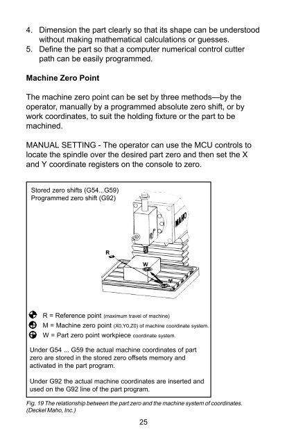
Stored zero shifts (G54...G59)<br />
Programmed zero shift (G92)<br />
R = Reference point (maximum travel of machine)<br />
M = Machine zero point (X0,Y0,Z0) of machine coordinate system.<br />
W = Part zero point workpiece coordinate system.<br />
Under G54 ... G59 the actual machine coordinates of part<br />
zero are stored in the stored zero offsets memory and<br />
activated in the part program.<br />
Under G92 the actual machine coordinates are inserted and<br />
used on the G92 line of the part program.<br />
Fig. 19 The relationship between the part zero and the machine system of coordinates.<br />
(Deckel Maho, Inc.)<br />
25