
You also want an ePaper? Increase the reach of your titles
YUMPU automatically turns print PDFs into web optimized ePapers that Google loves.
ORIGINATION OF FIRE<br />
Engine fires in general<br />
SECTION 9. CAUSES OF FIRE<br />
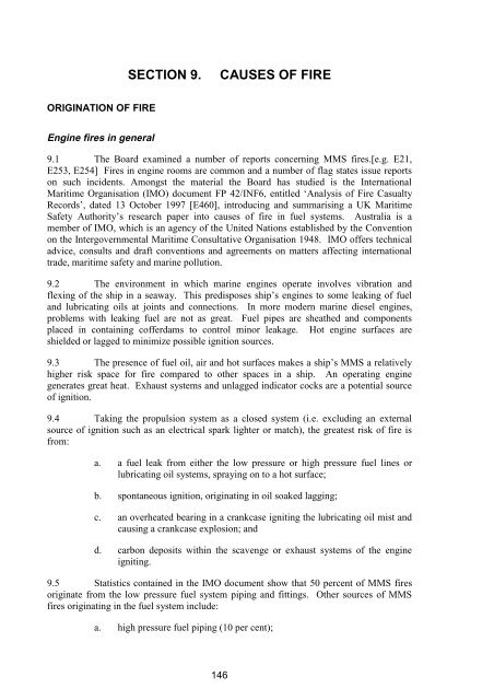
9.1 The Board examined a number of reports concerning MMS fires.[e.g. E21,<br />
E253, E254] Fires in engine rooms are common and a number of flag states issue reports<br />
on such incidents. Amongst the material the Board has studied is the International<br />
Maritime Organisation (IMO) document FP 42/INF6, entitled ‘Analysis of Fire Casualty<br />
Records’, dated 13 October 1997 [E460], introducing and summarising a UK Maritime<br />
Safety Authority’s research paper into causes of fire in fuel systems. Australia is a<br />
member of IMO, which is an agency of the United Nations established by the Convention<br />
on the Intergovernmental Maritime Consultative Organisation 1948. IMO offers technical<br />
advice, consults and draft conventions and agreements on matters affecting international<br />
trade, maritime safety and marine pollution.<br />
9.2 The environment in which marine engines operate involves vibration and<br />
flexing of the ship in a seaway. This predisposes ship’s engines to some leaking of fuel<br />
and lubricating oils at joints and connections. In more modern marine diesel engines,<br />
problems with leaking fuel are not as great. Fuel pipes are sheathed and components<br />
placed in containing cofferdams to control minor leakage. Hot engine surfaces are<br />
shielded or lagged to minimize possible ignition sources.<br />
9.3 The presence of fuel oil, air and hot surfaces makes a ship’s MMS a relatively<br />
higher risk space for fire compared to other spaces in a ship. An operating engine<br />
generates great heat. Exhaust systems and unlagged indicator cocks are a potential source<br />
of ignition.<br />
9.4 Taking the propulsion system as a closed system (i.e. excluding an external<br />
source of ignition such as an electrical spark lighter or match), the greatest risk of fire is<br />
from:<br />
a. a fuel leak from either the low pressure or high pressure fuel lines or<br />
lubricating oil systems, spraying on to a hot surface;<br />
b. spontaneous ignition, originating in oil soaked lagging;<br />
c. an overheated bearing in a crankcase igniting the lubricating oil mist and<br />
causing a crankcase explosion; and<br />
d. carbon deposits within the scavenge or exhaust systems of the engine<br />
igniting.<br />
9.5 Statistics contained in the IMO document show that 50 percent of MMS fires<br />
originate from the low pressure fuel system piping and fittings. Other sources of MMS<br />
fires originating in the fuel system include:<br />
a. high pressure fuel piping (10 per cent);<br />
146
CAUSES OF FIRE<br />
b. slack, fractured or removed studs/bolts (7 per cent);<br />
c. loose/unscrewed or fractured bleed cocks, screws or valves (7 per cent);<br />
and<br />
d. miscellaneous/undetermined fuel leaks (7 per cent).<br />
Ignition point and fuel source<br />
9.6 Detective Senior Constable WA Hawes is a member of the WA Police Arson<br />
Squad. He was part of a Disaster Victim Identification Team comprising officers from the<br />
Emergency Operation Unit, the Forensic Division and the Arson Squad which attended<br />
WESTRALIA at about 1830 on 5 May 1998. The team acted on behalf of the WA State<br />
Coroner and at the invitation of the Navy.<br />
9.7 Detective Senior Constable Hawes expressed the opinion in his Preliminary<br />
Report dated 14 May 1998:-<br />
The most probable explanation from the fire scene examination, is that diesel<br />
fuel has sprayed from the braided fuel line at unit 9, starboard engine onto<br />
hot engine parts. The diesel vapour has been heated to ignition temperature<br />
by this contact, self igniting and sustaining combustion.[E32]<br />
9.8 He explained in his evidence on 15 May 1998 why he termed his report<br />
‘preliminary’:<br />
With fire scene examination, this examination is one part of it. We develop<br />
theories as a result of our examination. These theories we test. A lot of that<br />
testing comes from witnesses, on their observations. At this stage, I haven’t<br />
been able to speak with all witnesses, so therefore all the information is not<br />
available to me.[T305-306]<br />
9.9 Detective Senior Constable Hawes adhered to his original hypothesis when he<br />
was recalled to give further evidence on 27 June 1998 and in his final report dated 15 July<br />
1998.[E452] When he gave further evidence he had had the opportunity to review the<br />
evidence of the witnesses who saw the start of the fire, namely, PO Hollis, PO Francis,<br />
LSMT Smith and LEUT Walters.[T2757] The evidence of the eyewitnesses made it clear<br />
that the fire started on the starboard main engine.[T583, T1242-3, T1459, T1806, T2802]<br />
That evidence, as well as scientific testing, confirmed Detective Senior Constable Hawes<br />
conclusions part of which he stated in his Preliminary Report as follows:<br />
HMAS ‘Westralia’ has suffered a major diesel leak on the inboard side of<br />
the port engine. This diesel has sprayed downwards 45 degrees towards the<br />
starboard engine, and created a diesel vapour cloud above the engines.<br />
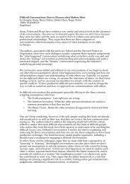
Another diesel leak has occurred in the braided fuel line at unit 9 of the<br />
starboard engine. This has possibly sprayed upwards and outward due to the<br />
inner lining being exposed through the braided outer shell in a cone like<br />
shape.[T310] (Figure 10)<br />
147
CAUSES OF FIRE<br />
Figure 10. Hose S9R. The inner teflon tube can be seen protruding through the<br />
wire braid in a fan shape. (Fig 48 of Metlabs report)<br />
Failure of PME supply hose (No. 8 cylinder) and SME return hose (No. 9<br />
cylinder)<br />
9.10 Detective Senior Constable Hawes made observations of, and with the<br />
assistance of WO Bottomley removed, certain flexible fuel hoses, as described in his<br />
report.[E452] The hoses were later more particularly identified and scientifically<br />
examined by Mr John Bromley, metallurgist (from AMEC Pty Ltd trading as Metlabs).<br />
Evidence before the Board disclosed that on 5 May 1998 two flexible fuel hoses had failed<br />
- namely, a supply hose on the PME, number 8 cylinder (P8S), and a return hose on the<br />
SME, number 9 cylinder (S9R). The second flexible fuel hose appeared to be the primary<br />
cause of the fire as the burst hose provided a source of atomised diesel fuel in the area<br />
where the fire was observed to start. A hot engine part nearby, probably an indicator cock,<br />
provided the source of ignition.[E452, T308-310; E227, T3419, T3546, T4073-4075,<br />
T4180]<br />
Secondary bilge fire and areas of fire damage<br />
9.11 There was evidence of a secondary fire in the bilge. This fire seemed to be<br />
confined outboard of the starboard engine, between frames 30 and 31, 7.650 m and 8.500<br />
m aft of the lower bulkhead of the after pump room.[E452] At bottom plates level, there<br />
was little damage to the polycarbonate light fittings, other than one immediately outboard<br />
and one forward of the apparent seat of the fire. The evidence is that at the bottom plates<br />
level, other than the area outboard of no. 9 cylinder, the temperature was relatively low,<br />
even during the most intense phase of the fire.<br />
9.12 Above this level, at the middle and top plates, more extensive damage could be<br />
seen. Light fittings had melted and heat damage involving the buckling of walkway plates<br />
148
CAUSES OF FIRE<br />
and the melting of alloy sheets forming the backs of ladders. This damage indicated<br />
temperatures in excess of 600°C. The most extensive area of damage was on the underside<br />
of the MCR. All the cabling insulation had been destroyed. Substantial ‘I’ beams for the<br />
MMS hoist had been buckled.<br />
Other expert opinion<br />
9.13 Dr G Goodwin, a Senior Research scientist and engineer with the Defence<br />
Science and Technology Organisation, Maritime Platforms Division and Mr T P Casey,<br />
consulting scientist and engineer, also agreed with Detective Senior Constable Hawes’<br />
hypothesis.[E214 para 38, E228].<br />
9.14 Mr G M Kelly, a fire investigator, was somewhat equivocal: in his opinion<br />
there was ignition by an unidentified source of flammable liquid vapour originating from a<br />
diesel leak(s) from an unidentified source.[E227]<br />
9.15 Mr P E Burge, a marine engineer, whilst canvassing other possible ways in<br />
which the fire may have started, accepted that the most probable cause was that the fire<br />
started with the bursting of the starboard no. 9 cylinder return hose (S9R), the spraying of<br />
fuel onto a heat source and igniting, as described by Detective Senior Constable Hawes in<br />
his Preliminary Report.[E224 para 13.1, T4077-4087]<br />
9.16 Mr Burge ultimately advanced two possible alternative causes of the fire:-<br />
The vapour cloud from the port engine may have been drawn into the turbo<br />
charger of the starboard main engine where it ignited and thus internal fire<br />
melted the aluminium scavenge ducting. The heat in the duct may have<br />
affected the hose immediately beneath it and weakened the hose structure<br />
sufficiently to cause a rupture. Fuel under pressure would then have sprayed<br />
vertically into the hot parts of the duct and also ignited.[E224 para 13.2]<br />
The oily mist atmosphere within the crankcase may have been ignited from<br />
an internal heat source and been released into the engine room. This heat<br />
could have ignited any loose fuel or fuel vapour in its vicinity.[E224 para<br />
13.4]<br />
9.17 In his evidence before the Board, as to the first of those possible alternative<br />
causes of the fire, Mr Burge accepted this as being no more than a possibility [T4083-4]<br />
Mr Bromley conducted a metallurgical assessment of the scavenge ducting (also known as<br />
a charge air rail or inlet manifold) and concluded that the source of the fire where the<br />
ducting had melted adjacent to starboard 9 cylinder was external.[E398] There was no sign<br />
of a fire having occurred internally or of an explosion. Even if an explosive mixture had<br />
been drawn into the scavenge ducting there was no material within the scavenge ducting to<br />
sustain the fire to raise the aluminium to melting temperature.<br />
9.18 Similarly, Mr Burge did not press the second alternative as anything more than<br />
a possibility because of the fact that there was a Gravenor alarm which should have gone<br />
off had there been a crankcase explosion, but did not; that there were signs only of a small<br />
amount of oil leaving the engine (and these signs may have preceded 5 May 1998); and<br />
that there were probably flame traps behind the crankcase doors.[T4086] CMDR Irwin (an<br />
engineer) advised the Board:-<br />
149
Fuel specification<br />
CAUSES OF FIRE<br />
I even question whether there was an explosion at all but rather a raise in air<br />
pressure inside the crankcase caused by the heat.[T3495]<br />
9.19 Analysis of the fuel oil showed that its closed cup flash point was 71°C and<br />
auto ignition temperature was about 310°C.[E311] The fuel was within specification and<br />
there was nothing inherent in it which lead to it being a greater hazard than the engine<br />
design allowed for.<br />
Ignition source<br />
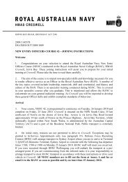
9.20 A probable source of ignition was the adjacent indicator cock (Figure 11). The<br />
indicator cock was not lagged or shielded and could reach temperatures in excess of 450 ο C,<br />
well in excess of the 310°C auto ignition temperature established in testing the fuel sample.<br />
Figure 11. A view of the fire damage to the outboard side of the SME showing<br />
the indicator cocks at cylinders 8, 9 & 10. (Mr G. Kelly)<br />
Fuel supply<br />
9.21 The fuel to the burst return line on the SME was initially supplied under<br />
pressure from the fuel boost pump via the injector pump chambers linking the supply and<br />
return ports. The prompt shut down of the engine isolated this source but the design of the<br />
system is such that fuel can be supplied under pressure due to gravity from the service tank<br />
by means of the return line. The incorrectly fitted and defective back pressure valves<br />
would have presented no barrier to the fuel flow.[E480] The service tank was isolated by<br />
the EOOW at some time between 1048 and 1053.[E91, p10 & p12] Some fuel may have<br />
continued to flow, albeit at a greatly reduced rate, as the fuel lines from the service tank<br />
drained. This final phase of the fuel supply to the fire was not tested.<br />
150
CAUSES OF FIRE<br />
9.22 Examination of WESTRALIA’s liquid cargo chits[E80] gives no indication of<br />
the fuel oil that may have been consumed by the fire. The dips taken on 14 May 1998<br />
show marginally more fuel onboard than on 5 May 1998, although no fuel oil was later<br />
taken onboard in the intervening period.<br />
Conclusion<br />
9.23 The Board accepts the hypothesis of Detective Senior Constable Hawes as<br />
to the start of the fire and finds that the fire started as a result of the ignition of<br />
atomised fuel from a leak in the new flexible return hose on no. 9 cylinder on the<br />
starboard main engine (S9R). The Board finds that the possibility of some other<br />
source of the fire is not sustained by the evidence. The source of the ignition was<br />
probably the adjacent indicator cock on no. 9 cylinder. It seems that fuel may have<br />
continued to supply the fire for at least 15 minutes at a diminishing, and relatively<br />
small, rate.<br />
FAILURE OF THE FLEXIBLE FUEL HOSES<br />
Description of the hoses<br />
9.24 The flexible fuel hoses were made from lengths of a hose which comprised a<br />
teflon inner tube covered by a stainless steel wire braiding containing seven wires or<br />
strands per braid. Fittings were attached at the end of the hoses.<br />
9.25 The supply hoses and return hoses had an exposed hose length of around<br />
140mm and around 160mm respectively. According to a product sheet (which was not<br />
given to ADI or Navy) the hose had, amongst others, the following specifications [E197<br />
Tab 4]:<br />
Diameter of Bore ¾ inches 19mm<br />
Working Pressure 800psi 5.5MPa<br />
Minimum Burst Pressure 3500psi 24.1MPa<br />
Minimum Bend Radius 9 inches 229mm<br />
Hours of operation of the flexible fuel hoses<br />
9.26 WO Bottomley, stated that he believed that although the flexible fuel hoses<br />
were installed on 10 April 1998, the main engines were not operational until 22 April<br />
1998.[E209] The daily TM 136 logs for the period 21 April - 5 May 1998 indicate that the<br />
SME had operated for approximately 39.5 hours, and the PME for approximately 36 hours,<br />
from the time of hose installation to the time of the fire.[E209, T3418-9]<br />
Metallurgical testing of flexible fuel hoses<br />
9.27 The flexible fuel hoses were all removed from WESTRALIA’s engine for<br />
testing in the course of this Inquiry. Mr Bromley, was appointed by the Board to<br />
independently conduct an analysis of the integrity of the hoses.[E194A]<br />
151
CAUSES OF FIRE<br />
Failure of flexible fuel hoses due to fatigue<br />
9.28 Mr Bromley confirmed that all the hoses, with the exception of two, showed<br />
random, isolated fatigue features of several wires. In particular, he confirmed that:<br />
…the two hoses which failed, the supply hose on port 8 cylinder (P8S) and<br />
the return hose on starboard 9 cylinder (S9R), had ruptured as a result of<br />
internal pressurisation due to the fact that approximately 50 adjacent wires in<br />
5 to 7 braids had fractured as a result of prior fatigue cracking, leaving the<br />
internal teflon tube unsupported and hence unable to support the normal<br />
working pressure.[E194A p24]<br />
9.29 Another hose, P12R, was found on examination to have hose characteristics<br />
and a wire fracture disposition similar to P8S and S9R.<br />
9.30 Mr Bromley stated in his report that the production of fatigue cracking in the<br />
wires in the hose would require prolonged exposure to an alternating stress, which in the<br />
hoses would be consistent with a variable pressure induced by the (fuel) injector pump.<br />
Further, the damage in the three hoses in which adjacent braids were fractured suggested<br />
that these hoses were subjected to more severe fatigue conditions either due to an increase<br />
in internal pulsating pressure or an increased stress concentration produced as a result of<br />
more radical mechanical damage sustained in prior use.[E194A p25]<br />
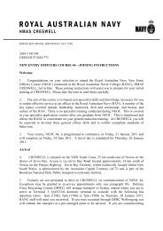
Figure 12. The SEM photo of the fracture surface of the wires from the used fuel<br />
line, identified as: P5R 491/16, which was burst in testing, showed the<br />
fatigue markings present on smooth flat fracture face and the absence<br />
of any bulk thinning (scale - 100 microns). (Fig 32 Metlabs report)<br />
152
CAUSES OF FIRE<br />
9.31 Compare figure 12 above, which shows a classic fatigue failure, with the<br />
following photograph (Figure 13), which shows a pressurisation rupture, induced by<br />
hydro-testing to failure. The wedge shaped fracture surfaces in several wires are<br />
associated with tensile failure.<br />
Figure 13. The SEM photo of the fracture surface of the wires from the used fuel<br />
line, identified as: P5R 491/16, which was burst in testing, showed a<br />
necked, wedge shaped fracture on the wires at the rupture (scale =<br />
100 microns). (Fig 33 Metlabs report)<br />
9.32 The results indicating that the hoses failed due to fatigue are not controverted<br />
and are basically accepted by the other experts.[Goodwin E214 para 43; Burge E224 para<br />
16.2; and Casey E228 para 6.5]<br />
Conclusion<br />
9.33 Flexible fuel hoses S9R and P8S failed by reason of fatigue of the stainless<br />
steel braiding.<br />
Other testing results<br />
9.34 Selected hoses were pressure-tested to destruction. Only one, P12R (noted<br />
above as a hose with characteristics and a wire fracture disposition similar to P8S and S9R)<br />
failed at less than the manufacturer’s stipulated burst pressure.[E194 para 11] Mr Bromley<br />
also concluded that hoses P8S and S9R would have ruptured at less than expected<br />
pressure.[E194 para 24]<br />
153
CAUSES OF FIRE<br />
9.35 On examination, there were signs of mechanical damage to many hoses,<br />
particularly permanent sets and internal creases. These were found not to significantly<br />
affect the static burst strength.[E194 pp8 and 25]<br />
9.36 In order to test the possibility that damage sustained during installation and/or<br />
reinstallation contributed to the failure of the flexible fuel hoses, a sample hose, identified<br />
as ‘D’, was gripped using a pair of multigrips and severely twisted and bent in order to<br />
produce major damage. Extensive internal and external deformation occurred with the<br />
production of scoring and denting but only one obvious fracture of a wire.[E194 para 3.13]<br />
Hose D was then pressure tested and failed at just under the minimum specified burst<br />
pressure.[E194 para 4.1.3] This testing was video-recorded and shown to the intervening<br />
parties.<br />
Figure 14. The recently assembled unused fuel line, identified as D, was<br />
extensively twisted and bent, producing permanent distortion,<br />
abrasion and a broken strand. (Fig 26 Metlabs report)<br />
Conclusion<br />
9.37 The Board is satisfied that the results of the metallurgical testing indicate<br />
that any mishandling, if it occurred during or after initial installation, did not<br />
contribute in any significant way to a major reduction in the burst strength of the<br />
hoses.<br />
Spill pulse pressure<br />
9.38 What caused the flexible fuel hoses to fatigue? Dr Goodwin is regarded as<br />
DSTO’s resident consultant on diesel engine matters. Dr Goodwin was of the opinion that<br />
the only likely cause of fatigue failure in the flexible fuel hoses was pressure pulsation<br />
originating at the fill and spill ports of the injector pumps.[E214 para 41] Mr Burge was in<br />
154
CAUSES OF FIRE<br />
agreement with Dr Goodwin as to the phenomenon of fuel pump ‘feedback’ pressure<br />
pulses (as he referred to them) and which he further described in his report as follows:-<br />
In WESTRALIA’s engines, the sharp release of fuel oil under high pressure<br />
from the fuel pump plunger through the spill orifice (port) into the annular<br />
groove which is machined into the pump body and which forms the common<br />
fuel inlet/return gallery, results in pressure shock pulses which are felt in<br />
both the fuel supply and return systems.[E224 para 7.1]<br />
9.39 The magnitude of the peak value of these pulses would be at least of an order<br />
of magnitude greater than the background pressure of the system but of unknown<br />
limits.[T3508-3520, E214D, E401(ER401 para 7.6), T4135-9]. Mr Burge pointed out in<br />
his report:-<br />
The British MSA Research Paper 401 in Clause 8.1.5 indicates that the peak<br />
pressures of the ‘feedback’ pulses within a fuel reticulation system could<br />
range between 41 Bar and 80 Bar and that the pulses are less significant if<br />
the light MDO is used rather than HFO. WESTRALIA uses MDO. In this<br />
letter dates 20 May 1998 the manufacturers agents, Rolls-Royce, have<br />
suggested that the magnitude of the pulses could be as low as 30 Bar (435.1<br />
psi or 3,000kPa) and as high as 70 Bar (7000 kPa or 1015.30 psi). I have not<br />
been able to find a definitive industry statement about ‘feedback’<br />
pulses.[E224 para 7.6]<br />
9.40 The magnitude of the pulses would affect the minimum acceptable burst<br />
pressure and the frequency of the pulses would need to be considered for its effect on the<br />
fatigue life of the pipes and, for example, a letter from Rolls Royce dated 15 May 1998,<br />
states at paragraph 3:<br />
The design of all supply pipework and the associated fitting must recognise<br />
the above service conditions. The design criteria has to encompass<br />
appropriate margins for both the peak pressure and the potential fatigue<br />
aspects arising from the high frequency of the applied pressure pulses. The<br />
design as originally supplied fulfilled the above requirements.[E181]<br />
9.41 Dr Goodwin was of the opinion that the hoses had been selected with a safe<br />
margin over the background pressure, but that the evidence indicated that no consideration<br />
had been given to the pressure pulses.<br />
Number of pulses<br />
9.42 According to the expert evidence provided to the Board, 1 million stress<br />
reversals or pulses could bring about the fatigue fractures evidenced on the braid of the<br />
hoses.[Bromley T3252, Goodwin T3514]<br />
9.43 The two Pielstick PC2.2 engines in WESTRALIA:<br />
a. have 14 cylinders (7 cylinders in each bank);<br />
b. operate at a constant 500 revolutions per minute; and<br />
c. each cylinder fires once every two revolutions.[T3513-5]<br />
155
CAUSES OF FIRE<br />
9.44 By way of illustration, a simplified way to estimate the likely frequency of the<br />
pulse for the whole engine, ignoring pulse reflections, can be calculated as follows:<br />
Number of cylinders × Revs per second<br />
Pulses per sec =<br />
Rate of cylinder firing<br />
14 × 8.33<br />
=<br />
2<br />
= 58 pulses/sec [407]<br />
9.45 Although not definitive, this calculation suggests that the flexible fuel hoses<br />
were coping with a potential 58 pulses per second. On this basis, WESTRALIA’s engines<br />
would have had to operate only for a short amount of time, in the order of 4.76 hours, to<br />
reach 1 million pulses.<br />
Conclusion<br />
9.46 Sufficient pressure pulses to cause fatigue failure of the braiding could<br />
easily have been generated since installation of the flexible fuel hoses.<br />
Pielstick, IMO and other information relating to ‘spill pulse’<br />
9.47 The Board received evidence that from the early 1970s, the ‘spill pulse’<br />
phenomenon had been known to the manufacturers of Pielstick engines, their licensees and<br />
others in the marine diesel industry.[E214D, T4141] Any modification of the fuel delivery<br />
system needed to encompass appropriate margins for both peak pressures and potential<br />
fatigue aspects arising from the high frequency of the applied pressure pulses.[E181]<br />
Pielstick Service Bulletins<br />
9.48 In Service Bulletins which it issued, Pielstick engine agents, NEI Crossley<br />
Engines (now part of Rolls Royce PLC) identified a high spill pulse or pulse spiking as a<br />
feature of the Pielstick engines, or more particularly, the jerk injection fuel pump system<br />
incorporated with the engine.[E189]<br />
Pielstick Service Bulletin 51 [E189]<br />
9.49 On the subject of fuel pump isolation cocks in PC2.2 and PC2.3 engines,<br />
Pielstick Service Bulletin 51 was issued on 2 September 1991. The last paragraph of page<br />
one of the bulletin states as follows:<br />
On all these cocks there has been leakage due to incorrect fitting of the ‘O’<br />
rings. It was therefore replaced by a ball valve (PC16677) Fig IV. This<br />
valve has been satisfactory in most installations, but with certain fuels the<br />
pulsating load [emphasis added] in the fuel main has caused failure of the<br />
seats.<br />
9.50 Page 2 of the Bulletin introduced a new cock (PC196818) for use on all<br />
engines from serial number18152 onwards and warned:<br />
It is vitally important that the valve is screwed firmly on to the lower set<br />
when closed and on to the upper seat when open. In other words, the valve<br />
must not be left in an intermediate position, where the high pressure pulses<br />
156
CAUSES OF FIRE<br />
[emphasis added] from the fuel injection pump will damage the seats. In<br />
either direction, opening or closing, the valve spindle must be turned until<br />
resistance is felt, indicating contact with the seat and must not be backed-off.<br />
9.51 Clearly printed along the side and across the bottom of each page of each<br />
Pielstick Service Bulletin (including each page of bulletins 51 and 78) is the phrase, ‘This<br />
data is important to service engineers, operators and maintenance staff’.<br />
Pielstick Service Bulletin 78 [E58 Tab 7, E189]<br />
9.52 Pielstick Service Bulletin 78 also dated 2 September 1991 advised that<br />
Pielstick had developed a system whereby flexible fuel hoses could be fitted to the engines.<br />
However, the flexible fuel hoses were part of a general package of modifications which<br />
took into account the spill pulse phenomenon. Pielstick Service Bulletin 78 stated that the<br />
engine makers should be contacted for details and advised of the availability of pulsation<br />
dampers which ‘reduce the spill pulse to an acceptable level’.[E58 Tab 7]<br />
Criticism of Pielstick Service Bulletins<br />
9.53 Criticism was made of the sufficiency of the references to spill phenomenon in<br />
these Bulletins in the closing addresses on behalf of ADI [T4359] and Parker Enzed<br />
Technology [T4434] In his evidence, Dr Goodwin conceded that it would have been<br />
appropriate for the Bulletins to have included a warning about the phenomenon.[T3538]<br />
9.54 As will be developed in <strong>Section</strong> 10 of this Report, neither ADI (nor the other<br />
intervening parties) nor for that matter, the Navy gave any consideration to the Bulletins,<br />
let alone enquired of the engine agents concerning it. The appropriateness of enquiry of<br />
the engine agent’s was emphasised by Dr Goodwin:-<br />
Conclusion<br />
…I just wonder if, in your opinion, a professional engineer had been asked<br />
to comment on a proposal to change from rigid fuel hoses to flexible fuel<br />
hoses in a particular type of engine, he might have actually seriously<br />
considered ringing the engine manufacturer to get some advice?<br />
…Absolutely. I think the first thing I’d have done is to delve into literature<br />
and go for a library search and probably on the second day I’d have thought,<br />
‘Why don’t I ask the manufacturer?’ I think an engineer who was more<br />
inclined to be doing this work on a routine basis as modification, I think he’d<br />
have run to the manufacturer first.[T3575-3576]<br />
9.55 Regardless of the quality of the information contained in the Pielstick<br />
Service Bulletins, information on the subject of spill pulses was available from the<br />
Pielstick engine agents, NEI Crossley Engines, at the time of AMP 12. Even a cursory<br />
examination of the Bulletins should have alerted a reasonably competent engineer to<br />
the existence of the spill pulse phenomenon and should have aroused sufficient<br />
curiousity in any technical person to make further enquiry. A reasonably competent<br />
engineer would have given the phenomenon due consideration and would have<br />
communicated with the engine agents. Indeed, any technical person who was charged<br />
with having the flexible fuel hoses manufactured and installed should have<br />
communicated with the engine agents.<br />
157
CAUSES OF FIRE<br />
International Maritime Organization (IMO) documentation<br />
9.56 The issue of shipping industry awareness of the effect of spill pulses is also<br />
supported by the content of documentation issued by the International Maritime<br />
Organization (IMO).<br />
IMO Paper 1994<br />
9.57 IMO Marine Safety Committee Circular (MSC Circ.647) entitled, ‘Guidelines<br />
to Minimize Leakages from Flammable Liquid Systems’ was issued on 6 June<br />
1994.[E462] In relation to the design and construction of hose and hose assemblies MSC<br />
Circ. 647 states as follows:<br />
IMO paper 1997<br />
Hoses should be constructed to a recognized standard and be approved as<br />
suitable for the intended service, taking into account pressure, temperature,<br />
fluid compatibility and mechanical loading including impulse (emphasis<br />
added) where applicable.[Appendix 2, p 5, para 3]<br />
9.58 The UK MSA research paper of January 1997 referred to in the IMO paper<br />
reference FP42/AMF6 dated 13 October 1997 dealt extensively with the phenomenon.<br />
Paragraph 8 of the IMO paper stated:-<br />
Conclusion<br />
High pressure pulses lead to vibration and fatigue…The failure of fuel lines<br />
and their components will invariably involve fatigue and the initiation of<br />
fractures due to tensile stress.[E460]<br />
9.59 The Board is of the view that information concerning the spill pulse<br />
phenomena was available and accessible had it been sought. It was not sought.<br />
Awareness of spill pulse by sea-going engineers<br />
9.60 Dr Goodwin attended a meeting on 3 July 1998 held at Wartsila-NSD Australia<br />
(Wartsila) in Sydney, where, amongst other things, awareness of spill pulse was<br />
discussed.[E401, T4141] Dr Goodwin stated in evidence that at this meeting:-<br />
…there was a general consensus that the industry normally deals with these<br />
pulses, and not knowing their magnitude, by simply over-engineering and<br />
using much, much stronger pipes than you would need to use for the nominal<br />
set pressure. And it became clear to us, I think, that several of the people<br />
there thought that everyone ought to be aware of these pulses…[T4141]<br />
9.61 Dr Goodwin gave evidence that on 7 July 1998 he telephoned Mr Eric Clarke,<br />
General Manager, Wartsila, with a view to confirming whether their knowledge of spill<br />
pulse arose as a result of their marine engineering training or the work experience they had<br />
in recent years. Mr Clarke told him that he was trained in England about 24 years ago. He<br />
assured Dr Goodwin that a full description of the fuel systems of diesel engines was<br />
explained in those courses and that he was made aware of the characteristics of jerk pumps<br />
and the sort of signals they produced. Mr Clarke expressed the opinion, that anyone who<br />
had completed the kind of course he had, would be similarly aware.[T4141-2] He also<br />
158
CAUSES OF FIRE<br />
spoke to Mr Jeff Cleary, Wartsila’s Service Engineer, who had previously spent 9 years<br />
teaching marine engineering at Sydney Institute of Technology. According to Dr<br />
Goodwin, Mr Clarke told him that in his opinion:-<br />
…anybody who had a Dip. Marine, an advanced Dip. Marine or a first-class<br />
marine engineering certificate involving engines – that is the motor part of<br />
those qualifications – should be well aware of the effect of spill<br />
pulses.[T4142]<br />
9.62 As a result of these discussions, Dr Goodwin stated that:-<br />
Last week I was prepared to say it was clearly well-known in the engine<br />
industry, but this evidence seems to me to show it’s well-known amongst<br />
sea-going engineers in the merchant navy . . . Navy maintainers, at least now<br />
in some arms of the Fleet, are not being trained for heavy maintenance work<br />
and they probably would have to have the kind of training that a sea-going<br />
chief engineer in the merchant navy would have. Given also that Navy<br />
training is also done by senior sailors and engineering officers who’ve come<br />
through the Navy training system themselves, I suspect there may be a<br />
serious gap in Navy training in this area and that’s why I think the Naval<br />
staff may be unaware of things that the merchant marine sea-going engineers<br />
should be aware of.[T4143]<br />
9.63 Mr Burge’s evidence was that his inquiries indicated, amongst other things,<br />
that the effect of spill pulses was not well known and in particular it was not taught in the<br />
marine engineering school at the Marine Centre South Fremantle TAFE College.[T4372]<br />
Conclusion<br />
9.64 Marine engineers with qualifications acceptable to the Merchant Navy<br />
would probably have been aware of the nature of pulses caused by jerk pumps, if not<br />
the full extent of spill pulse pressure.<br />
9.65 Neither Dr Goodwin nor Mr Burge have relevant expertise on the subject<br />
of RAN marine engineering training. The purpose of RAN marine engineering<br />
training is not to develop expertise in all aspects of engineering design but is more<br />
targeted at machinery operation, accordingly, knowledge of ‘spill pulses’ is not an<br />
essential training requirement. Appropriate experts in industry are usually used for<br />
deep specialist skills.<br />
Outstanding issues between experts<br />
9.66 The Board has been significantly assisted by the evidence of Dr Goodwin and<br />
Mr Burge. By the end of the hearing, Dr Goodwin and Mr Burge were in substantial<br />
agreement, with the exception of two issues:<br />
a. the possibility of relevant over pressure in the fuel hoses occurring as the<br />
result of some malfunction in the fuel system [E224 paras 14-15]; and<br />
b. the extent of knowledge of the spill or feedback pressure in diesel fuel<br />
hoses from high pressure fuel pumps.<br />
The second of these issues has already been addressed above.<br />
159
CAUSES OF FIRE<br />
Overpressure occurring due to fuel system malfunction<br />
9.67 ADI suggested that the hose ruptures may have been caused prematurely by a<br />
pressure surge operating on degraded hoses. This surge was indicated by defects on three<br />
fuel system pressure gauges.[T517, T4385]<br />
9.68 Dr Goodwin viewed the gauges as photographs and gave evidence on the<br />
issue.[E135, T3516-3120 and 3567-3570] In commenting on Mr Casey’s report [E228 in<br />
E401-ER031], Dr Goodwin stated that he was not convinced that any of these (fuel<br />
gauges) related to real overpressures and that one had failed by partial vacuum. Dr<br />
Goodwin did not place much credence in the evidence of the gauges. He stated that the<br />
MCR repeater was reading an electrical signal from a pressure transmitter near the fire and<br />
that this was far more likely to be an artefact of a measuring system in an overheated state.<br />
Dr Goodwin concluded that even if there was a real overpressure, it may have been by<br />
overheating of a ‘dead leg’ of pipework attached to the gauge during the fire.<br />
9.69 Whilst the failed gauges do not feature as such in Mr Burge’s conclusions,<br />
those conclusions in paragraph 16.3 refer to ‘excessive surge pressure’ and include these<br />
two paragraphs:<br />
16.4 There is insufficient data to determine the characteristics of the forces<br />
which had caused the fatigue failure in the ruptured flexible hoses. A range<br />
of engineering analyses and tests needs to be conducted to establish the<br />
precise nature and extent of these forces.<br />
16.6 To the extent that aspects of this report are inconclusive, it is because<br />
of a lack of data available about the status of elements in WESTRALIA’s<br />
engine operating systems.[E224]<br />
9.70 Mr Burge’s attention was drawn to Dr Goodwin’s evidence on the failed<br />
gauges during his oral evidence. Mr Burge spoke of gauges ‘wildly fluctuating’ but<br />
accepted the possibility of the damage to the gauges occurring after the fire.[T4104-4106]<br />
9.71 In a letter to the Board, from ADI’s solicitors it was submitted:<br />
What is clear from the Metlab’s report is that fatigue damage to 53 fuel<br />
supply and return hoses did not render the hoses unfit for their purpose and<br />
they continued to function entirely satisfactorily up to the point where the<br />
main engines were declutched. Three of the hoses examined showed<br />
evidence of degradation which was sufficiently severe as to expose the hoses<br />
to the risk of rupture when subjected to abnormal pressure. The degradation<br />
was caused either by localised abnormal pulse pressure or mechanical<br />
damage. But for the abnormal pulse pressure or the mechanical damage it is<br />
highly probable that the hoses would not have failed and would have<br />
remained fit for their purpose at all material times.[E214E]<br />
9.72 Dr Goodwin was asked to comment on the ADI assertions.[T3521-3522] He<br />
replied as follows:<br />
The first sentence says that the fatigue damage to 53 hoses didn’t render the<br />
hoses unfit for purpose. I’m not sure what the meaning of that. There were<br />
56 hoses. If any one of them fails a dangerous situation arises. So there was<br />
by reductio ad absurdum; for example, you wouldn’t think an aircraft wing<br />
was strong enough if only one of them fell of and that’s sort of - - that’s an<br />
analogy. I mean, the fact that 53 survived is not really a terribly important<br />
160
CAUSES OF FIRE<br />
issue. The fact that three failed is the important issue, it seems to me. I<br />
think there’s a matter of fact here they can either function up to the point<br />
where the main engines were declutched - - that’s true of the 53, that’s right.<br />
It’s actually true of 54, I think, because the one that failed under test hadn’t<br />
failed at this point. I think where a lack of understanding is really shown<br />
here, in this, with respect - - I think there’s a misunderstanding here. When -<br />
- the second sentence refers to ‘exposing the hoses to risk of rupture when<br />
subjected to abnormal pressure’. I think there’s quite enough evidence before<br />
us to show that the large pressure pulses in the fuel lines of these pumps is<br />
not abnormal pressure. It may be pressure that’s very much higher than the<br />
nominal supply pressure; but the normal pressure for this engine is the<br />
nominal supply pressure plus the pulses that come from these pumps. That<br />
is the normal working pressure. It includes quite large pulses. Those pulses<br />
are part of the normal working pressure, but they don’t show in the nominal<br />
supply pressure. I think that’s an important distinction. So, the pulses are<br />
not abnormal at all. There’s plenty of evidence, I think, before us now that<br />
these pulses are regarded as quite normal in engines of this class. So, the<br />
degradation was caused by local pulses, but they weren’t abnormal pulses, in<br />
my opinion; and it’s possible that mechanical damage - - some of the hoses<br />
may have exacerbated the problem by providing sites for the initiation of<br />
fatigue cracks, but there doesn’t appear to be much of that damage, and there<br />
appear to be a lot of hoses which had a significant number of broken strands<br />
in fatigue where I don’t think there was serious mechanical damage.[T3521-<br />
3523]<br />
9.73 WESTRALIA has two oil fuel boost pumps located at the port side of the<br />
MMS on middle plates. They are mounted side by side, and designated ‘outboard’ and<br />
‘inboard’. The inboard pump is fed from the main switchboard via the starboard group<br />
starter board located in the MCR. The outboard pump has two sources of power. Its<br />
normal source is from the main switchboard via the port group starter board located in the<br />
MCR, while its emergency supply is from the emergency switchboard.[E212p1]<br />
9.74 At the request of the Board of Inquiry, the inboard fuel boost pump that was<br />
running at the time of the fire was removed from WESTRALIA and placed in a Watmarine<br />
Engineering Services (Watmarine) test rig. The fuel discharge pressure from the pumps is<br />
controlled by an integral recirculating valve sometimes known as the relief or control<br />
valve. The purpose of the testing was firstly, to check the setting of the control valve and<br />
hence the likely fuel supply pressure of the time of the fire and secondly, to determine the<br />
maximum pressure the pump could produce. This latter test was to see whether the pump<br />
was capable of producing the full scale deflection of the defective fuel system pressure<br />
gauges.<br />
9.75 Watmarine prepared a pump test certificate dated 29 June 1998 which showed<br />
the pumps performance characteristics.[E212 and T3491]<br />
9.76 In his report, CMDR Irwin commented that in the event of a zero flow (i.e.<br />
point of maximum output pressure for a positive displacement pump) situation, the pump<br />
was shown to relieve internally giving a maximum pressure of 625 kPa. After adjustment,<br />
the maximum output pressure the pump was capable of producing with the bypass closed,<br />
was measured to be 960 kPa.[E212(folio 333 para 3)] This is well below the full scale<br />
deflection of the defective gauges.<br />
161
Conclusion<br />
CAUSES OF FIRE<br />
9.77 The fuel boost pump in use at the time of the fire was set at the correct<br />
pressure and was not capable of producing the full scale deflection pressure indicated<br />
by the defective fuel system gauges.<br />
9.78 Based on the expert evidence presented to the Board and the results of<br />
testing carried out on the fuel boost pump and pressure gauges, the Board prefers Dr<br />
Goodwin’s evidence on the subject of fuel gauges. The Board is satisfied that there is<br />
no evidence of a mechanism which could have produced an abnormal pressure pulse<br />
of sufficient magnitude to cause failure of the flexible fuel hoses.<br />
Other problems with flexible fuel hoses<br />
9.79 Apart from the spill pulse phenomenon, there are a number of other important<br />
design issues which were not considered.<br />
Bend radius<br />
9.80 Dr Goodwin gave evidence of a possible explanation for the signs of physical<br />
damage to many of the hoses.[R9.35] He advised that the bend radius of some of the<br />
return hoses appeared to be too small (ignoring possible additional bending during<br />
installation). In accordance with its product sheet, the minimum allowed bend radius for<br />
SST12 Astraflex hose is 9 inches.[E197 Tab 4]<br />
9.81 During his oral evidence Dr Goodwin stated that he had reviewed the hose’s<br />
bend radius by looking at photographs and taking measurements from a sample hose. Dr<br />
Goodwin stated that he was convinced that the bend radius was about 5.8 inches, which is<br />
substantially less than the minimum specified radius of nine inches. As a result, Dr<br />
Goodwin concluded that the hose was actually bent 25% more tightly in application than<br />
the specification allows.[T3502, T4131] While Dr Goodwin did not suggest that this was a<br />
cause of the fire, he thought it was an indication of inappropriate engineering<br />
design.[T3503] Dr Goodwin concluded that the SST12 hose could not be fitted in this<br />
particular location, to join the two connections points together, and meet its own<br />
specifications. In other words, it exceeded the allowed tightness of the bend.[T3504]<br />
9.82 In its closing address, ADI submitted that Dr Goodwin’s evidence concerning<br />
the alleged failure of the hoses to meet specifications as to the minimum bend radius was<br />
not free from doubt, given that the hose was not measured in situ, but measurements were<br />
taken from a sample hose and working from photographs, as well as his admission that his<br />
measurements were not very precise.[T4370]<br />
Conclusion<br />
9.83 Whilst Dr Goodwin’s measurements are not exact, they provide strong<br />
indications that the minimum hose bend radius requirements were ignored by the<br />
design.<br />
Fitting flexible hoses in a straight line<br />
9.84 Dr Goodwin gave evidence that hoses should not be installed straight.[T3506]<br />
Dr Goodwin based his statement on a text entitled Hose Technology by Colin Evans,<br />
162
CAUSES OF FIRE<br />
published in 1974. The substance of Dr Goodwin’s evidence was that rubber or PTFE has a<br />
very different coefficient of expansion than that of iron or steel components and there<br />
needs to be room for it to move with thermal stress and changes of pressure.<br />
Consequently, if a hose is installed straight, it is likely to be under compression or<br />
tension.[T3506] Some examples of hose installation guidelines are shown in figures<br />
15-17.<br />
9.85 Measurement of the lengths of the hoses demonstrated some variability. In<br />
relation to the impact on the static loading due to different hose lengths, Dr Goodwin and<br />
Mr Bromley commented that if a static load, such as tension or compression, is added to a<br />
fatigue load then the hose loading situation is worsened.[Metlabs Report E194A pp3-7]<br />
Dr Goodwin formed the opinion that a short, straight hose was not a good design solution.<br />
Dr Goodwin also agreed with Mr Bromley that the straight arrangement provided no<br />
accommodation for different lengths of hose or different gaps to be bridged.[T3506]<br />
Mr Burge agreed that a combination of a wide gap and a short hose could put a hose under<br />
tension when the end fittings were tightened. Mr Burge further agreed that these<br />
conditions would have an impact on the loading of the braid and its susceptibility to fatigue<br />
damage.[T4103]<br />
Figure 15. E214C - Fig 34 from Hose Technology by Colin Evans<br />
163
CAUSES OF FIRE<br />
Figure 16. Metallic flexible hose general installation guidelines issued in the<br />
Annex to MSC Circ. 647 - Figure 2.1.<br />
164
CAUSES OF FIRE<br />
Figure 17. Non-metallic flexible hose general installation guidelines issued in the<br />
Annex to MSC Circ. 647 - Figure 2.2.<br />
165
Lack of means of restraint<br />
CAUSES OF FIRE<br />
9.86 There is evidence that the return hoses were longer than the supply hoses, were<br />
curved and all had internal creasing.[T4103, T4131] The supply hoses were the straight<br />
hoses and the majority did not have creasing.[E401, T4131] Having explained how the<br />
return hoses could have been damaged by excessive bending, Dr Goodwin searched for an<br />
explanation of how some of the straight supply hoses could have been damaged resulting<br />
in internal creasing. As there is substantial evidence that the crew took care handling the<br />
hoses, Dr Goodwin thought it unlikely that mishandling was the cause of the creasing in<br />
the supply hoses.[T4132] Dr Goodwin examined the design of the hose coupling.<br />
Figure 18. Diagram by Dr Goodwin explaining potential for hose twisting caused<br />
by design of fitting.<br />
9.87 He observed that as one tightens the union nut, it tends to try to twist the hose<br />
tail. The friction at point ‘A’ in figure 18 is what stops the hose tail from twisting. Dr<br />
Goodwin estimated the torque at ‘A’ to be around 30% higher than the torque at ‘B’, so<br />
tightening the nut should not have the effect of twisting the hose.[T4133]<br />
9.88 Dr Goodwin gave evidence that friction analysis only works if both surfaces<br />
are in the same condition - here the hose is going into a fuel union. He explained, that if<br />
surface ‘A’ is wet with fuel, a type of lubricant, and surface ‘B’ is dry, then it is possible<br />
that the torque at ‘B’ exceeds the torque at ‘A’. As the nut is tightened, the hose tail will<br />
tend to rotate. Dr Goodwin stated that both ends of the hose would have the same problem<br />
and that this is a detail design issue rather than an assembly issue.[T4133, E401-ER032]<br />
166
CAUSES OF FIRE<br />
9.89 Dr Goodwin noted that if it is essential that the hoses are not twisted in<br />
assembly, and a twist of 5 degrees may be sufficient to cause damage, there needs to be<br />
some means of holding the hoses in correct alignment while the unions are tightened, such<br />
as flats on the ferrules so that a second spanner can be used to prevent hose rotation.[E401-<br />
ER032] In Dr Goodwin’s opinion, there is no effective way to restrain the hose from<br />
twisting.[T4133]<br />
9.90 Dr Goodwin concluded that:<br />
General lack of design<br />
a. there was no provision for preventing a twist of the hose as one tightens<br />
the nut; and<br />
b. it was likely that the damaged supply hoses were damaged in twisting<br />
rather than bending.[T4133, E401-ER032]<br />
9.91 Dr Goodwin concluded that no design analysis had been carried out in relation<br />
to the installation of the flexible fuel hoses. Flexible fuel hoses had simply been used to<br />
replace fixed rigid steel lines, without any recognition that this was a design change that<br />
required the attention of a design engineer. Dr Goodwin stated that a design engineer<br />
would have taken into account the pulsation in the system. The failure to take into account<br />
pulsation in the system meant that the flexible fuel hoses were destined to fail eventually<br />
due to fatigue, however well made or fitted.[T4232]<br />
9.92 Dr Goodwin concluded in his report that:<br />
Conclusion<br />
There is convincing evidence that the fuel for the fire was supplied by a<br />
failure in fatigue of a return hose. These hoses were not fit for purpose<br />
because of an aspect of the requirement which was not understood by any of<br />
the parties involved. I would expect an examination of this change as an<br />
engineering design issue to have led to the consideration of the dynamic<br />
nature of the working pressure and therefore to an appreciation of the fatigue<br />
requirement.[E214]<br />
9.93 The hose arrangement did not conform with good engineering practice in<br />
various respects, as well as the failure to take into account spill pulses.<br />
9.94 The flexible fuel hoses were not properly designed and they were destined<br />
to fail.<br />
Design improvements to flexible fuel hose assemblies<br />
9.95 Since the dissemination of MSC Circ.647 in June 1994 [E462], IMO has<br />
prepared draft MSC Circ.861 which was approved in May 1998.[E214F] As at 17 June<br />
1998, it had not yet been issued. MSC Circ.861 was reviewed by the Sub-Committee on<br />
Ship Design and Equipment in March 1998 and was passed to the MSC unchanged.<br />
9.96 Draft MSC Circ. 861 states that there had been a continuing incidence of MMS<br />
fires due to the leakage of oil. Investigation of fire casualties, analysis of casualty statistics<br />
and technical research has revealed that leakages from the fuel system are due to the failure<br />
167
CAUSES OF FIRE<br />
of worn, incorrectly fitted, slack, over-tightened or unsuitable components. IMO found that<br />
the major contributing factors to failure of fuel system components were:<br />
a. the frequent partial dismantling and reassembly of the system for<br />
maintenance purposes;<br />
b. the effects of high frequency, short duration pressure pulses which are<br />
generated by the action of the fuel injection pumps and which are<br />
transmitted back into the fuel supply and spill rails; and<br />
c. vibration.<br />
9.97 In relation to design consideration, draft MSC Circ. 861 states, among others:<br />
Recommendation<br />
3.1 It is essential that the fuel system is designed to accommodate the high<br />
pressure pulses which will be generated by the injection pumps. The engine<br />
manufacturer and/or the fuel installation manufacturer and the piping<br />
installer etc. must be consulted for an explicit statement of the fuel system<br />
parameters, including the maximum pressures which will be generated.<br />
Many engine manufacturers, aware of the potential risks due to high pressure<br />
pulses within the fuel system, now aim to limit the magnitude of the pulses<br />
to 16 bar at the engine fuel rail outlets.<br />
3.2 The alternative approaches which may be considered by the designer<br />
are:<br />
- design of the fuel system such that it is able to contend with the magnitude<br />
of pressure pulses which are generated. Piping systems should be designed<br />
and installed to an appropriate classification society or ISO specification;<br />
- installation of pressure damping devices; or<br />
- specification of injection pumps which are designed to eliminate or reduce<br />
high pressure pulses.’<br />
9.98 The RAN should adopt the guidelines set out in IMO’s draft MSC Circ.<br />
861 in relation to diesel engine fuel systems.<br />
168