short-circuit characteristics of airborne dc and ac generators ...
short-circuit characteristics of airborne dc and ac generators ...
short-circuit characteristics of airborne dc and ac generators ...

Create successful ePaper yourself
Turn your PDF publications into a flip-book with our unique Google optimized e-Paper software.
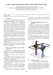
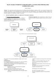
From the equation it follows that the currecnt consists <strong>of</strong> three<br />
components corresponding to the three parts <strong>of</strong> the right side <strong>of</strong> the<br />
equation. The first component is dependable on the generator load<br />
current before <strong>short</strong>-<strong>circuit</strong>, the second component on the remanent<br />
magnetism <strong>and</strong> the third one on the value <strong>of</strong> the current in the<br />
excitation <strong>circuit</strong>. Components behaviour is ilustrated in Fig. 1.<br />
The corresponding computer model <strong>of</strong> DC-generator was assembled<br />
in the Simulink environment using st<strong>and</strong>ard blocks with the<br />
following basic parameters <strong>of</strong> the DC-generator:<br />
P n = 9 kW, U n = 28,5 V, I a = 400A, I b = 6A n = 4500 ot/min, R a =<br />
0,024 Ω, R b = 3,5 Ω, L a = 2,8.10-5 H, L b = 0,1 H , N = 228z, p = 3,<br />
a = 3, c e = 0,00038, U rem = 1,4V.<br />
Ik [A]<br />
800<br />
700<br />
600<br />
500<br />
400<br />
300<br />
200<br />
100<br />
0<br />
0<br />
0.05<br />
cas [s]<br />
0.1 3.5<br />
Ik= fnc(t)<br />
4<br />
Rb [ohm]<br />
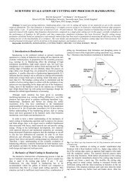
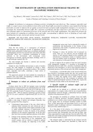
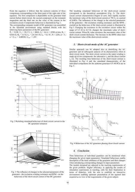
Fig. 2 Resulting simulated behaviour <strong>of</strong> <strong>short</strong>-<strong>circuit</strong> current in the<br />
DC-generator armature<br />
Ik [A]<br />
1200<br />
1000<br />
800<br />
600<br />
400<br />
200<br />
0<br />
0 0.02 0.04 0.06 0.08 0.1 4000<br />
cas [s]<br />
Ik= fnc(t)<br />
5000<br />
n [ot/min]<br />
4.5<br />
6000<br />
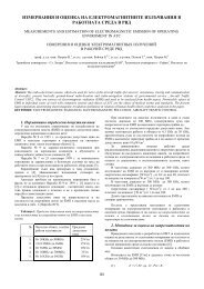
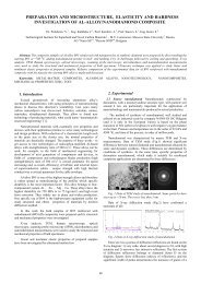
Fig. 3 The influence <strong>of</strong> changes in the selected parameters <strong>of</strong> the<br />
generator - the excitation winding resistance <strong>and</strong> RPM - on the<br />
behaviour <strong>of</strong> the <strong>short</strong>-<strong>circuit</strong> current <strong>of</strong> the DC generator<br />
18<br />
The resulting simulated behaviour <strong>of</strong> the <strong>short</strong>-<strong>circuit</strong> current<br />
corresponds to the theoretical assumptions (Fig. 2). The <strong>short</strong><strong>circuit</strong><br />
current <strong>char<strong>ac</strong>teristics</strong> begins in zero, then rapidly re<strong>ac</strong>hes<br />
the maximum value <strong>of</strong> the <strong>short</strong>-<strong>circuit</strong> current at 790 A, in a period<br />
<strong>of</strong> 0,002s. The influences <strong>of</strong> the change in the selected parameters<br />
<strong>of</strong> the generator - the excitation winding resistance <strong>and</strong> the RPM -<br />
exerted on the behaviour <strong>of</strong> the <strong>short</strong>-<strong>circuit</strong> current is illustrated in<br />
Fig.3. Changing the resistance in the excitation <strong>circuit</strong> within the<br />
range <strong>of</strong> 3,5 Ω to 4,5 Ω, changes the maximum value <strong>of</strong> <strong>short</strong><strong>circuit</strong><br />
current. When R b value increases, the maximum value <strong>of</strong> the<br />
<strong>short</strong>-<strong>circuit</strong> current decreases. The increase in the RPM value rises<br />
the maximum value <strong>of</strong> the <strong>short</strong>-<strong>circuit</strong> current.<br />
3. Short-<strong>circuit</strong> mode <strong>of</strong> the AC generator<br />
Similar appro<strong>ac</strong>h can be adopted also at identifying the AC<br />
generator <strong>and</strong> its subsequent analysis <strong>of</strong> its <strong>char<strong>ac</strong>teristics</strong> when in<br />
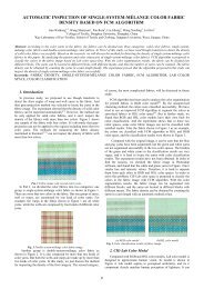
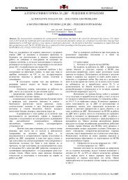
<strong>short</strong>-<strong>circuit</strong> mode. The <strong>short</strong>-<strong>circuit</strong> current in the stator winding is<br />
made up <strong>of</strong> two components: the alternative ia <strong>and</strong> the direct current<br />
id [2]. The resulting time behaviour <strong>of</strong> the <strong>short</strong>-<strong>circuit</strong> current is<br />
illustrated in Fig. 4 <strong>and</strong> the simulated <strong>char<strong>ac</strong>teristics</strong> <strong>of</strong> the<br />
individual components for the <strong>airborne</strong> generator GT-40 PČ6 are in<br />
Fig. 5.<br />
Fig. 4 Behaviour <strong>of</strong> the AC-generator phasing <strong>short</strong>-<strong>circuit</strong> current<br />
4. Conclusion<br />
Time behaviours <strong>of</strong> individual quantities can be monitored when<br />
changing the given input parameters. Simulated behaviours enable<br />
description <strong>of</strong> the basic attributes <strong>of</strong> the generator <strong>and</strong> their changes<br />
when introducing corresponding changes to input parameters.<br />
The models designed are adjusted to the te<strong>ac</strong>hing requirements <strong>of</strong><br />
the given problem. Higher efficiency in applying the results <strong>of</strong><br />
simulation experiments in te<strong>ac</strong>hing, calls for their finalization in<br />
terms <strong>of</strong> did<strong>ac</strong>tics, with the aim to establish an inter<strong>ac</strong>tive<br />
environment enabling optimum presentation <strong>of</strong> the aquired data<br />
<strong>ac</strong>quired as in view <strong>of</strong> the requirements <strong>of</strong> the given subject.