Industrial Type Turbine Flowmeter - Flow-Teknikk
Industrial Type Turbine Flowmeter - Flow-Teknikk
Industrial Type Turbine Flowmeter - Flow-Teknikk

You also want an ePaper? Increase the reach of your titles
YUMPU automatically turns print PDFs into web optimized ePapers that Google loves.
NT Introduction<br />
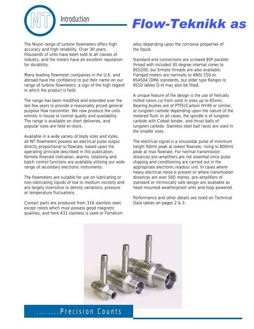
The Nixon range of turbine flowmeters offers high<br />
accuracy and high reliability. Over 30 years,<br />
thousands of units have been sold to all classes of<br />
industry, and the meters have an excellent reputation<br />
for durability.<br />
Many leading flowmeter companies in the U.K. and<br />
abroad have the confidence to put their name on our<br />
range of turbine flowmeters, a sign of the high regard<br />
in which the product is held.<br />
The range has been modified and extended over the<br />
last few years to provide a reasonably priced general<br />
purpose flow transmitter. We now produce the units<br />
entirely in house to control quality and availability.<br />
The range is available on short deliveries, and<br />
popular sizes are held ex-stock.<br />
Available in a wide variety of body sizes and styles,<br />
all NT flowmeters possess an electrical pulse output<br />
directly proportional to flowrate, based upon the<br />
operating principle described in this publication.<br />
Remote flowrate indication, alarms, totalising and<br />
batch control functions are available utilising our wide<br />
range of secondary electronic instruments.<br />
The flowmeters are suitable for use on lubricating or<br />
non-lubricating liquids of low to medium viscosity and<br />
are largely insensitive to density variations, pressure<br />
or temperature fluctuations.<br />
Contact parts are produced from 316 stainless steel,<br />
except rotors which must possess good magnetic<br />
qualities, and here 431 stainless is used or Ferralium<br />
........Precision Counts<br />
<strong>Flow</strong>-<strong>Teknikk</strong> as<br />
alloy depending upon the corrosive properties of<br />
the liquid.<br />
Standard end connections are screwed BSP parallel<br />
thread with included 30 degree internal cones to<br />
BS5200, but Ermeto threads are also available.<br />
Flanged meters are normally to ANSI 150 or<br />
BS4504 (DIN) standards, but older type flanges to<br />
BS10 tables D-H may also be fitted.<br />
A unique feature of the design is the use of helically<br />
milled rotors cut from solid in sizes up to 65mm.<br />
Bearing bushes are of PTFE/Carbon HY49 or similar,<br />
or tungsten carbide depending upon the nature of the<br />
metered fluid. In all cases, the spindle is of tungsten<br />
carbide with Cobalt binder, and thrust balls of<br />
tungsten carbide. Stainless steel ball races are used in<br />
the smaller sizes.<br />
The electrical signal is a sinusoidal pulse of minimum<br />
height 50mV peak at lowest flowrate, rising to 800mV<br />
peak at max flowrate. For normal transmission<br />
distances pre-amplifiers are not essential since pulse<br />
shaping and conditioning are carried out in the<br />
appropriate electronic readout unit. In cases where<br />
heavy electrical noise is present or where transmission<br />
distances are over 500 metres, pre-amplifiers of<br />
standard or intrinsically safe design are available as<br />
head mounted weatherproof units and loop powered.<br />
Performance and other details are listed on Technical<br />
Data tables on pages 2 & 3.
NT<br />
• Linear Accuracy<br />
• Repeatability<br />
• Response Time<br />
• Output Signal<br />
• Operating Pressure<br />
• Pressure Drop<br />
• <strong>Flow</strong> Range<br />
• Temperature<br />
• Transmission Distance<br />
• Mounting Altitude<br />
• Maximum Pressure<br />
Sizing table<br />
<strong>Type</strong> Number<br />
Technical Data<br />
NT<br />
Operations Principle<br />
A ferritic stainless steel rotor revolves within a nonmagnetic<br />
housing on the outside of which is located a<br />
pick off coil containing a permanent magnet. As the<br />
rotor blades pass the tip of the permanent magnet,<br />
the reluctance of the magnetic circuit is changed, and<br />
a small ac voltage is generated in the coil. The<br />
frequency of the ac voltage is proportional to flowrate,<br />
and the total number of pulses produced represents<br />
total flow passed through the meter.<br />
The flowmeter may be located some considerable<br />
distance from the associated secondary instrument,<br />
and remote flowrate indication, total flow, and remote<br />
batch control are thus possible.<br />
Installation and use<br />
For best results the flowmeter should be installed well<br />
away from heavy current carrying cables and with<br />
control valves etc. located downstream of the meter.<br />
A length of straight pipe of bore equal to the meter<br />
inlet should be provided, preferably 10 diameters in<br />
length, and if possible containing flow straightening<br />
vanes at the inlet end. <strong>Turbine</strong> meters are sensitive to<br />
swirl present upstream may cause a change in meter<br />
factor.<br />
Strainers should be provided to minimise the risk of<br />
damage due to small solids in suspension. Meters<br />
may be installed in any attitude, but the flow direction<br />
and mounting attitude should be advised at the order<br />
stage if other than horizontal.<br />
Varying densities have no appreciable effect on the<br />
accuracy of axial flow turbine meters so far as<br />
volumetric flow is concerned. If readout is required in<br />
mass flow terms, we can supply density or<br />
temperature compensation equipment to<br />
automatically correct for density variation. All turbine<br />
meters are to some extent sensitive to viscosity<br />
changes and any likely viscosity variation should be<br />
advised at the order stage.<br />
Servicing may be carried out by our service engineers<br />
in the field, but meters should be returned to our<br />
factory wherever possible for repair. Bearing<br />
replacement can be effected on site by a skilled fitter,<br />
and instructions will be provided on request.<br />
........Precision Counts<br />
When requesting service visits or spares the full serial<br />
number should be stated, which immediately gives us<br />
access to the original order files for the installation.<br />
Dimensions<br />
Allow an extra 50 mm height on dimension 'D' for<br />
pick off coil connector.<br />
A B C D<br />
NT3 51 110 25 82<br />
NT5 64 110 25 82<br />
NT7 64 110 25 82<br />
NT11 85 110 38 84<br />
NT13 85 110 38 86<br />
NT19 114 150 51 89<br />
NT24 114 150 51 91<br />
NT32 135 174 64 95<br />
NT38 150 174 64 98<br />
NT48 180 210 76 103<br />
NT65 - 258 100 112<br />
NT80 - 316 100 119<br />
NT100 - 386 167 130<br />
NT150 - 410 167 155
NT<br />
Calibration method<br />
Water is pumped from storage through the test meter,<br />
through a manual control valve into a collecting tank<br />
mounted upon a standard weighbridge, the vessel<br />
having a drain valve for return to storage.<br />
At the commencement of a calibration, water is<br />
circulated through the system and allowed to drain<br />
whilst the operator regulates the control valve to set<br />
up the approximate desired flowrate. Next, a small<br />
weight, equal to about 10% of tank capacity is<br />
attached to the weighbridge arm, which when the arm<br />
is displaced is arranged by means of microswitches or<br />
an optical system, to switch on a high resolution pulse<br />
counter and a microsecond timer.<br />
The drain valve is closed, and when the level reaches<br />
the preset value, the balance arm starts the<br />
counting procedure.<br />
The operator now re-sets the balance arm, and<br />
attaches weights equal to the desired calibration<br />
volume whilst the collecting tank is filling.<br />
When the second level is reached, the balance arm<br />
again deflects and closes the gating circuit of the<br />
counters.<br />
Thus for one given flowrate, we can calculate pulses<br />
per unit of volume, and also the exact flowrate at<br />
which the calibration took place. This procedure is<br />
<strong>Flow</strong>-<strong>Teknikk</strong> as<br />
Olav Brunborgsv 27, Postboks 244, 1377 BILLINGSTAD<br />
Tlf.: 66 77 54 00 Fax: 66 77 54 01 E-post: mail@flow.no www.flow.no<br />
then repeated at ten points over the operating range<br />
of the meter. Readings of pressure loss and output<br />
voltage are taken and the a.c. waveform is examined<br />
on an oscilloscope to detect any abnormalities in the<br />
rotor blades etc.<br />
A full 10 point calibration certificate is supplied with<br />
every flowmeter.<br />
........Precision Counts